
Arduino Nano 33 IoT - IR Slotted Optical Speed Sensor
This tutorial instructs you how to use Arduino Nano 33 IoT to read the pulses from an IR slotted optical speed sensor, so the board can count passing objects and tell how fast a motor spins. In detail, we will learn:
- How to power the IR slotted optical speed sensor safely from a 3.3V board like the Arduino Nano 33 IoT
- How to connect Arduino Nano 33 IoT to the sensor with only three wires
- How to program Arduino Nano 33 IoT to notice each object that enters the slot and keep a running count
- How to program Arduino Nano 33 IoT to turn the pulses of an encoder disc into revolutions per minute (RPM)
We suggest:
- Utilizing a rotary encoder when a person turns a knob by hand and your code has to know clockwise from anticlockwise.
- Utilizing an IR obstacle avoidance sensor when the thing you want to sense is several centimeters away and cannot fit inside a narrow gap.
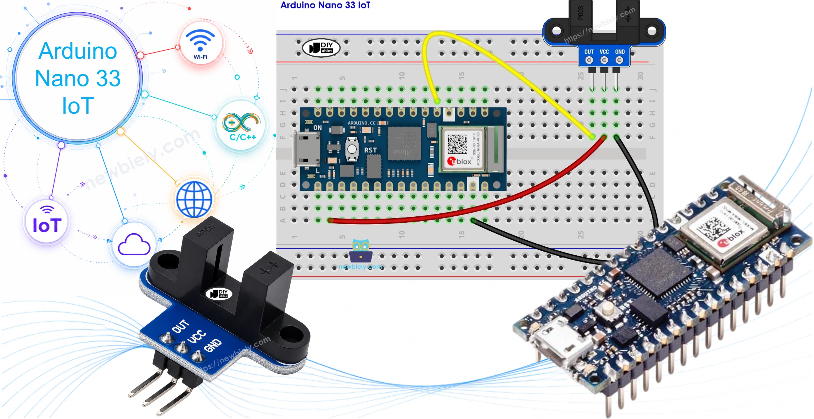
Hardware Preparation
Or you can buy the following kits:
| 1 | × | DIYables Sensor Kit (18 sensors/displays) |
Additionally, some of these links are for products from our own brand, DIYables .
Overview of IR Slotted Optical Speed Sensor
This module is a tiny "beam break" switch with no moving parts. Its body has the shape of the letter U. An object that slips into the opening of the U cuts an invisible infrared beam, and the module reports that event on one digital wire. You may also see it sold as an opto interrupter, a photo interrupter, or a U-shaped IR sensor.
| IR Slotted Optical Speed Sensor | |
|---|---|
| Sensor type | Slot-type photoelectric (IR LED + NPN phototransistor) |
| Slot width | 5.9 mm |
| Operating voltage | 3.3V to 5V DC |
| Output | Digital (TTL), LOW when blocked, HIGH when clear |
| Signal conditioning | Built-in Schmitt trigger |
| Mounting | M3 screw holes at both ends |
| Pins | 3 (VCC, GND, OUT) |
Thanks to the wide 3.3V to 5V supply range, this sensor runs happily on the 3.3V rail of the Arduino Nano 33 IoT. The two M3 holes let you screw it to a robot chassis or a motor bracket, so it stays in line with the moving part.
The IR Slotted Optical Speed Sensor Pinout
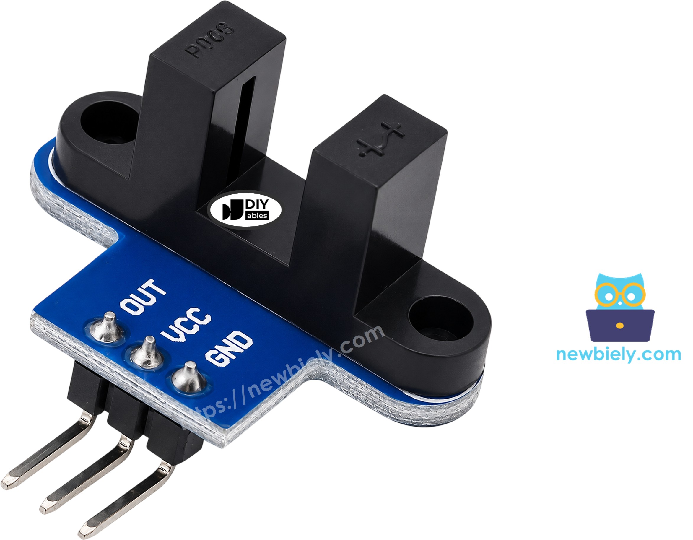
There are three pins on the board edge:
- VCC pin: must be connected to the 3.3V pin of Arduino Nano 33 IoT (not to a 5V source)
- GND pin: must be connected to a GND pin of Arduino Nano 33 IoT (0V)
- OUT pin: carries the HIGH/LOW slot signal; it must be connected to a digital input of Arduino Nano 33 IoT (D2 here)
※ NOTE THAT:
The arrangement of pins on a module may differ from one manufacturer to another, and the DIYables batches do not always use the same order either. It is essential to always refer to the labels printed on the module when using it. Take a close look!
Light Beam Logic: When Is OUT HIGH or LOW?

An infrared LED sits in one leg of the U. An NPN phototransistor sits in the other leg, straight across from it. Between them is the 5.9 mm slot. The LED is always on, so the result depends only on the slot:
| Slot condition | What the phototransistor sees | OUT pin |
|---|---|---|
| Empty | Infrared light | HIGH |
| Opaque object inside (card, disc tooth) | Darkness | LOW |
A Schmitt trigger on the module snaps the signal to a firm 0 or 1, even when an edge moves in slowly. As a result, the Arduino Nano 33 IoT sketch needs no debounce delay at all.
A couple of real-world remarks:
- A clear plastic strip can fool the sensor, because infrared light goes through it. Use something you cannot see through, like card or metal.
- Not every maker uses the same logic. Some third-party modules give LOW with an empty slot. With such a module, swap LOW and HIGH in the counting sketch. The RPM sketch counts one edge per slot, so it stays correct either way.
Wiring Diagram
Connect the sensor to the Arduino Nano 33 IoT as in the picture: VCC to 3.3V, GND to GND, and OUT to D2.
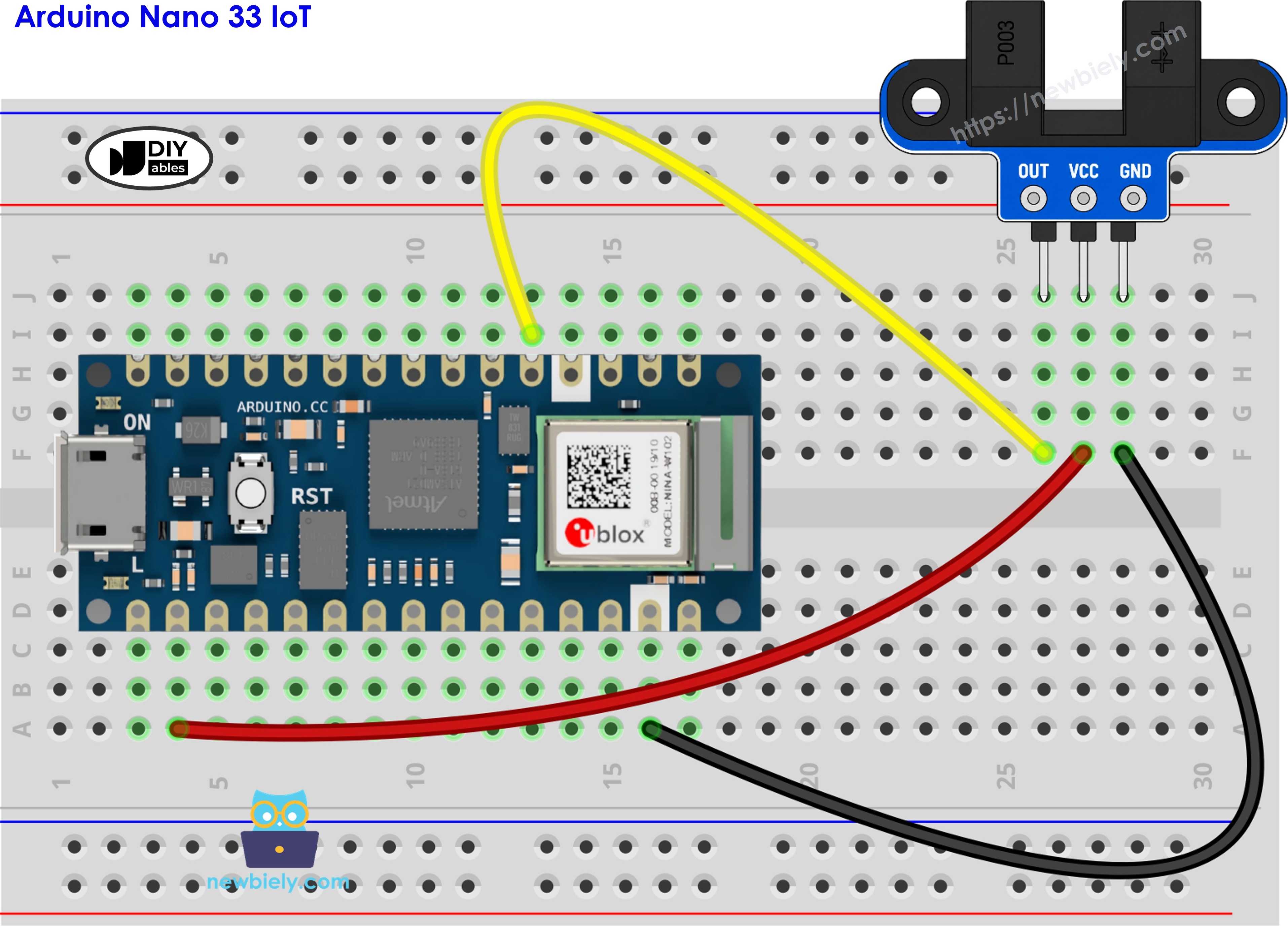
This image is created using Fritzing. Click to enlarge image
Why 3.3V and Not 5V?
The Arduino Nano 33 IoT has the same small Nano shape as the classic Arduino Nano, and it fits the same breadboard spot. Inside, however, it is a 3.3V board, and its input pins are made for 3.3V signals only.
The OUT pin of the sensor rises as high as the voltage on its VCC pin. So the supply you pick decides the signal level:
- VCC from 3.3V: OUT moves between 0V and 3.3V. This is safe for pin D2.
- VCC from 5V: OUT can reach 5V. This is more than a Nano 33 IoT input should ever see.
In short, keep the red wire on the 3.3V pin. Do not copy the 5V wiring from a classic Nano project.
How To Program For IR Slotted Optical Speed Sensor
No extra library is needed. Everything comes from the standard Arduino functions.
Step A: Detecting the Object
- The first step is to give the input pin a name. D2 is the pin wired to OUT:
- Next, that pin is made an input in setup(). The module drives the line itself, so no pull-up is used:
- Then, loop() reads the pin. The value LOW means the beam is cut:
- Finally, the new reading is compared with lastState. A message is printed only on a change, so an object that rests in the slot is still counted once.
Step B: Counting Pulses in the Background
- The first step is a counter marked volatile. The keyword warns the compiler that an interrupt may change it at any time:
- After that comes the interrupt routine. Its only job is to add one:
- In setup(), the routine is tied to D2. With FALLING, it runs at the HIGH-to-LOW edge, which is the exact moment a disc tooth enters the slot:
- Once a second, the sketch takes the count and clears it. Interrupts are paused for these two lines, so a pulse cannot slip in between the copy and the reset and get lost:
- The last line converts pulses per second into RPM:
Arduino Nano 33 IoT Code for Object Detection and Counting
This first sketch watches pin D2 all the time. Every new object in the slot adds one to the count, and the Serial Monitor also tells you when the slot becomes empty again.
Detailed Instructions
- If this is your first project with this board, read Getting Started with Arduino Nano 33 IoT first.
- Wire the components as shown in the diagram. Double-check that VCC goes to 3.3V.
- Connect the Arduino Nano 33 IoT board to your computer using a USB cable.
- Open Arduino IDE on your computer.
- Pick Arduino Nano 33 IoT as the board, then pick its COM port. If the board is missing from the list, install the Arduino SAMD Boards package in the Boards Manager.
- Put the sketch above into the editor.
- Hit Upload to send it to the board.
- Start the Serial Monitor with the speed set to 9600 baud.
- Push a strip of card into the slot and pull it out. Repeat it three times.
- Read the lines that appear on the Serial Monitor.
Does the count go up while the slot is empty? That means your module has inverted output. Exchange LOW and HIGH in the sketch, then upload it again.
Arduino Nano 33 IoT Code for Motor Speed (RPM) Measurement
Fitting the Encoder Disc
To read speed, press a slotted encoder disc onto the motor shaft or the wheel hub. Then place the sensor so the rim of the disc runs through the middle of the U. Each tooth darkens the phototransistor for an instant, and each hole lights it up again. One slot on the disc therefore gives one pulse on D2.
The RPM sketch works like this:
- It counts the falling edges on D2 for one second.
- It multiplies that number by 60 to get pulses per minute.
- It divides by SLOTS_PER_TURN (20 by default, the usual disc for TT gear motors) to get turns per minute.
Why the Sketch Uses an Interrupt
A spinning disc can send pulses faster than loop() can check the pin, especially while the board is busy printing text. An interrupt solves this. The moment D2 falls, the Arduino Nano 33 IoT stops for a tiny moment, runs countPulse(), and goes back to its work. No tooth is skipped.
Detailed Instructions
- Leave the sensor wired exactly as before: 3.3V, GND, and OUT on D2.
- Fix the encoder disc on the shaft. Turn it once by hand and check that no tooth rubs the sensor.
- If your disc does not have 20 slots, count them and write that number into SLOTS_PER_TURN.
- Load the RPM sketch into Arduino IDE and upload it to the Arduino Nano 33 IoT.
- Open the Serial Monitor at 9600 baud.
- Give the disc a spin with your finger, or start the motor. For motor control, follow the Arduino Nano 33 IoT - DC Motor tutorial.
- Watch the pulse count and the speed on the Serial Monitor.
The motor in this test runs close to 300 RPM. Check one line yourself: 101 pulses x 60 = 6060 pulses per minute, and 6060 / 20 = 303 RPM. The zero lines come from the moments before the motor started and after it stopped.
※ NOTE THAT:
Rules for a reliable interrupt sketch:
- Any global variable that the interrupt routine writes must be volatile.
- The routine should be as short as possible. Leave Serial.print() and delay() out of it.
- FALLING gives one count per tooth. CHANGE would count both edges and show twice the real speed.
Additional Knowledge
Three Sensors, Three Jobs
IR slotted optical speed sensor. The target has to pass through the 5.9 mm gap. In return, the sensor sees it at the same spot every time, with a clean edge. This makes it the right part for RPM, pulse counting, and end-stop detection.
IR obstacle avoidance sensor. It looks out into open space and waits for light to bounce back from something in front of it. Use the obstacle sensor for walls, hands, or boxes that will never fit in a slot.
Rotary encoder. It does not look for objects at all. It reports how a knob turns and in which direction, using two signals (CLK and DT) plus a push button. Use the rotary encoder for menus and hand control.
It is evident that the slotted sensor wins when a fast part must be counted exactly, because the beam and the target always meet at one fixed place. It is not the right pick when you need the turning direction.
How Fine Is the RPM Reading?
The sketch counts whole pulses over one second. So the smallest speed change it can show is 60 / SLOTS_PER_TURN RPM:
| Slots on the disc | Pulses per turn | Smallest RPM step |
|---|---|---|
| 10 | 10 | 6 RPM |
| 20 | 20 | 3 RPM |
| 40 | 40 | 1.5 RPM |
A disc with more slots gives finer steps, which helps at low speed. A disc with fewer slots sends fewer interrupts when the motor runs very fast. The common 20-slot disc sits in the middle and suits small gear motors well.
Worked Example: Distance from Wheel Turns
Put the disc on a robot wheel, and the same pulses can tell how far the robot has rolled. Here is a full example with a 20-slot disc and a 60 mm wheel:
- Total pulses counted: 300.
- Wheel turns: 300 / 20 = 15 turns.
- Wheel circumference: π x 60 mm ≈ 188.5 mm.
- Distance: 15 x 188.5 mm ≈ 2828 mm, which is about 2.83 meters.
To build this, keep adding the pulses to a total instead of clearing the counter every second.