
DIYables Web Apps Multiple Web Apps

Overview

This ESP32 S3 Uno multiple web apps tutorial shows you how to run several DIYables web apps at the same time on the ESP32 S3 Uno form board. You build one IoT dashboard that you open in any web browser on your phone or PC. From it you can watch serial messages, move sliders and a joystick, turn a rotator, read a gauge and see a live data table. It is a strong starting point for bigger IoT control panel projects.

In this tutorial, you will:

  1. Install the DIYables ESP32 WebApps library in the Arduino IDE
  2. Upload the MultipleWebApps example to the ESP32 S3 Uno
  3. Open the home page and switch between the web apps
  4. Pick and set the GPIO pins you want to control from the web
  5. Adapt the template for robot, smart home and science projects
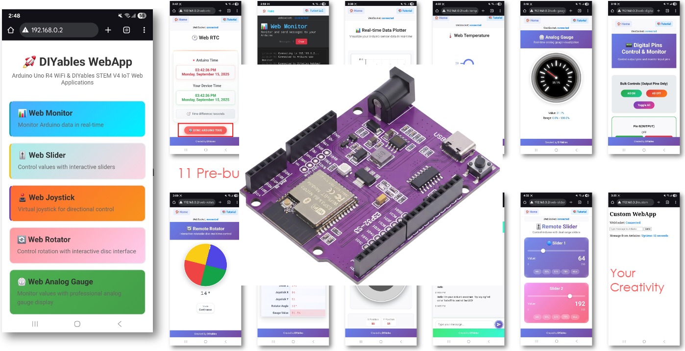
ESP32 S3 Uno multiple web apps

Features

One sketch gives you a full set of web pages. They all share the same state, so a change on one page can show up on another page right away.

Home Page

The home page is the starting point. It holds a link to every web app that the sketch adds to the server.

Monitoring Pages

The Web Monitor works like a Serial Monitor inside your browser. The Web Analog Gauge shows a value on a round dial, and the Web Table lists names and values that update live.

Control Pages

The Web Slider gives you two independent sliders (0 to 255). The Web Joystick sends a 2D position (-100 to 100 on each axis). The Web Rotator gives you a turning disc with an angle from 0 to 360°.

Extra Pages You Can Add

The Chat page and the Web Digital Pins page are not in this sketch, but you can add them with one addApp() line each. The examples further down show how they work together with the other pages.

Under the Hood

All pages talk to the board over WebSocket, so updates happen instantly. The library handles the JSON and the protocol for you, so you only write simple callback functions.

Hardware Preparation

1×ESP32 S3 Uno-form Board
1×USB Cable Type-A to Type-C (for USB-A PC)
1×USB Cable Type-C to Type-C (for USB-C PC)

Or you can buy the following kits:

1×DIYables Sensor Kit (18 sensors/displays)
Disclosure: Some of the links provided in this section are Amazon affiliate links. We may receive a commission for any purchases made through these links at no additional cost to you.
Additionally, some of these links are for products from our own brand, DIYables .

ESP32 S3 Uno Pinout

The image below shows the pinout diagram of the ESP32 S3 Uno form board. Use it to find the Uno header pins (D2, D13, A0…) and their GPIO numbers when you choose pins for the web apps.

ESP32 S3 Uno pinout diagram

Detailed Instructions

The base sketch needs no wiring. You only need the board, a USB cable and a WiFi network with 2.4 GHz.

  1. New to the ESP32 S3 Uno? Follow ESP32 S3 Uno - Getting Started first.
  2. Connect the board to your computer with a USB Type-C cable.
  3. Open Arduino IDE, choose the ESP32S3 Dev Module board and the correct COM port.
  4. Open the Library Manager by clicking the Libraries icon on the left bar of the Arduino IDE.
  5. Search for "DIYables ESP32 WebApps" and find the DIYables ESP32 WebApps Library by DIYables.
  6. Install it by clicking the Install button.
  • Search for DIYables ESP32 WebApps created by DIYables and click the Install button.
∞
Newbiely | Arduino IDE 2.3.8
──
☐
✕
File
Edit
Sketch
Tools
Help
ESP32S3 Dev Module
Library Manager
Type:
All
Topic:
All
DIYables ESP32 WebApps by DIYables
A comprehensive library designed for ESP32 that provides multiple professional web applications including Web Monitor, Chat, Digital Pin Control, Sliders, Joystick, Analog Gauge, Rotator Control, and Temperature Display via WebSocket communication. Features modular architecture for memory efficiency, automatic config handling, and perfect for IoT projects, robotics, sensor monitoring, servo/stepper control, temperature monitoring, and remote ESP32 control. More info
1.0.1
INSTALL
Newbiely.ino
···
1 void setup() {
Output
Serial Monitor
Ln 1, Col 1
ESP32S3 Dev Module on COM15
1
  1. Install the dependencies. The IDE asks to install some other libraries. Click Install All.
  2. Open the example. Go to File Examples DIYables ESP32 WebApps MultipleWebApps, or copy the code below and paste it into the Arduino IDE.
/* * DIYables WebApp Library - Multiple WebApps Example * * This example demonstrates multiple web apps of the DIYables WebApp library: * - Home page with links to multiple web apps * - Web Monitor: Real-time serial monitoring via WebSocket * - Web Slider: Dual slider control * - Web Joystick: Interactive joystick control * - Web Rotator: Interactive rotatable disc control * - Web Analog Gauge: Professional circular gauge for sensor monitoring * - Web Table: Two-column data table with real-time updates * - Web Plotter: See WebPlotter example for real-time data visualization * * Features: * - Simplified callback system - no manual command parsing needed * - Automatic state synchronization and JSON handling * - All protocol details handled by the library * - Template for hardware control * * Hardware: ESP32 S3 Uno form board * * Setup: * 1. Update WiFi credentials below * 2. Upload the sketch to your ESP32 S3 Uno * 3. Open Serial Monitor to see the IP address * 4. Navigate to the IP address in your web browser */ #include <DIYables_ESP32_Platform.h> #include <DIYablesWebApps.h> // WiFi credentials - UPDATE THESE WITH YOUR NETWORK const char WIFI_SSID[] = "YOUR_WIFI_SSID"; const char WIFI_PASSWORD[] = "YOUR_WIFI_PASSWORD"; // Create WebApp server and page instances ESP32ServerFactory factory; DIYablesWebAppServer webAppsServer(factory, 80, 81); DIYablesHomePage homePage; DIYablesWebMonitorPage webMonitorPage; DIYablesWebSliderPage webSliderPage; DIYablesWebJoystickPage webJoystickPage(false, 5); // autoReturn=false, sensitivity=5 DIYablesWebRotatorPage webRotatorPage(ROTATOR_MODE_CONTINUOUS); // Continuous rotation mode (0-360°) DIYablesWebAnalogGaugePage webAnalogGaugePage(0.0, 100.0, "%"); // Range: 0-100%, units: % DIYablesWebTablePage webTablePage; // Variables to track states int currentSlider1 = 64; // Slider 1 value (0-255) int currentSlider2 = 128; // Slider 2 value (0-255) int currentJoystickX = 0; // Current joystick X value (-100 to 100) int currentJoystickY = 0; // Current joystick Y value (-100 to 100) int currentRotatorAngle = 0; // Current rotator angle (0-360°) float currentGaugeValue = 50.0; // Current gauge value (0.0-100.0) void setup() { Serial.begin(9600); delay(1000); // TODO: Initialize your hardware pins here Serial.println("DIYables ESP32 WebApp - Multiple Apps Example"); // Add all web applications to the server webAppsServer.addApp(&homePage); webAppsServer.addApp(&webMonitorPage); webAppsServer.addApp(&webSliderPage); webAppsServer.addApp(&webJoystickPage); webAppsServer.addApp(&webRotatorPage); webAppsServer.addApp(&webAnalogGaugePage); webAppsServer.addApp(&webTablePage); // Add more web apps here (e.g., WebPlotter) // Set 404 Not Found page (optional - for better user experience) webAppsServer.setNotFoundPage(DIYablesNotFoundPage()); // Configure table structure (only attribute names, values will be updated dynamically) webTablePage.addRow("Arduino Status"); webTablePage.addRow("WiFi Connected"); webTablePage.addRow("Uptime"); webTablePage.addRow("Slider 1"); webTablePage.addRow("Slider 2"); webTablePage.addRow("Joystick X"); webTablePage.addRow("Joystick Y"); webTablePage.addRow("Rotator Angle"); webTablePage.addRow("Gauge Value"); // Start the WebApp server if (!webAppsServer.begin(WIFI_SSID, WIFI_PASSWORD)) { while (1) { Serial.println("Failed to start WebApp server!"); delay(1000); } } setupCallbacks(); } void setupCallbacks() { // Web Monitor callback - echo messages back webMonitorPage.onWebMonitorMessage([](const String& message) { Serial.println("Web Monitor: " + message); webMonitorPage.sendToWebMonitor("Arduino received: " + message); }); // Web Slider callback - handle slider values webSliderPage.onSliderValueFromWeb([](int slider1, int slider2) { // Store the received values currentSlider1 = slider1; currentSlider2 = slider2; // Print slider values (0-255) without String concatenation Serial.print("Slider 1: "); Serial.print(slider1); Serial.print(", Slider 2: "); Serial.println(slider2); // Update table with new slider values using String() conversion webTablePage.sendValueUpdate("Slider 1", String(slider1)); webTablePage.sendValueUpdate("Slider 2", String(slider2)); // TODO: Add your control logic here based on slider values // Examples: // - Control PWM: analogWrite(LED_PIN, slider1); // - Control servos: servo.write(map(slider1, 0, 255, 0, 180)); // - Control motor speed: analogWrite(MOTOR_PIN, slider2); // Update gauge based on slider1 value (map 0-255 to 0-100) currentGaugeValue = map(slider1, 0, 255, 0, 100); webAnalogGaugePage.sendToWebAnalogGauge(currentGaugeValue); char gaugeStr[16]; snprintf(gaugeStr, sizeof(gaugeStr), "%.1f%%", currentGaugeValue); webTablePage.sendValueUpdate("Gauge Value", String(gaugeStr)); }); // Handle slider value requests webSliderPage.onSliderValueToWeb([]() { webSliderPage.sendToWebSlider(currentSlider1, currentSlider2); }); // Web Joystick callback - handle joystick movement webJoystickPage.onJoystickValueFromWeb([](int x, int y) { // Store the received values currentJoystickX = x; currentJoystickY = y; // Print joystick position values (-100 to +100) Serial.print("Joystick - X: "); Serial.print(x); Serial.print(", Y: "); Serial.println(y); Serial.print(x); Serial.print(", Y: "); Serial.println(y); // Update table with new joystick values webTablePage.sendValueUpdate("Joystick X", String(x)); webTablePage.sendValueUpdate("Joystick Y", String(y)); // TODO: Add your control logic here based on joystick position // Examples: // - Control motors: if (x > 50) { /* move right */ } // - Control servos: servo.write(map(y, -100, 100, 0, 180)); // - Control LEDs: analogWrite(LED_PIN, map(abs(x), 0, 100, 0, 255)); }); // Handle joystick values requests (when web page loads/reconnects) webJoystickPage.onJoystickValueToWeb([]() { webJoystickPage.sendToWebJoystick(currentJoystickX, currentJoystickY); }); // Web Rotator callback - handle rotation angle changes webRotatorPage.onRotatorAngleFromWeb([](float angle) { // Store the received angle currentRotatorAngle = (int)angle; // Print rotator angle (0-360°) Serial.println("Rotator angle: " + String(angle) + "°"); // Update table with new rotator angle webTablePage.sendValueUpdate("Rotator Angle", String(angle, 0) + "°"); // TODO: Add your control logic here based on rotator angle // Examples: // - Control servo: servo.write(map(angle, 0, 360, 0, 180)); // - Control stepper motor: stepper.moveTo(angle); // - Control directional LED strip: setLEDDirection(angle); }); // Handle analog gauge value requests (when web page loads/reconnects) webAnalogGaugePage.onGaugeValueRequest([]() { webAnalogGaugePage.sendToWebAnalogGauge(currentGaugeValue); }); // Handle table data requests (when web page loads/reconnects) webTablePage.onTableValueRequest([]() { // Send initial values to the table webTablePage.sendValueUpdate("Arduino Status", "Running"); webTablePage.sendValueUpdate("WiFi Connected", "Yes"); webTablePage.sendValueUpdate("Uptime", "0 seconds"); webTablePage.sendValueUpdate("Slider 1", String(currentSlider1)); webTablePage.sendValueUpdate("Slider 2", String(currentSlider2)); webTablePage.sendValueUpdate("Joystick X", String(currentJoystickX)); webTablePage.sendValueUpdate("Joystick Y", String(currentJoystickY)); webTablePage.sendValueUpdate("Rotator Angle", String(currentRotatorAngle) + "°"); webTablePage.sendValueUpdate("Gauge Value", String(currentGaugeValue, 1) + "%"); }); } void loop() { // Handle WebApp server communications webAppsServer.loop(); // Update table with current uptime every 5 seconds static unsigned long lastUptimeUpdate = 0; if (millis() - lastUptimeUpdate > 5000) { lastUptimeUpdate = millis(); unsigned long uptimeSeconds = millis() / 1000; String uptimeStr = String(uptimeSeconds) + " seconds"; if (uptimeSeconds >= 60) { uptimeStr = String(uptimeSeconds / 60) + "m " + String(uptimeSeconds % 60) + "s"; } webTablePage.sendValueUpdate("Uptime", uptimeStr); } // Simulate sensor data updates every 3 seconds static unsigned long lastSensorUpdate = 0; if (millis() - lastSensorUpdate > 3000) { lastSensorUpdate = millis(); // Simulate a sensor reading that varies over time float sensorValue = 50.0 + 30.0 * sin(millis() / 10000.0); // Oscillates between 20-80 currentGaugeValue = sensorValue; // Update gauge and table webAnalogGaugePage.sendToWebAnalogGauge(currentGaugeValue); webTablePage.sendValueUpdate("Gauge Value", String(currentGaugeValue, 1) + "%"); } // TODO: Add your main application code here delay(10); }
  1. Set your WiFi name and password in these two lines:
const char WIFI_SSID[] = "YOUR_WIFI_SSID"; const char WIFI_PASSWORD[] = "YOUR_WIFI_PASSWORD";
  1. Upload the code. Click the Upload button to send the sketch to the ESP32 S3 Uno.
  2. Open the Serial Monitor and set it to 9600 baud. You should see something like this:
∞
Newbiely | Arduino IDE 2.3.8
──
☐
✕
File
Edit
Sketch
Tools
Help
ESP32S3 Dev Module
Newbiely.ino
···
8 Serial.println("Hello World!");
Output
Serial Monitor
Message (Enter to send message to 'ESP32S3 Dev Module' on 'COM15')
New Line
9600 baud
DIYables ESP32 WebApp - Multiple Apps Example INFO: Added app / INFO: Added app /web-monitor INFO: Added app /web-slider INFO: Added app /web-joystick INFO: Added app /web-rotator INFO: Added app /web-gauge INFO: Added app /web-table DIYables WebApp Library Platform: ESP32 Network connected! IP address: 192.168.0.2 HTTP server started on port 80 Configuring WebSocket server callbacks... WebSocket server started on port 81 WebSocket URL: ws://192.168.0.2:81 WebSocket server started on port 81 ========================================== DIYables WebApp Ready! ========================================== 📱 Web Interface: http://192.168.0.2 🔗 WebSocket: ws://192.168.0.2:81 📋 Available Applications: 🏠 Home Page: http://192.168.0.2/ 📊 Web Monitor: http://192.168.0.2/web-monitor 🎚️ Web Slider: http://192.168.0.2/web-slider 🕹️ Web Joystick: http://192.168.0.2/web-joystick 🔄 Web Rotator: http://192.168.0.2/web-rotator ⏲️ Web Analog Gauge: http://192.168.0.2/web-gauge 📊 Web Table: http://192.168.0.2/web-table ==========================================
Ln 11, Col 1
ESP32S3 Dev Module on COM15
2
  1. Nothing printed? Press the RESET button on the ESP32 S3 Uno and watch the Serial Monitor again.
  2. Open the dashboard. Write down the IP address and type it into the address bar of a web browser on your phone or PC, for example http://192.168.0.2. The phone or PC must be on the same WiFi network.
  3. Check the home page. It shows a link to every web app:
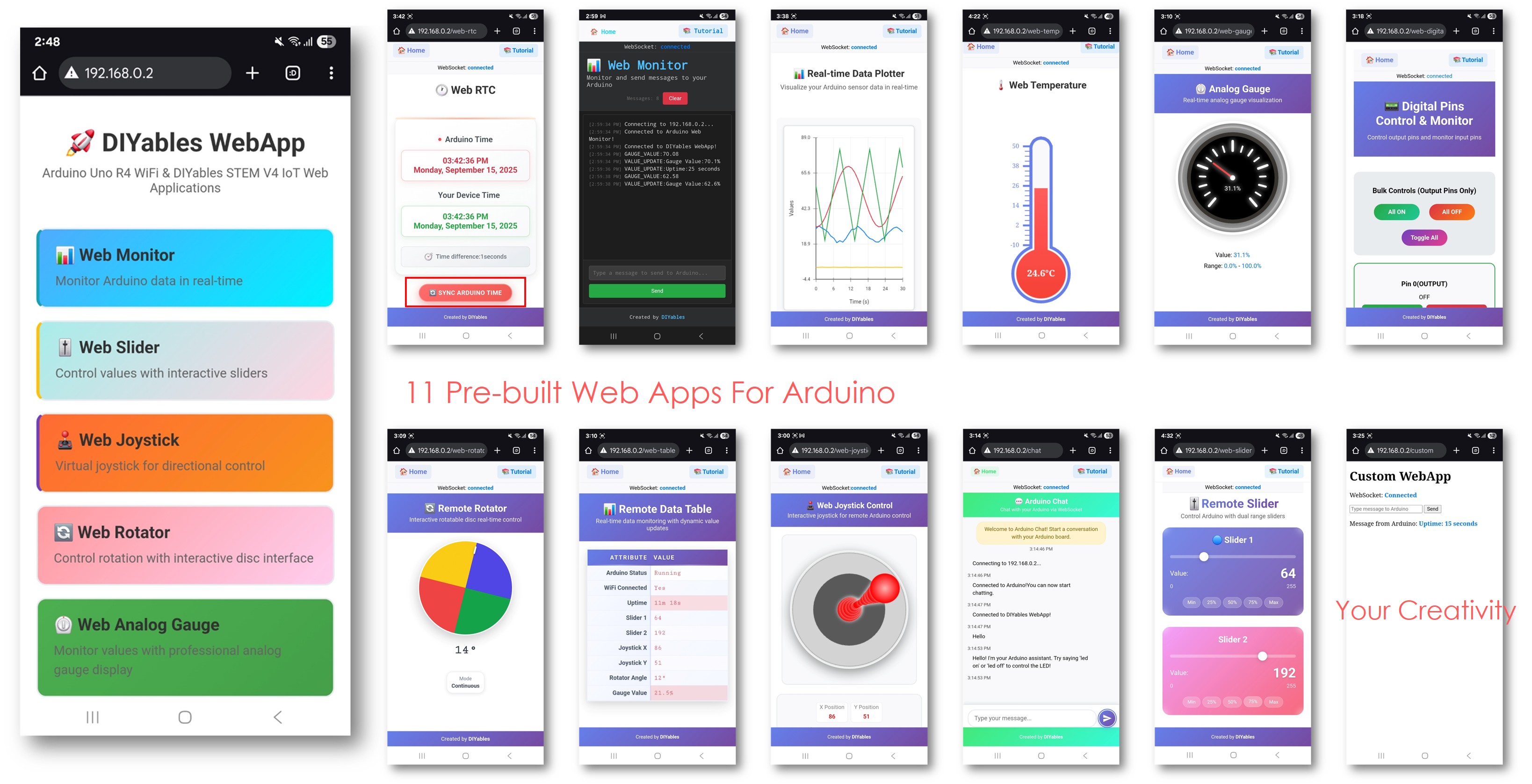
ESP32 S3 Uno DIYables WebApp Home page with Multiple Web Apps
  1. Try each app. Click a link to open that app, or type the path after the IP address, such as http://192.168.0.2/web-monitor or http://192.168.0.2/web-slider. Move the sliders, drag the joystick and turn the rotator, then look at the Web Table to see the values change.
  2. Tip: Bookmark the home page on your phone. If the IP address changes after a router restart, check the Serial Monitor again for the new one.

Web Interface Navigation

Every web app has its own path on the board's web server. Knowing these paths lets you jump straight to the page you need, or share one page with someone else.

Home Page Dashboard

The home page at / is your control center. It lists only the apps that the sketch added with addApp(), so the list changes when you add or remove apps.

Application URLs

These are the paths used by the MultipleWebApps sketch. The Chat and Digital Pins paths work only after you add those apps to the server.

http://[ESP32_S3_UNO_IP]/ # Home page http://[ESP32_S3_UNO_IP]/web-monitor # Serial monitor interface http://[ESP32_S3_UNO_IP]/web-slider # Dual slider control http://[ESP32_S3_UNO_IP]/web-joystick # Joystick control http://[ESP32_S3_UNO_IP]/web-rotator # Rotator disc control http://[ESP32_S3_UNO_IP]/web-gauge # Analog gauge http://[ESP32_S3_UNO_IP]/web-table # Data table http://[ESP32_S3_UNO_IP]/chat # Chat interface (if added) http://[ESP32_S3_UNO_IP]/digital-pins # Pin control (if added)

To learn each app on its own, see ESP32 S3 Uno - Web Monitor, ESP32 S3 Uno - Web Slider, ESP32 S3 Uno - Web Joystick, ESP32 S3 Uno - Chat and ESP32 S3 Uno - Web Digital Pins.

Creative Customization - Unleash Your Innovation

The example is a template. You keep the parts you need, remove the rest, and connect the callbacks to your own hardware. The snippets below show the main settings you will change.

Digital Pin Configuration

When you add the Web Digital Pins app, you tell it which pins to show and whether each one is an output or an input. The library only accepts numbers 0 to 13, so on the ESP32 S3 Uno you pass the Uno header label (2 means D2). In your own pinMode(), digitalWrite() and digitalRead() code, turn that label into the real GPIO, for example with the UNO_TO_GPIO table from the Web Digital Pins tutorial.

Output Pins (Controllable via Web)

webDigitalPinsPage.enablePin(2, WEB_PIN_OUTPUT); // D2 (GPIO18) - general purpose output webDigitalPinsPage.enablePin(3, WEB_PIN_OUTPUT); // D3 (GPIO17) - general purpose output webDigitalPinsPage.enablePin(4, WEB_PIN_OUTPUT); // D4 (GPIO19) - general purpose output webDigitalPinsPage.enablePin(13, WEB_PIN_OUTPUT); // D13 (GPIO12) - external LED

The ESP32 S3 Uno has no built-in LED on D13. Connect an external LED with a 220 ohm resistor to D13 (GPIO12) if you want a light to switch from the web page.

Input Pins (Monitored via Web)

webDigitalPinsPage.enablePin(8, WEB_PIN_INPUT); // D8 (GPIO21) - sensor input webDigitalPinsPage.enablePin(9, WEB_PIN_INPUT); // D9 (GPIO46) - switch input

WARNING

D9 (GPIO46) is a boot strapping pin on the ESP32 S3 Uno. The chip reads it at power-up to pick the boot mode. If a switch or sensor pulls it to the wrong level during reset, the board may not boot or accept new code. Release the switch while you power up or upload, or move this input to a free pin such as D8 or D12.

All ESP32 S3 Uno pins use 3.3V logic and are NOT 5V tolerant. Do not connect a 5V sensor output straight to an input pin.

Joystick Configuration

You can change how the joystick behaves when you create it. The first value turns auto-return on or off, and the second value sets how far it must move before it sends a new update.

// Create joystick with custom settings // autoReturn=false: Joystick stays at last position when released // sensitivity=5: Only send updates when movement > 5% DIYablesWebJoystickPage webJoystickPage(false, 5);

State Variables

Global variables keep the current value of each control. Every page reads from them when it loads, so all pages stay in sync. The pin state array is indexed by the Uno label (D0 to D13), the same numbers the Web Digital Pins page uses.

int pinStates[14] = { LOW }; // Track pin states (Uno labels D0-D13) int currentSlider1 = 64; // Slider 1 value (0-255) - 25% int currentSlider2 = 128; // Slider 2 value (0-255) - 50% int currentJoystickX = 0; // Joystick X value (-100 to 100) int currentJoystickY = 0; // Joystick Y value (-100 to 100)

Built-in Chat Commands

If you add the Chat page, the chat example answers a few ready-made commands. They are a good model for your own text commands.

Basic Commands

Command What the ESP32 S3 Uno replies
hello A friendly greeting
time How many seconds the board has been running
status The board status and the LED state
help The list of commands

Control Commands

Type led on to switch the LED on, and led off to switch it off. On the ESP32 S3 Uno this is the external LED on D13 (GPIO12), because the board has no built-in LED there.

Example Chat Session

User: hello ESP32 S3 Uno: Hello! I'm your Arduino. How can I help you? User: led on ESP32 S3 Uno: Built-in LED is now ON! User: time ESP32 S3 Uno: I've been running for 1245 seconds. User: status ESP32 S3 Uno: Status: Running smoothly! LED is ON

Programming Integration Examples

The real power of this example shows when you link several pages to one piece of hardware. The three examples below are partial sketches. Add them to the MultipleWebApps sketch and change the pins to fit your wiring.

Complete Robot Control System

This example drives a small robot. The joystick steers with tank-style drive, slider 1 sets the top speed, slider 2 tilts a camera, the digital pins switch lights and a horn, and the chat page takes stop commands. Note that Servo.h becomes ESP32Servo.h on the ESP32 S3 Uno (install the "ESP32Servo" library by Kevin Harrington).

#include <ESP32Servo.h> // Hardware definitions (ESP32 S3 Uno GPIO numbers) const int MOTOR_LEFT_PWM = 46; // D9 (GPIO46) const int MOTOR_RIGHT_PWM = 10; // D10 (GPIO10) const int SERVO_PAN = 11; // D11 (GPIO11) const int SERVO_TILT = 13; // D12 (GPIO13) const int LED_STRIP_PIN = 3; // D6 (GPIO3) Servo panServo, tiltServo; void setup() { // Initialize hardware panServo.attach(SERVO_PAN); tiltServo.attach(SERVO_TILT); pinMode(MOTOR_LEFT_PWM, OUTPUT); pinMode(MOTOR_RIGHT_PWM, OUTPUT); // ... WebApp setup code ... setupRobotCallbacks(); } void setupRobotCallbacks() { // Use joystick for robot movement webJoystickPage.onJoystickValueFromWeb([](int x, int y) { // Convert joystick to tank drive int leftSpeed = y + (x / 2); int rightSpeed = y - (x / 2); leftSpeed = constrain(leftSpeed, -100, 100); rightSpeed = constrain(rightSpeed, -100, 100); // Apply speed limits from sliders leftSpeed = map(leftSpeed, -100, 100, -currentSlider1, currentSlider1); rightSpeed = map(rightSpeed, -100, 100, -currentSlider1, currentSlider1); // Control motors analogWrite(MOTOR_LEFT_PWM, abs(leftSpeed)); analogWrite(MOTOR_RIGHT_PWM, abs(rightSpeed)); Serial.println("Robot - Left: " + String(leftSpeed) + ", Right: " + String(rightSpeed)); }); // Use sliders for camera pan/tilt control webSliderPage.onSliderValueFromWeb([](int slider1, int slider2) { // Slider 1 controls maximum speed, Slider 2 controls camera tilt int panAngle = map(currentJoystickX, -100, 100, 0, 180); int tiltAngle = map(slider2, 0, 255, 0, 180); panServo.write(panAngle); tiltServo.write(tiltAngle); Serial.println("Camera - Pan: " + String(panAngle) + "°, Tilt: " + String(tiltAngle) + "°"); }); // Use digital pins for special functions webDigitalPinsPage.onPinWrite([](int pin, int state) { switch (pin) { case 18: // D2 (GPIO18) - Headlights digitalWrite(pin, state); Serial.println("Headlights " + String(state ? "ON" : "OFF")); break; case 17: // D3 (GPIO17) - Horn/Buzzer if (state) { // Trigger buzzer sequence digitalWrite(pin, HIGH); delay(200); digitalWrite(pin, LOW); } break; case 19: // D4 (GPIO19) - Emergency stop if (state) { analogWrite(MOTOR_LEFT_PWM, 0); analogWrite(MOTOR_RIGHT_PWM, 0); Serial.println("EMERGENCY STOP ACTIVATED"); } break; } }); // Enhanced chat commands for robot control chatPage.onChatMessage([](const String& message) { String msg = message; msg.toLowerCase(); if (msg.indexOf("stop") >= 0) { analogWrite(MOTOR_LEFT_PWM, 0); analogWrite(MOTOR_RIGHT_PWM, 0); chatPage.sendToChat("Robot stopped!"); return; } if (msg.indexOf("center camera") >= 0) { panServo.write(90); tiltServo.write(90); chatPage.sendToChat("Camera centered!"); return; } if (msg.indexOf("speed") >= 0) { String response = "Current max speed: " + String(map(currentSlider1, 0, 255, 0, 100)) + "%"; chatPage.sendToChat(response); return; } // Default response for unknown commands chatPage.sendToChat("Robot commands: stop, center camera, speed"); }); }

WARNING

This robot example uses D9 (GPIO46) for the left motor and D6 (GPIO3) for the LED strip. Both are boot strapping pins on the ESP32 S3 Uno. A motor driver or LED strip that pulls these pins high or low at power-up can stop the board from booting or uploading. If that happens, disconnect them while you upload, or move them to free pins.

Smart Home Control System

Here the digital pins switch the lights in three rooms, the two sliders set fan and air conditioner power with PWM, and the chat page reports the motion and door sensors. Any change also shows up in the chat and the Web Monitor.

// Home automation pin assignments (ESP32 S3 Uno GPIO numbers) const int LIVING_ROOM_LIGHTS = 18; // D2 (GPIO18) const int BEDROOM_LIGHTS = 17; // D3 (GPIO17) const int KITCHEN_LIGHTS = 19; // D4 (GPIO19) const int FAN_CONTROL = 46; // D9 (GPIO46) const int AC_CONTROL = 10; // D10 (GPIO10) const int MOTION_SENSOR = 21; // D8 (GPIO21) const int DOOR_SENSOR = 46; // D9 (GPIO46) void setupHomeAutomation() { // Configure home automation pins pinMode(LIVING_ROOM_LIGHTS, OUTPUT); pinMode(BEDROOM_LIGHTS, OUTPUT); pinMode(KITCHEN_LIGHTS, OUTPUT); pinMode(FAN_CONTROL, OUTPUT); pinMode(AC_CONTROL, OUTPUT); pinMode(MOTION_SENSOR, INPUT); pinMode(DOOR_SENSOR, INPUT_PULLUP); // Digital pins for room lighting control webDigitalPinsPage.onPinWrite([](int pin, int state) { digitalWrite(pin, state); String room; switch (pin) { case 18: room = "Living Room"; break; case 17: room = "Bedroom"; break; case 19: room = "Kitchen"; break; default: room = "Pin " + String(pin); break; } Serial.println(room + " lights " + String(state ? "ON" : "OFF")); // Send notification to chat String message = room + " lights turned " + String(state ? "ON" : "OFF"); chatPage.sendToChat(message); }); // Sliders for fan and AC control webSliderPage.onSliderValueFromWeb([](int slider1, int slider2) { // Slider 1 controls fan speed (0-255) analogWrite(FAN_CONTROL, slider1); // Slider 2 controls AC intensity (0-255) analogWrite(AC_CONTROL, slider2); Serial.println("Fan: " + String(map(slider1, 0, 255, 0, 100)) + "%, " + "AC: " + String(map(slider2, 0, 255, 0, 100)) + "%"); }); // Enhanced chat commands for home control chatPage.onChatMessage([](const String& message) { String msg = message; msg.toLowerCase(); if (msg.indexOf("all lights on") >= 0) { digitalWrite(LIVING_ROOM_LIGHTS, HIGH); digitalWrite(BEDROOM_LIGHTS, HIGH); digitalWrite(KITCHEN_LIGHTS, HIGH); chatPage.sendToChat("All lights turned ON!"); return; } if (msg.indexOf("all lights off") >= 0) { digitalWrite(LIVING_ROOM_LIGHTS, LOW); digitalWrite(BEDROOM_LIGHTS, LOW); digitalWrite(KITCHEN_LIGHTS, LOW); chatPage.sendToChat("All lights turned OFF!"); return; } if (msg.indexOf("temperature") >= 0) { String response = "Fan: " + String(map(currentSlider1, 0, 255, 0, 100)) + "%, " + "AC: " + String(map(currentSlider2, 0, 255, 0, 100)) + "%"; chatPage.sendToChat(response); return; } if (msg.indexOf("security") >= 0) { bool motion = digitalRead(MOTION_SENSOR); bool door = digitalRead(DOOR_SENSOR); String status = "Motion: " + String(motion ? "DETECTED" : "CLEAR") + ", Door: " + String(door ? "CLOSED" : "OPEN"); chatPage.sendToChat(status); return; } // Default home automation help chatPage.sendToChat("Home commands: all lights on/off, temperature, security"); }); } void loop() { webAppsServer.loop(); // Monitor home security sensors static bool lastMotion = false; static bool lastDoor = false; bool currentMotion = digitalRead(MOTION_SENSOR); bool currentDoor = digitalRead(DOOR_SENSOR); // Send alerts for security events if (currentMotion != lastMotion) { if (currentMotion) { chatPage.sendToChat("🚨 MOTION DETECTED!"); webMonitorPage.sendToWebMonitor("Security Alert: Motion detected"); } lastMotion = currentMotion; } if (currentDoor != lastDoor) { String status = currentDoor ? "CLOSED" : "OPENED"; chatPage.sendToChat("🚪 Door " + status); webMonitorPage.sendToWebMonitor("Security: Door " + status); lastDoor = currentDoor; } delay(10); }

※ NOTE THAT:

In this template FAN_CONTROL and DOOR_SENSOR both point to D9 (GPIO46), the same as in the original example. One pin cannot be a PWM output and an input at the same time, so give one of them another free pin before you build the real project. D9 (GPIO46) is also a boot strapping pin.

Educational Science Project

This example runs a small lab experiment. Slider 1 sets the target temperature, slider 2 sets the stirrer speed, the chat page reads the data, and the Web Monitor logs a CSV line when you type log. The sensors are read on A0 (GPIO2) and A1 (GPIO1).

// Science experiment control system (ESP32 S3 Uno GPIO numbers) const int HEATING_ELEMENT = 46; // D9 (GPIO46) const int COOLING_FAN = 10; // D10 (GPIO10) const int STIRRER_MOTOR = 11; // D11 (GPIO11) const int TEMP_SENSOR_PIN = 2; // A0 (GPIO2) const int PH_SENSOR_PIN = 1; // A1 (GPIO1) void setupScienceExperiment() { // set the ADC attenuation to 11 dB (up to ~3.3V input) analogSetAttenuation(ADC_11db); // Sliders for temperature and stirring control webSliderPage.onSliderValueFromWeb([](int slider1, int slider2) { // Slider 1 controls target temperature (mapped to heating/cooling) int targetTemp = map(slider1, 0, 255, 20, 80); // 20-80°C range // Slider 2 controls stirrer speed analogWrite(STIRRER_MOTOR, slider2); // Simple temperature control logic int currentTemp = readTemperature(); if (currentTemp < targetTemp) { analogWrite(HEATING_ELEMENT, 200); // Heat on analogWrite(COOLING_FAN, 0); // Fan off } else if (currentTemp > targetTemp + 2) { analogWrite(HEATING_ELEMENT, 0); // Heat off analogWrite(COOLING_FAN, 255); // Fan on } else { analogWrite(HEATING_ELEMENT, 0); // Both off (maintain) analogWrite(COOLING_FAN, 0); } Serial.println("Target: " + String(targetTemp) + "°C, Current: " + String(currentTemp) + "°C"); }); // Chat interface for experiment control and data chatPage.onChatMessage([](const String& message) { String msg = message; msg.toLowerCase(); if (msg.indexOf("data") >= 0) { int temp = readTemperature(); float ph = readPH(); String data = "Temperature: " + String(temp) + "°C, pH: " + String(ph, 2); chatPage.sendToChat(data); return; } if (msg.indexOf("start") >= 0) { // Begin experiment sequence chatPage.sendToChat("🔬 Experiment started! Monitoring conditions..."); return; } if (msg.indexOf("stop") >= 0) { // Emergency stop analogWrite(HEATING_ELEMENT, 0); analogWrite(COOLING_FAN, 0); analogWrite(STIRRER_MOTOR, 0); chatPage.sendToChat("⚠️ Experiment stopped - all systems OFF"); return; } chatPage.sendToChat("Science commands: data, start, stop"); }); // Monitor for automatic data logging webMonitorPage.onWebMonitorMessage([](const String& message) { if (message == "log") { int temp = readTemperature(); float ph = readPH(); String logEntry = String(millis()) + "," + String(temp) + "," + String(ph, 2); webMonitorPage.sendToWebMonitor(logEntry); } }); } int readTemperature() { // Read temperature sensor (example implementation) int sensorValue = analogRead(TEMP_SENSOR_PIN); return map(sensorValue, 0, 4095, 0, 100); // 12-bit ADC (0-4095) to temperature } float readPH() { // Read pH sensor (example implementation) int sensorValue = analogRead(PH_SENSOR_PIN); return map(sensorValue, 0, 4095, 0, 14) / 10.0; // 12-bit ADC (0-4095) to pH }

The ESP32 S3 Uno ADC is 12-bit, so analogRead() returns 0 to 4095 instead of 0 to 1023. That is why the map() calls use 4095. The analogSetAttenuation(ADC_11db) line matters too: by default the ADC can only measure a small voltage, and 11 dB attenuation lets the analog pins read the full range from 0V up to about 3.3V. Without it, the readings hit 4095 too early and the sensor values look wrong. Call setupScienceExperiment() from setup() so this line runs once at start-up.

Advanced Integration Techniques

As your project grows, two things become important: keeping every page showing the same values, and letting one page change what another page does.

State Synchronization

This function pushes the current values to every page. Call it after a big change, or when a page reconnects. The loop goes through all GPIO numbers, because ESP32 S3 Uno pins are numbered by GPIO, not by Uno header.

void synchronizeAllStates() { // Ensure all interfaces show current state webSliderPage.sendToWebSlider(currentSlider1, currentSlider2); webJoystickPage.sendToWebJoystick(currentJoystickX, currentJoystickY); // Update all pin states for (int pin = 0; pin <= 13; pin++) { if (webDigitalPinsPage.isPinEnabled(pin)) { webDigitalPinsPage.updatePinState(pin, pinStates[pin]); } } Serial.println("All interface states synchronized"); }

Cross-Interface Communication

Here the joystick distance can limit the slider range, and the pin on D2 (GPIO18) works as an "arm" switch that sends a message to the chat page.

void setupCrossInterfaceCommunication() { // Joystick position affects slider maximum values webJoystickPage.onJoystickValueFromWeb([](int x, int y) { // Calculate distance from center float distance = sqrt(x*x + y*y); // Limit slider maximum based on joystick distance if (distance > 50) { // Reduce maximum slider values when joystick is far from center int maxValue = map(distance, 50, 100, 255, 128); // You could implement dynamic slider limiting here } }); // Pin states affect available chat commands webDigitalPinsPage.onPinWrite([](int pin, int state) { if (pin == 18 && state == HIGH) { // D2 (GPIO18) chatPage.sendToChat("📢 System armed - additional commands available"); } else if (pin == 18 && state == LOW) { chatPage.sendToChat("📢 System disarmed - limited commands only"); } }); }

Common Issues and Debugging

Running many pages at once can bring a few special problems. Most of them are easy to fix once you know where to look.

Some pages do not load

Check that every app is added to the server with addApp() in setup(). Open the browser console and look for WebSocket errors. Make sure the board still has enough free memory.

Pages show different values

Use shared global variables for every value, and send them back in the "value request" callbacks. Call a sync function such as synchronizeAllStates() after big changes.

The dashboard feels slow

Send updates less often for values that are not critical. Remove apps you do not use in this project.

Memory runs low

Print the free heap with Serial.println(ESP.getFreeHeap()). The freeMemory() function from AVR boards does not exist on the ESP32 S3 Uno. Remove unused apps and keep callback functions short.

Debug Strategies

This helper prints the full state to the Serial Monitor in one go.

void debugSystemState() { Serial.println("=== System State Debug ==="); Serial.println("Free Heap: " + String(ESP.getFreeHeap()) + " bytes"); Serial.println("Digital Pins:"); for (int pin = 0; pin <= 13; pin++) { if (webDigitalPinsPage.isPinEnabled(pin)) { Serial.println(" D" + String(pin) + ": " + String(pinStates[pin] ? "HIGH" : "LOW")); } } Serial.println("Sliders: " + String(currentSlider1) + ", " + String(currentSlider2)); Serial.println("Joystick: X=" + String(currentJoystickX) + ", Y=" + String(currentJoystickY)); Serial.println("========================"); }

Project Templates

The same set of pages fits many kinds of projects. Pick the template that is closest to your idea and start from there.

Industrial Control Template

Use digital pins to switch machines, sliders for speed or temperature, and the joystick for positioning. The chat page reports status and takes commands, and the Web Monitor logs data.

Educational Laboratory Template

Sliders set the experiment values and digital pins switch the equipment. Students talk to the board through the chat page, while the Web Monitor collects the data and sensors are read in real time.

Home Automation Template

Digital pins switch lights and appliances, sliders handle dimming and climate, and input pins watch for security events. The chat page acts like a simple voice assistant, and the Web Monitor keeps a status log.

Robotics Development Template

The joystick drives the robot and the sliders set speed and servo angles. Digital pins read sensors, the chat page takes commands, and the Web Monitor shows debug and telemetry data.

Performance Optimization

The ESP32 S3 Uno has much more memory than small AVR boards, but a lean sketch still loads faster and reacts better.

Memory Management

Comment out the apps you do not need. Keep the home page, and keep the Web Monitor while you are still debugging.

void optimizeMemoryUsage() { // Disable unused interfaces to save memory // webAppsServer.addApp(&homePage); // Always keep home page // webAppsServer.addApp(&webMonitorPage); // Keep for debugging // webAppsServer.addApp(&chatPage); // Optional // webAppsServer.addApp(&webDigitalPinsPage); // Based on project needs // webAppsServer.addApp(&webSliderPage); // Based on project needs // webAppsServer.addApp(&webJoystickPage); // Based on project needs }

Update Frequency Control

Fast controls such as the joystick need quick updates, while sensor values can wait. Use two timers so each kind of task runs at its own speed.

void controlUpdateFrequency() { static unsigned long lastSlowUpdate = 0; static unsigned long lastFastUpdate = 0; // Fast updates for critical controls (10ms) if (millis() - lastFastUpdate > 10) { // Update joystick and emergency controls lastFastUpdate = millis(); } // Slow updates for monitoring (1000ms) if (millis() - lastSlowUpdate > 1000) { // Update sensor readings and status lastSlowUpdate = millis(); } }

Next Steps

Once the MultipleWebApps example runs on your ESP32 S3 Uno, turn it into your own project step by step:

  1. Customize it. Remove the pages you do not need and add your own logic.
  2. Add sensors. Feed real sensor readings into the gauge and the table.
  3. Add safety. Build in emergency stops and safety checks.
  4. Create your own commands. Extend the chat page with words for your project.
  5. Log data. Use the Web Monitor to collect and save values.
  6. Test on mobile. Make sure the pages are easy to use on a phone.

Support

If you get stuck, these pages help:

  1. Each single-app tutorial, such as ESP32 S3 Uno - Chat and ESP32 S3 Uno - Web Monitor
  2. The Arduino community forum

With this template you can build almost any web-controlled ESP32 S3 Uno project. Start small, then add the pages and hardware you need.

FAQ

Do I need to wire anything to run the MultipleWebApps example on the ESP32 S3 Uno?

No. The base sketch only uses WiFi and simulated data, so the board and a USB cable are enough. You add wiring later when you connect real LEDs, motors or sensors to the callbacks.

Should I use the "DIYables WebApps" or the "DIYables ESP32 WebApps" library?

Use the "DIYables ESP32 WebApps" library. The plain "DIYables WebApps" library is made for the UNO R4 WiFi and uses its WiFiS3 code. The DIYables ESP32 WebApps library uses DIYables_ESP32_Platform.h and ESP32ServerFactory, but the page classes and callbacks work the same way.

Which pin numbers do I use with enablePin() on the ESP32 S3 Uno?

Use the Uno header label from 0 to 13, because the library ignores larger numbers. Then map each label to its GPIO in your own pin code, for example D2 is GPIO18, D8 is GPIO21 and D13 is GPIO12. The Web Digital Pins tutorial shows a ready-made UNO_TO_GPIO table.

Can I connect 5V sensors or modules to the web-controlled pins?

Not directly. ESP32 S3 Uno pins use 3.3V logic and are not 5V tolerant. Use a level shifter or a voltage divider for any 5V signal that goes into a pin. A 3.3V output from the board can usually still drive a 5V relay module or motor driver input.

Why does the science example call analogSetAttenuation(ADC_11db)?

It sets the ESP32 S3 Uno ADC input range to about 0 to 3.3V, so the full sensor signal maps to 0 to 4095. Without it the range is smaller and the readings saturate early. The UNO R4 does not need this line. Only the ESP32 S3 Uno needs it. Keep the sensor output at 3.3V or less.

What if my dashboard needs more pins than the Uno headers give?

The ESP32 S3 Uno has two extra rows of holes with more GPIOs: GPIO15 and GPIO16 (I/O, PWM, analog), GPIO45 and GPIO35 to GPIO42 (I/O, PWM), and GPIO47/GPIO48 (output only, PWM). Solder pin headers to them and write the GPIO number in your own pinMode()/digitalWrite() code (the Web Digital Pins page itself only shows D0 to D13). For extra web-controlled outputs or inputs, GPIO35 to GPIO42 are a good choice, and GPIO15/16 suit extra analog sensors. Be careful with two groups. GPIO47/GPIO48 may run at 1.8V instead of 3.3V on some modules (especially ones with "V" in the name, like R8V or R16V), so 3.3V devices can be damaged or act strangely, and they cannot be inputs. GPIO0, GPIO3 (D6), GPIO45 and GPIO46 (D9) are boot strapping pins, and a wrong connection can stop the board from booting or uploading code. Use the other extra pins first.

Troubleshooting

Problem Possible Cause Solution
No COM port in Arduino IDE Missing USB driver or board not in download mode Install the CP210x or CH340 driver, try another USB cable, or hold BOOT while you press RESET
Serial Monitor stays empty Wrong baud rate or the board printed before the monitor opened Set the monitor to 9600 baud and press RESET on the board
"Failed to start WebApp server!" repeats Wrong WiFi name or password, or a 5 GHz-only network Check WIFI_SSID and WIFI_PASSWORD and use a 2.4 GHz network
Browser cannot open the IP address Phone or PC is on another network or the IP changed Join the same WiFi network and read the new IP in the Serial Monitor
Compile error about missing header files Library or its dependencies not installed Install DIYables ESP32 WebApps and click Install All for the dependencies
Board does not boot or upload with hardware attached A device holds D9 (GPIO46) or D6 (GPIO3) at the wrong level at power-up Disconnect that device during upload or move it to a free pin
Web Digital Pins page does not switch the pin A GPIO number above 13 was passed, or the label was not mapped to its GPIO Pass the label (0 to 13) to enablePin() and map it to the GPIO in your code
Analog readings stuck near 4095 No ADC attenuation or sensor output above 3.3V Call analogSetAttenuation(ADC_11db) and keep the sensor voltage at 3.3V or less

※ OUR MESSAGES

  • As freelancers, We are AVAILABLE for HIRE. See how to outsource your project to us
  • Please feel free to share the link of this tutorial. However, Please do not use our content on any other websites. We invested a lot of effort and time to create the content, please respect our work!