
DIYables Web Apps Web Slider

Overview

This ESP32 S3 Uno web slider tutorial shows you how to put two sliders on a web page served by the ESP32 S3 Uno form board. You drag a slider on your phone or PC, and the new value (0 to 255) reaches your sketch at once. That range fits analogWrite() PWM directly, so it is a quick way to set LED brightness, servo angle or motor speed from any web browser.

In this tutorial, you will:

  1. Install the DIYables ESP32 WebApps library in Arduino IDE
  2. Run the WebSlider example and open the slider page in a web browser
  3. Use the slider values for PWM control of LEDs, motors and fans
  4. Move two servo motors with the sliders, as shown in the video demo
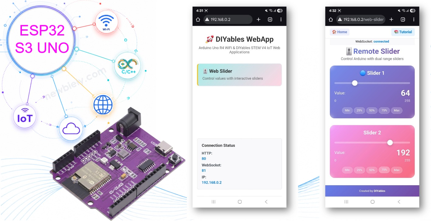
ESP32 S3 Uno web slider

Features

The slider page does the web work for you. Your sketch only gets two numbers and decides what to do with them.

Two independent sliders

Each slider has its own value from 0 to 255. You can use one for brightness and the other for speed, or anything else you like.

Real-time values over WebSocket

New values travel over WebSocket, so the board gets them the moment you move a slider. There is no page refresh. The page also shows the current number next to each slider.

Ready for PWM

The 0–255 range is 8-bit, the same range that analogWrite() takes. You can pass the value straight to a PWM pin without any math.

Preset buttons

Quick buttons set common values (0%, 25%, 50%, 75%, 100%) with one tap.

Works on any screen

Mouse and touch both work. The layout fits desktop, tablet and phone screens, and the sliders keep their last position when you reload the page.

Hardware Preparation

1×ESP32 S3 Uno-form Board
1×USB Cable Type-A to Type-C (for USB-A PC)
1×USB Cable Type-C to Type-C (for USB-C PC)

Or you can buy the following kits:

1×DIYables Sensor Kit (18 sensors/displays)
Disclosure: Some of the links provided in this section are Amazon affiliate links. We may receive a commission for any purchases made through these links at no additional cost to you.
Additionally, some of these links are for products from our own brand, DIYables .

Setup Instructions

The basic example needs no wiring. You only need the board, a USB cable and a WiFi network. Your phone or PC must be on the same WiFi network as the ESP32 S3 Uno.

Detailed Instructions

Follow these steps in order:

  1. New to the ESP32 S3 Uno? Follow ESP32 S3 Uno - Getting Started first.
  2. Connect the board to your computer with a USB Type-C cable.
  3. Open Arduino IDE, choose the ESP32S3 Dev Module board and the correct COM port.
  4. Open the Library Manager by clicking the Libraries icon on the left bar of Arduino IDE.
  5. Search for the library: type "DIYables ESP32 WebApps" and find the DIYables ESP32 WebApps library by DIYables.
  6. Install it by clicking the Install button.
  • Search for DIYables ESP32 WebApps created by DIYables and click the Install button.
∞
Newbiely | Arduino IDE 2.3.8
──
☐
✕
File
Edit
Sketch
Tools
Help
ESP32S3 Dev Module
Library Manager
Type:
All
Topic:
All
DIYables ESP32 WebApps by DIYables
A comprehensive library designed for ESP32 that provides multiple professional web applications including Web Monitor, Chat, Digital Pin Control, Sliders, Joystick, Analog Gauge, Rotator Control, and Temperature Display via WebSocket communication. Features modular architecture for memory efficiency, automatic config handling, and perfect for IoT projects, robotics, sensor monitoring, servo/stepper control, temperature monitoring, and remote ESP32 control. More info
1.0.1
INSTALL
Newbiely.ino
···
1 void setup() {
Output
Serial Monitor
Ln 1, Col 1
ESP32S3 Dev Module on COM15
1
  1. Install the dependencies: Arduino IDE asks to install some other libraries too. Click Install All.
  2. Open the example: go to File Examples DIYables ESP32 WebApps WebSlider, or copy the code below and paste it into Arduino IDE.
/* * DIYables WebApp Library - Web Slider Example * * This example demonstrates the Web Slider feature: * - Two independent sliders (0-255) * - Real-time value monitoring * - Template for hardware control * * Hardware: ESP32 S3 Uno * * Setup: * 1. Update WiFi credentials below * 2. Upload the sketch to your ESP32 S3 Uno * 3. Open Serial Monitor to see the IP address * 4. Navigate to http://[IP_ADDRESS]/webslider */ #include <DIYables_ESP32_Platform.h> #include <DIYablesWebApps.h> // WiFi credentials - UPDATE THESE WITH YOUR NETWORK const char WIFI_SSID[] = "YOUR_WIFI_SSID"; const char WIFI_PASSWORD[] = "YOUR_WIFI_PASSWORD"; // Create WebApp server and page instances ESP32ServerFactory serverFactory; DIYablesWebAppServer webAppsServer(serverFactory, 80, 81); DIYablesHomePage homePage; DIYablesWebSliderPage webSliderPage; // Current slider values int slider1Value = 64; // Default 25% int slider2Value = 128; // Default 50% void setup() { Serial.begin(9600); delay(1000); // TODO: Initialize your hardware pins here Serial.println("DIYables ESP32 WebApp - Web Slider Example"); // Add home and web slider pages webAppsServer.addApp(&homePage); webAppsServer.addApp(&webSliderPage); // Optional: Add 404 page for better user experience webAppsServer.setNotFoundPage(DIYablesNotFoundPage()); // Start the WebApp server if (!webAppsServer.begin(WIFI_SSID, WIFI_PASSWORD)) { while (1) { Serial.println("Failed to start WebApp server!"); delay(1000); } } // Set up slider callback for value changes webSliderPage.onSliderValueFromWeb([](int slider1, int slider2) { // Store the received values slider1Value = slider1; slider2Value = slider2; // Print slider values (0-255) Serial.println("Slider 1: " + String(slider1) + ", Slider 2: " + String(slider2)); // TODO: Add your control logic here based on slider values // Examples: // - Control PWM: analogWrite(LED_PIN, slider1); // - Control servos: servo.write(map(slider1, 0, 255, 0, 180)); // - Control motor speed: analogWrite(MOTOR_PIN, slider2); // - Control brightness: strip.setBrightness(slider1); // - Send values via Serial, I2C, SPI, etc. }); // Set up callback for config requests (when client requests current values) webSliderPage.onSliderValueToWeb([]() { webSliderPage.sendToWebSlider(slider1Value, slider2Value); Serial.println("Web client requested values - Sent: Slider1=" + String(slider1Value) + ", Slider2=" + String(slider2Value)); }); } void loop() { // Handle WebApp server communications webAppsServer.loop(); // TODO: Add your main application code here delay(10); }
  1. Add your WiFi details by changing these two lines:
const char WIFI_SSID[] = "YOUR_WIFI_SSID"; const char WIFI_PASSWORD[] = "YOUR_WIFI_PASSWORD";
  1. Upload the code: click the Upload button in Arduino IDE to send the sketch to the ESP32 S3 Uno.
  2. Open the Serial Monitor and set it to 9600 baud. You should see output like this:
∞
Newbiely | Arduino IDE 2.3.8
──
☐
✕
File
Edit
Sketch
Tools
Help
ESP32S3 Dev Module
Newbiely.ino
···
8 Serial.println("Hello World!");
Output
Serial Monitor
Message (Enter to send message to 'ESP32S3 Dev Module' on 'COM15')
New Line
9600 baud
DIYables ESP32 WebApp - Web Slider Example INFO: Added app / INFO: Added app /web-slider DIYables WebApp Library Platform: ESP32 Network connected! IP address: 192.168.0.2 HTTP server started on port 80 Configuring WebSocket server callbacks... WebSocket server started on port 81 WebSocket URL: ws://192.168.0.2:81 WebSocket server started on port 81 ========================================== DIYables WebApp Ready! ========================================== 📱 Web Interface: http://192.168.0.2 🔗 WebSocket: ws://192.168.0.2:81 📋 Available Applications: 🏠 Home Page: http://192.168.0.2/ 🎚️ Web Slider: http://192.168.0.2/web-slider ==========================================
Ln 11, Col 1
ESP32S3 Dev Module on COM15
2
  1. No output? Press the RESET button on the board once and watch the Serial Monitor again.
  2. Open a web browser on your PC or phone and type the IP address from the Serial Monitor, for example http://192.168.0.2. The home page appears:
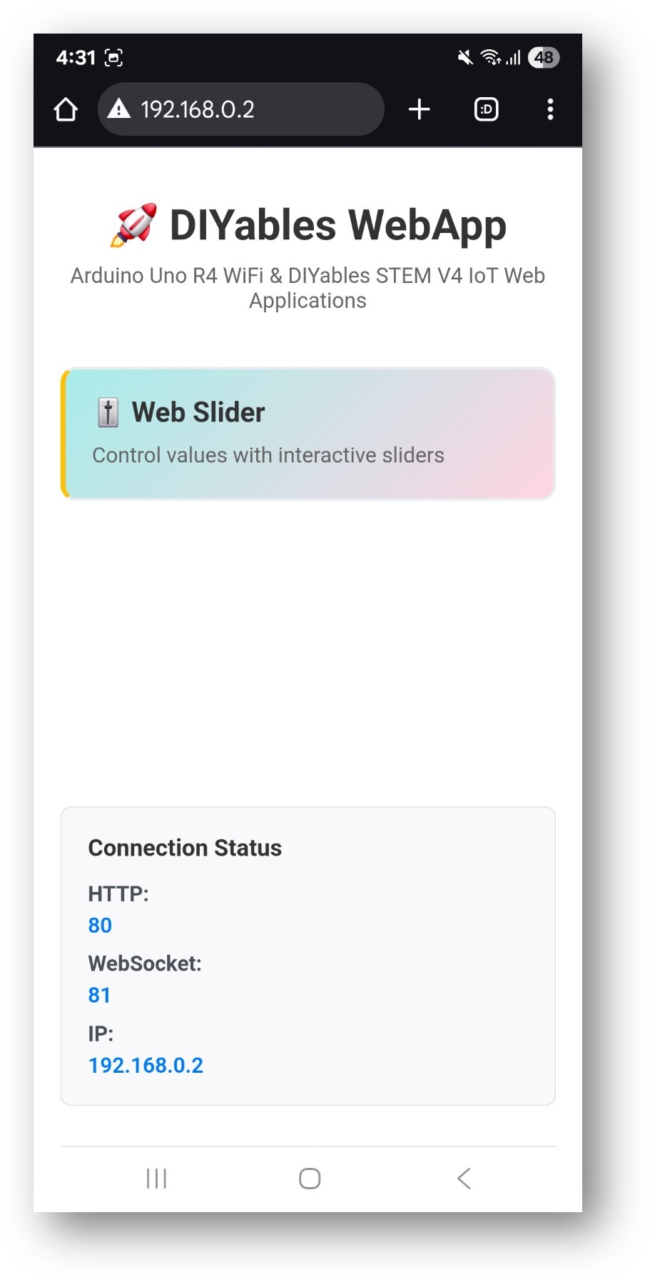
ESP32 S3 Uno DIYables WebApp Home page with Web Slider app
  1. Click the Web Slider link to open the slider page:
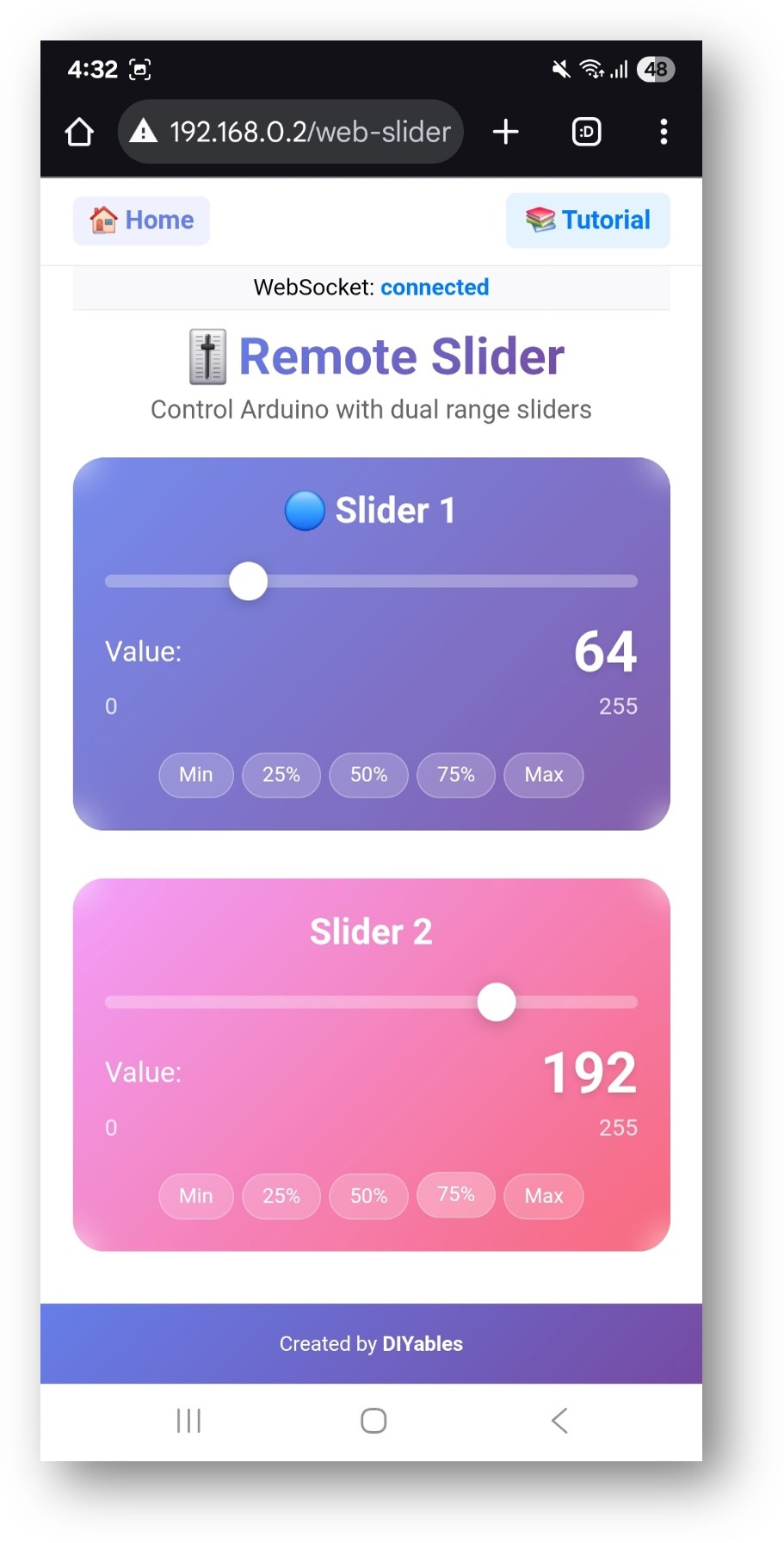
ESP32 S3 Uno DIYables WebApp Web Slider app
  1. Move the two sliders and watch the new values (0–255) appear in the Serial Monitor:
∞
Newbiely | Arduino IDE 2.3.8
──
☐
✕
File
Edit
Sketch
Tools
Help
ESP32S3 Dev Module
Newbiely.ino
···
8 Serial.println("Hello World!");
Output
Serial Monitor
Message (Enter to send message to 'ESP32S3 Dev Module' on 'COM15')
New Line
9600 baud
Web client requested values - Sent: Slider1=64, Slider2=128 Slider 1: 90, Slider 2: 128 Slider 1: 155, Slider 2: 128 Slider 1: 155, Slider 2: 210 Slider 1: 255, Slider 2: 210
Ln 11, Col 1
ESP32S3 Dev Module on COM15
2
  1. Tip: you can skip the home page and open the sliders directly with the IP address plus /web-slider, for example http://192.168.0.2/web-slider. Bookmark it on your phone for quick access.

Creative Customization - Adapt the Code to Your Project

The example is a template. You keep the web part as it is and only change the start values and what happens when a value arrives.

Set Default Slider Values

These two variables hold the slider positions when the board starts. The page reads them when it first connects, so the sliders open at these positions:

// Current slider values (0-255) int slider1Value = 64; // Default 25% (64/255) int slider2Value = 128; // Default 50% (128/255)

How to Use the Sliders

The page is simple, but a few details help you set exact values. This part explains the controls and the value range.

Web Interface Controls

The page has two sliders, Slider 1 and Slider 2. Each one shows its current number (0–255) next to it, so you always know the exact value. Below them, preset buttons jump to 0%, 25%, 50%, 75% or 100% in one tap.

Operating the Sliders

Desktop (Mouse Control)

  1. Click and drag the slider handle to change the value.
  2. Click on the track to jump straight to that position.
  3. Move the mouse slowly when you need a precise value.

Mobile/Tablet (Touch Control)

  1. Touch and drag the handle to a new position.
  2. Tap on the track to set the value at that point.
  3. Slide your finger for smooth changes.

Value Ranges

Each slider goes from 0 (0%, fully off) to 255 (100%, full power). That gives 256 steps, which is 8-bit resolution. Because analogWrite() on the ESP32 S3 Uno also uses a 0–255 range by default, you can pass the slider value straight to a PWM pin.

Programming Examples

The snippets below show common ways to use the two values. Each one goes inside the full WebSlider sketch above: keep the WiFi, server and page setup, and replace the callback part. All pin numbers are GPIO numbers for the ESP32 S3 Uno, with the Uno header label in the comments.

WARNING

Several examples use D9, which is GPIO46 on the ESP32 S3 Uno. GPIO46 is a boot strapping pin. The board reads it at power-up to choose the boot mode. If a part on this pin pulls it HIGH during reset, the board may not boot or may fail to upload code. LEDs through a resistor and servo signal lines are usually fine. If you see boot or upload problems, unplug the wire from D9, upload, then plug it back in.

Basic Slider Handler

This is the smallest handler. It saves both values and prints them, so you can see the data before you add any hardware.

void setup() { // Set up slider callback for value changes webSliderPage.onSliderValueFromWeb([](int slider1, int slider2) { // Store the received values slider1Value = slider1; slider2Value = slider2; // Print slider values (0-255) Serial.println("Slider 1: " + String(slider1) + ", Slider 2: " + String(slider2)); // Add your control logic here }); }

LED Brightness Control

Two LEDs, one per slider. The slider value goes straight into analogWrite(), so 0 turns the LED off and 255 gives full brightness. Use a 220 ohm resistor in series with each LED.

// Pin definitions for PWM LEDs const int LED1_PIN = 46; // D9 (GPIO46) - PWM pin for first LED const int LED2_PIN = 10; // D10 (GPIO10) - PWM pin for second LED void setup() { // Configure LED pins as outputs pinMode(LED1_PIN, OUTPUT); pinMode(LED2_PIN, OUTPUT); // Set initial brightness analogWrite(LED1_PIN, slider1Value); analogWrite(LED2_PIN, slider2Value); webSliderPage.onSliderValueFromWeb([](int slider1, int slider2) { // Store values slider1Value = slider1; slider2Value = slider2; // Control LED brightness directly (0-255 PWM) analogWrite(LED1_PIN, slider1); analogWrite(LED2_PIN, slider2); Serial.println("LED1 Brightness: " + String(slider1) + ", LED2 Brightness: " + String(slider2)); }); }

Servo Position Control

Here map() turns the 0–255 slider range into a 0–180° servo angle. On the ESP32 S3 Uno you need the ESP32Servo library (by Kevin Harrington) instead of the standard Servo library. Install it from the Library Manager first.

#include <ESP32Servo.h> Servo servo1, servo2; void setup() { // Attach servos to PWM pins servo1.attach(46); // D9 (GPIO46) servo2.attach(10); // D10 (GPIO10) // Set initial positions servo1.write(map(slider1Value, 0, 255, 0, 180)); servo2.write(map(slider2Value, 0, 255, 0, 180)); webSliderPage.onSliderValueFromWeb([](int slider1, int slider2) { slider1Value = slider1; slider2Value = slider2; // Map slider values (0-255) to servo angles (0-180°) int angle1 = map(slider1, 0, 255, 0, 180); int angle2 = map(slider2, 0, 255, 0, 180); // Move servos to calculated positions servo1.write(angle1); servo2.write(angle2); Serial.println("Servo1: " + String(angle1) + "°, Servo2: " + String(angle2) + "°"); }); }

Motor Speed Control

This example drives two DC motors through a motor driver such as the L298N. The direction pins are set to "forward" once, and each slider sets the PWM speed of one motor. The sketch also prints the speed as a percentage.

// Motor driver pins const int MOTOR1_PWM = 46; // D9 (GPIO46) - Motor 1 speed control const int MOTOR1_DIR1 = 18; // D2 (GPIO18) - Motor 1 direction pin 1 const int MOTOR1_DIR2 = 17; // D3 (GPIO17) - Motor 1 direction pin 2 const int MOTOR2_PWM = 10; // D10 (GPIO10) - Motor 2 speed control const int MOTOR2_DIR1 = 19; // D4 (GPIO19) - Motor 2 direction pin 1 const int MOTOR2_DIR2 = 20; // D5 (GPIO20) - Motor 2 direction pin 2 void setup() { // Configure motor pins pinMode(MOTOR1_PWM, OUTPUT); pinMode(MOTOR1_DIR1, OUTPUT); pinMode(MOTOR1_DIR2, OUTPUT); pinMode(MOTOR2_PWM, OUTPUT); pinMode(MOTOR2_DIR1, OUTPUT); pinMode(MOTOR2_DIR2, OUTPUT); // Set initial motor directions (forward) digitalWrite(MOTOR1_DIR1, HIGH); digitalWrite(MOTOR1_DIR2, LOW); digitalWrite(MOTOR2_DIR1, HIGH); digitalWrite(MOTOR2_DIR2, LOW); webSliderPage.onSliderValueFromWeb([](int slider1, int slider2) { slider1Value = slider1; slider2Value = slider2; // Control motor speeds directly analogWrite(MOTOR1_PWM, slider1); analogWrite(MOTOR2_PWM, slider2); // Calculate percentage for display int speed1Percent = map(slider1, 0, 255, 0, 100); int speed2Percent = map(slider2, 0, 255, 0, 100); Serial.println("Motor1: " + String(speed1Percent) + "%, " + "Motor2: " + String(speed2Percent) + "%"); }); }

RGB LED Color Control

With only two sliders you cannot set three colors one by one, so this example uses a trick. Slider 1 sets red, slider 2 sets blue, and green is the average of the two.

// RGB LED pins const int RED_PIN = 46; // D9 (GPIO46) const int GREEN_PIN = 10; // D10 (GPIO10) const int BLUE_PIN = 11; // D11 (GPIO11) void setup() { pinMode(RED_PIN, OUTPUT); pinMode(GREEN_PIN, OUTPUT); pinMode(BLUE_PIN, OUTPUT); webSliderPage.onSliderValueFromWeb([](int slider1, int slider2) { slider1Value = slider1; slider2Value = slider2; // Use sliders to control RGB components // Slider 1 controls red intensity // Slider 2 controls blue intensity // Green is calculated based on both sliders int redValue = slider1; int blueValue = slider2; int greenValue = (slider1 + slider2) / 2; // Average of both sliders analogWrite(RED_PIN, redValue); analogWrite(GREEN_PIN, greenValue); analogWrite(BLUE_PIN, blueValue); Serial.println("RGB - R:" + String(redValue) + " G:" + String(greenValue) + " B:" + String(blueValue)); }); }

Advanced Programming Techniques

Raw slider values can jump fast, which is hard on motors and looks rough on lights. These techniques give you smoother and smarter control.

Value Smoothing

The SliderSmoother class moves the output toward the target in small steps (5 units every 10 ms) instead of jumping at once. The callback only sets the target, and loop() applies the smoothed value to the hardware.

class SliderSmoother { private: int currentValue = 0; int targetValue = 0; unsigned long lastUpdate = 0; const int SMOOTH_RATE = 5; // Change per update cycle public: void setTarget(int target) { targetValue = target; } int getCurrentValue() { return currentValue; } bool update() { if (millis() - lastUpdate > 10) { // Update every 10ms bool changed = false; if (currentValue < targetValue) { currentValue = min(currentValue + SMOOTH_RATE, targetValue); changed = true; } else if (currentValue > targetValue) { currentValue = max(currentValue - SMOOTH_RATE, targetValue); changed = true; } lastUpdate = millis(); return changed; } return false; } }; SliderSmoother smoother1, smoother2; void setup() { webSliderPage.onSliderValueFromWeb([](int slider1, int slider2) { // Set target values for smooth transition smoother1.setTarget(slider1); smoother2.setTarget(slider2); }); } void loop() { webAppsServer.loop(); // Update smoothed values bool changed1 = smoother1.update(); bool changed2 = smoother2.update(); if (changed1 || changed2) { // Apply smoothed values to hardware analogWrite(46, smoother1.getCurrentValue()); // D9 (GPIO46) analogWrite(10, smoother2.getCurrentValue()); // D10 (GPIO10) } }

Threshold-Based Control

Sometimes you want steps, not a smooth range. Here slider 1 is split into three levels (below 85, below 170, and above). Each level turns a different set of digital outputs on. Slider 2 still drives a PWM pin.

void setupThresholdControl() { webSliderPage.onSliderValueFromWeb([](int slider1, int slider2) { slider1Value = slider1; slider2Value = slider2; // Threshold-based control for discrete outputs const int LOW_THRESHOLD = 85; // 33% const int MEDIUM_THRESHOLD = 170; // 66% // Control digital outputs based on slider 1 thresholds // GPIO18 = D2, GPIO17 = D3, GPIO19 = D4 if (slider1 < LOW_THRESHOLD) { // Low level: Turn off all outputs digitalWrite(18, LOW); digitalWrite(17, LOW); digitalWrite(19, LOW); } else if (slider1 < MEDIUM_THRESHOLD) { // Medium level: Turn on first output digitalWrite(18, HIGH); digitalWrite(17, LOW); digitalWrite(19, LOW); } else { // High level: Turn on all outputs digitalWrite(18, HIGH); digitalWrite(17, HIGH); digitalWrite(19, HIGH); } // Use slider 2 for analog PWM control analogWrite(46, slider2); // D9 (GPIO46) }); }

Preset Value System

Presets let you jump to saved settings with a push button. Each press of the button on D7 loads the next preset, updates the PWM outputs, and calls sendToWebSlider() so the sliders on the web page move to the new values too.

// Predefined preset values const int PRESETS[][2] = { {0, 0}, // Preset 0: Both off {64, 128}, // Preset 1: Low/Medium {128, 128}, // Preset 2: Both medium {255, 128}, // Preset 3: High/Medium {255, 255} // Preset 4: Both maximum }; void applyPreset(int presetNumber) { if (presetNumber >= 0 && presetNumber < 5) { slider1Value = PRESETS[presetNumber][0]; slider2Value = PRESETS[presetNumber][1]; // Update hardware analogWrite(46, slider1Value); // D9 (GPIO46) analogWrite(10, slider2Value); // D10 (GPIO10) // Send updated values to web interface webSliderPage.sendToWebSlider(slider1Value, slider2Value); Serial.println("Applied preset " + String(presetNumber) + ": " + String(slider1Value) + ", " + String(slider2Value)); } } void setupPresetSystem() { // You could trigger presets based on other inputs // For example, reading digital pins for preset buttons webSliderPage.onSliderValueFromWeb([](int slider1, int slider2) { slider1Value = slider1; slider2Value = slider2; // Your normal slider handling analogWrite(46, slider1); // D9 (GPIO46) analogWrite(10, slider2); // D10 (GPIO10) }); } void loop() { webAppsServer.loop(); // Check for preset trigger conditions // Example: Read buttons connected to digital pins static bool lastButton = false; bool currentButton = digitalRead(14); // Preset button on D7 (GPIO14) if (currentButton && !lastButton) { // Button pressed static int currentPreset = 0; applyPreset(currentPreset); currentPreset = (currentPreset + 1) % 5; // Cycle through presets } lastButton = currentButton; }

Hardware Integration Examples

These sketches connect the sliders to real devices. Remember that ESP32 S3 Uno pins are 3.3V and NOT 5V tolerant, and they cannot drive motors, fans or LED strips directly. Use a driver, a transistor or a MOSFET module between the pin and the load.

LED Strip Control

For a WS2812B (NeoPixel) strip, slider 1 can set brightness and slider 2 the hue. The strip calls are left as comments because they depend on the library you pick, FastLED or Adafruit NeoPixel.

// For WS2812B or similar addressable LED strips // (requires additional libraries like FastLED or Adafruit NeoPixel) const int LED_STRIP_PIN = 3; // D6 (GPIO3) const int NUM_LEDS = 30; void setupLEDStrip() { // Initialize LED strip (depends on library used) webSliderPage.onSliderValueFromWeb([](int slider1, int slider2) { slider1Value = slider1; slider2Value = slider2; // Slider 1 controls brightness (0-255) // Slider 2 controls color temperature or hue uint8_t brightness = slider1; uint8_t hue = slider2; // Update LED strip (example with conceptual functions) // strip.setBrightness(brightness); // strip.fill(CHSV(hue, 255, 255)); // strip.show(); Serial.println("LED Strip - Brightness: " + String(brightness) + ", Hue: " + String(hue)); }); }

WARNING

The LED strip data pin is D6, which is GPIO3 on the ESP32 S3 Uno. GPIO3 is a boot strapping pin, so a strip that holds this line at a fixed level during reset can stop the board from booting or uploading. If that happens, unplug the data wire while you upload. Also note that a WS2812B strip runs on 5V. The 3.3V data signal works with many strips, but a level shifter makes it reliable.

Fan Speed Control

Small fans often do not start at a low PWM value. This code ignores slider values below 50 and maps the rest to a PWM range of 100–255, so the fan either stays off or spins for sure.

const int FAN1_PIN = 46; // D9 (GPIO46) const int FAN2_PIN = 10; // D10 (GPIO10) void setupFanControl() { pinMode(FAN1_PIN, OUTPUT); pinMode(FAN2_PIN, OUTPUT); webSliderPage.onSliderValueFromWeb([](int slider1, int slider2) { slider1Value = slider1; slider2Value = slider2; // Control fan speeds with minimum threshold for startup int fan1Speed = (slider1 > 50) ? map(slider1, 50, 255, 100, 255) : 0; int fan2Speed = (slider2 > 50) ? map(slider2, 50, 255, 100, 255) : 0; analogWrite(FAN1_PIN, fan1Speed); analogWrite(FAN2_PIN, fan2Speed); Serial.println("Fan1: " + String(map(fan1Speed, 0, 255, 0, 100)) + "%, " + "Fan2: " + String(map(fan2Speed, 0, 255, 0, 100)) + "%"); }); }

Audio Volume Control

Our ears do not hear loudness in a straight line. This example squares the slider value, so the low end of the slider gives finer control and the volume change feels more natural.

// For controlling audio amplifier or volume IC const int VOLUME1_PIN = 46; // D9 (GPIO46) - PWM output to volume control const int VOLUME2_PIN = 10; // D10 (GPIO10) - Second channel or tone control void setupAudioControl() { pinMode(VOLUME1_PIN, OUTPUT); pinMode(VOLUME2_PIN, OUTPUT); webSliderPage.onSliderValueFromWeb([](int slider1, int slider2) { slider1Value = slider1; slider2Value = slider2; // Use logarithmic scaling for better audio perception float volume1 = pow(slider1 / 255.0, 2) * 255; // Square law float volume2 = pow(slider2 / 255.0, 2) * 255; analogWrite(VOLUME1_PIN, (int)volume1); analogWrite(VOLUME2_PIN, (int)volume2); Serial.println("Volume1: " + String((int)volume1) + ", Volume2: " + String((int)volume2)); }); }

Common Issues and Debug Tips

Most slider problems come from the network link or from the pin setup. Check these points before you change your code.

Common Issues

Sliders do not respond

Open the browser console and check the WebSocket connection. Make sure the phone or PC and the ESP32 S3 Uno are on the same network. Refresh the page to reconnect, and look at the Serial Monitor for connection errors.

Values do not reach the full range

Check any map() calls in your callback for wrong numbers. Try another browser or device to rule out a display issue.

Control feels jerky

Use the value smoothing class above for slow, even changes. A weak WiFi signal adds delay, so move the board closer to the router if needed.

PWM output does nothing

Check the ESP32 S3 Uno pinout to confirm the GPIO number. Make sure analogWrite() uses the GPIO number (for example 10), not the label D10. Check the wiring and make sure the load does not draw more current than the pin can give.

Debug Tips

Add this helper to print both values as raw numbers and as percentages:

void debugSliderValues(int slider1, int slider2) { Serial.println("=== Slider Debug ==="); Serial.println("Slider 1: " + String(slider1) + " (" + String(map(slider1, 0, 255, 0, 100)) + "%)"); Serial.println("Slider 2: " + String(slider2) + " (" + String(map(slider2, 0, 255, 0, 100)) + "%)"); Serial.println("PWM Pin D9 (GPIO46): " + String(slider1)); Serial.println("PWM Pin D10 (GPIO10): " + String(slider2)); Serial.println("==================="); }

Project Ideas

Two sliders are enough for many real projects. Here are some ideas to start from.

Lighting control

Dim room lights, mix colors on an RGB LED, set the speed of an LED strip animation, or control stage light intensity.

Motor control

Set robot speed, fan speed, pump flow, or the speed of a small conveyor belt.

Audio

Build a volume control, a tone or equalizer control, or set the strength of a sound effect or a music visualizer.

Home automation

Set heating or cooling power, window blind position, irrigation flow, or the brightness and volume of smart devices.

Integration with Other Examples

The WebSlider page can run together with other DIYables ESP32 WebApps pages on the same board. These two combos are a good start.

Combine with WebJoystick

The joystick gives the direction, and slider 1 sets the top speed:

// Global speed limit from sliders int maxSpeed = 255; // In WebSlider callback webSliderPage.onSliderValueFromWeb([](int slider1, int slider2) { maxSpeed = slider1; // Use slider 1 as global speed limit }); // In WebJoystick callback webJoystickPage.onJoystickValueFromWeb([](int x, int y) { // Scale joystick values by slider-controlled speed limit int scaledX = map(x, -100, 100, -maxSpeed, maxSpeed); int scaledY = map(y, -100, 100, -maxSpeed, maxSpeed); controlRobot(scaledX, scaledY); });

Combine with WebDigitalPins

The digital pins page works as an on/off switch, and the sliders set the PWM level only while the switch is on:

webSliderPage.onSliderValueFromWeb([](int slider1, int slider2) { // Only apply PWM if corresponding digital pins are ON if (webDigitalPinsPage.getPinState(18)) { // D2 (GPIO18) analogWrite(46, slider1); // D9 (GPIO46) } else { analogWrite(46, 0); } if (webDigitalPinsPage.getPinState(17)) { // D3 (GPIO17) analogWrite(10, slider2); // D10 (GPIO10) } else { analogWrite(10, 0); } });

ESP32 S3 Uno Pinout

The image below shows the pinout diagram of the ESP32 S3 Uno form board. Use it to find the D3 and D5 header pins and their GPIO numbers before you wire the servos for the video demo.

ESP32 S3 Uno pinout diagram

Video Tutorial

Watch the video below to see this ESP32 S3 Uno project step by step. In the demo, each slider moves one servo motor from 0° to 180°.

Wire the two servo motors like this:

Servo Pin ESP32 S3 Uno Pin
Servo 1 signal (orange) D3 (GPIO17)
Servo 2 signal (orange) D5 (GPIO20)
Both VCC (red) 5V
Both GND (brown) GND

The demo sketch uses the ESP32Servo library, so install it from the Library Manager before you upload. Remember to put your own WiFi name and password in the code.

/* * This ESP32 S3 Uno code was developed by newbiely.com * * This ESP32 S3 Uno code is made available for public use without any restriction * * For comprehensive instructions and wiring diagrams, please visit: * https://newbiely.com/tutorials/esp32-s3-uno/diyables-web-apps-web-slider */ /* * DIYables WebApp Library - Web Slider Example * * This example demonstrates the Web Slider feature: * - Two independent sliders (0-255) * - Real-time value monitoring * - Template for hardware control * * Hardware: ESP32 S3 Uno, 2 x servo motors (signal on D3 and D5) * * Setup: * 1. Update WiFi credentials below * 2. Upload the sketch to your ESP32 S3 Uno * 3. Open Serial Monitor to see the IP address * 4. Navigate to http://[IP_ADDRESS]/webslider */ #include <DIYables_ESP32_Platform.h> #include <DIYablesWebApps.h> #include <ESP32Servo.h> Servo servo1, servo2; // WiFi credentials - UPDATE THESE WITH YOUR NETWORK const char WIFI_SSID[] = "YOUR_WIFI_SSID"; const char WIFI_PASSWORD[] = "YOUR_WIFI_PASSWORD"; // Create WebApp server and page instances ESP32ServerFactory serverFactory; DIYablesWebAppServer webAppsServer(serverFactory, 80, 81); DIYablesHomePage homePage; DIYablesWebSliderPage webSliderPage; // Current slider values int slider1Value = 64; // Default 25% int slider2Value = 128; // Default 50% void setup() { Serial.begin(9600); delay(1000); // TODO: Initialize your hardware pins here servo1.attach(17); // D3 (GPIO17) servo2.attach(20); // D5 (GPIO20) Serial.println("DIYables ESP32 WebApp - Web Slider Example"); // Add home and web slider pages webAppsServer.addApp(&homePage); webAppsServer.addApp(&webSliderPage); // Optional: Add 404 page for better user experience webAppsServer.setNotFoundPage(DIYablesNotFoundPage()); // Start the WebApp server if (!webAppsServer.begin(WIFI_SSID, WIFI_PASSWORD)) { while (1) { Serial.println("Failed to start WebApp server!"); delay(1000); } } // Set initial positions servo1.write(map(slider1Value, 0, 255, 0, 180)); servo2.write(map(slider2Value, 0, 255, 0, 180)); webSliderPage.onSliderValueFromWeb([](int slider1, int slider2) { slider1Value = slider1; slider2Value = slider2; // Map slider values (0-255) to servo angles (0-180°) int angle1 = map(slider1, 0, 255, 0, 180); int angle2 = map(slider2, 0, 255, 0, 180); // Move servos to calculated positions servo1.write(angle1); servo2.write(angle2); Serial.println("Servo1: " + String(angle1) + "°, Servo2: " + String(angle2) + "°"); }); // Set up callback for config requests (when client requests current values) webSliderPage.onSliderValueToWeb([]() { webSliderPage.sendToWebSlider(slider1Value, slider2Value); Serial.println("Web client requested values - Sent: Slider1=" + String(slider1Value) + ", Slider2=" + String(slider2Value)); }); } void loop() { // Handle WebApp server communications webAppsServer.loop(); // TODO: Add your main application code here delay(10); }

Next Steps

Once the sliders work, try these examples next:

  1. WebJoystick for 2D direction control
  2. WebDigitalPins for simple on/off control
  3. WebMonitor to debug slider values in the browser
  4. MultipleWebApps to put sliders and other controls on one board

Support

For more help, check the library API reference. You can also read the ESP32 S3 Uno DIYables Web Apps overview, or ask in the Arduino community forums.

FAQ

Can I use the slider value directly with analogWrite() on the ESP32 S3 Uno?

Yes. The esp32 by Espressif Systems board package supports analogWrite() and uses an 8-bit range (0–255) by default. The slider sends 0–255, so you can pass the value straight in. Write the GPIO number, for example analogWrite(10, slider1) for D10.

Which ESP32 S3 Uno pins can I use for PWM?

Every Uno header pin from D2 to D13 supports PWM. Avoid D0 and D1, because they are used for USB serial. D6 (GPIO3) and D9 (GPIO46) also work, but they are boot strapping pins, so a part that pulls them HIGH or LOW at reset can stop the board from booting.

Why does the servo example use ESP32Servo.h instead of Servo.h?

The standard Servo library does not support the ESP32 S3 Uno. ESP32Servo by Kevin Harrington gives you the same Servo class with attach() and write(), so the rest of the code stays the same. Install it from the Library Manager.

Is this library the same as the DIYables WebApps library for the UNO R4 WiFi?

No. The ESP32 S3 Uno uses the "DIYables ESP32 WebApps" library and includes DIYables_ESP32_Platform.h with ESP32ServerFactory. The page classes and callbacks, like DIYablesWebSliderPage and onSliderValueFromWeb(), work the same way, so most UNO R4 code moves over easily.

Can I control a 5V device with the slider?

The ESP32 S3 Uno pins put out 3.3V and are NOT 5V tolerant. A servo or a 5V LED strip usually accepts a 3.3V signal. For motors, fans and lamps, use a driver board, a transistor or a MOSFET module, and never feed a 5V signal back into an ESP32 S3 Uno pin.

What if my project needs more pins than the Uno headers give?

The ESP32 S3 Uno has two extra rows of holes with more GPIOs: GPIO15 and GPIO16 (I/O, PWM, analog), GPIO45 and GPIO35–GPIO42 (I/O, PWM), and GPIO47/GPIO48 (output only, PWM). Solder pin headers to use them and write the GPIO number in code. For extra PWM outputs like LEDs or servos, GPIO35–GPIO42 and GPIO15/GPIO16 are good picks. Be careful with two things. First, GPIO47/GPIO48 may run at 1.8V instead of 3.3V on some modules (especially ones with "V" in the name, like R8V or R16V), so 3.3V devices can be damaged or act strangely. Second, GPIO0, GPIO3 (D6), GPIO45 and GPIO46 (D9) are boot strapping pins, and a wrong connection can stop the board from booting or uploading code. Use the other extra pins first.

Troubleshooting

Problem Possible Cause Solution
No COM port in Arduino IDE Missing USB driver or the board is not in upload mode Install the CP210x or CH340 driver, or hold BOOT while you press RESET, then upload again
Serial Monitor shows "Failed to start WebApp server!" Wrong WiFi name or password, or a 5 GHz only network Check the SSID and password and use a 2.4 GHz WiFi network
Web page does not open Phone or PC is on another network, or the IP address is wrong Join the same WiFi network and use the IP address printed in the Serial Monitor
Slider moves but the LED does not change LED wired to the wrong pin or the code uses the D label Use the GPIO number in code (D10 is 10) and check the LED polarity and resistor
Board does not boot or upload with parts attached A part on D9 (GPIO46) or D6 (GPIO3) holds a strapping pin at reset Unplug that wire while you upload, or move the part to another free pin
Servos jitter or the board resets Servos draw too much current from the board Power the servos from a separate 5V supply and connect its GND to the board GND
Servo sketch does not compile The standard Servo library is used Install ESP32Servo and use #include

※ OUR MESSAGES

  • As freelancers, We are AVAILABLE for HIRE. See how to outsource your project to us
  • Please feel free to share the link of this tutorial. However, Please do not use our content on any other websites. We invested a lot of effort and time to create the content, please respect our work!