
ESP32 S3 UNO - Getting Started
This ESP32 S3 Uno getting started guide takes you from a new board to your first running program. You will set up the Arduino IDE, add the ESP32 board package, and upload a Hello World sketch to the ESP32 S3 Uno form board. At the end, you will see your board talk to you in the Serial Monitor.
In this tutorial, you will:
- Learn what the ESP32 S3 Uno is and how its pins map to GPIO numbers
- Install the Arduino IDE and the "esp32 by Espressif Systems" package
- Select the ESP32S3 Dev Module board and the COM port
- Upload your first sketch and read its output in the Serial Monitor
Hardware Preparation
| 1 | × | ESP32 S3 Uno-form Board | |
| 1 | × | USB Cable Type-A to Type-C (for USB-A PC) | |
| 1 | × | USB Cable Type-C to Type-C (for USB-C PC) |
Or you can buy the following kits:
| 1 | × | DIYables Sensor Kit (18 sensors/displays) |
Additionally, some of these links are for products from our own brand, DIYables .
Overview of the ESP32 S3 Uno
The ESP32 S3 Uno puts a powerful Espressif chip on a board with the classic Uno shape. You get WiFi, Bluetooth Low Energy and a fast dual-core CPU, but you keep the familiar Uno header layout. This makes it a good next step if you already know the Arduino Uno.
The Uno shape does not mean it works like an Arduino Uno inside. It uses a different chip, a different board package, and 3.3V logic. Keep these three points in mind, and most problems never happen.
Key Specifications
| Feature | ESP32 S3 Uno |
|---|---|
| Processor | Dual-core Xtensa LX7, up to 240 MHz |
| SRAM | 512 KB |
| Flash / PSRAM | Depends on the module (for example 16 MB flash + 8 MB PSRAM on N16R8) |
| WiFi | 2.4 GHz, 802.11 b/g/n |
| Bluetooth | Bluetooth 5 Low Energy (no Bluetooth Classic) |
| Logic level | 3.3V (pins are NOT 5V tolerant) |
| ADC | 12-bit (0 to 4095) |
| USB | USB Type-C |
| Board form | Arduino Uno shape and header layout |
ESP32 S3 Uno vs Arduino Uno
The headers sit in the same places, so many Uno shields fit on the board. But the code is not always the same. Here are the main differences:
- Logic voltage: the ESP32 S3 Uno uses 3.3V. A 5V signal can damage a pin.
- Analog range: analogRead() returns 0 to 4095, not 0 to 1023.
- I2C pins: A4 and A5 are NOT I2C on this board. Use the SDA and SCL header pins.
- Pin numbers in code: you write the GPIO number (for example 14), not D7.
- Libraries: some libraries change. For example, Servo.h becomes ESP32Servo.h, and SoftwareSerial is replaced by Serial1 or Serial2.
ESP32 S3 Uno Pinout
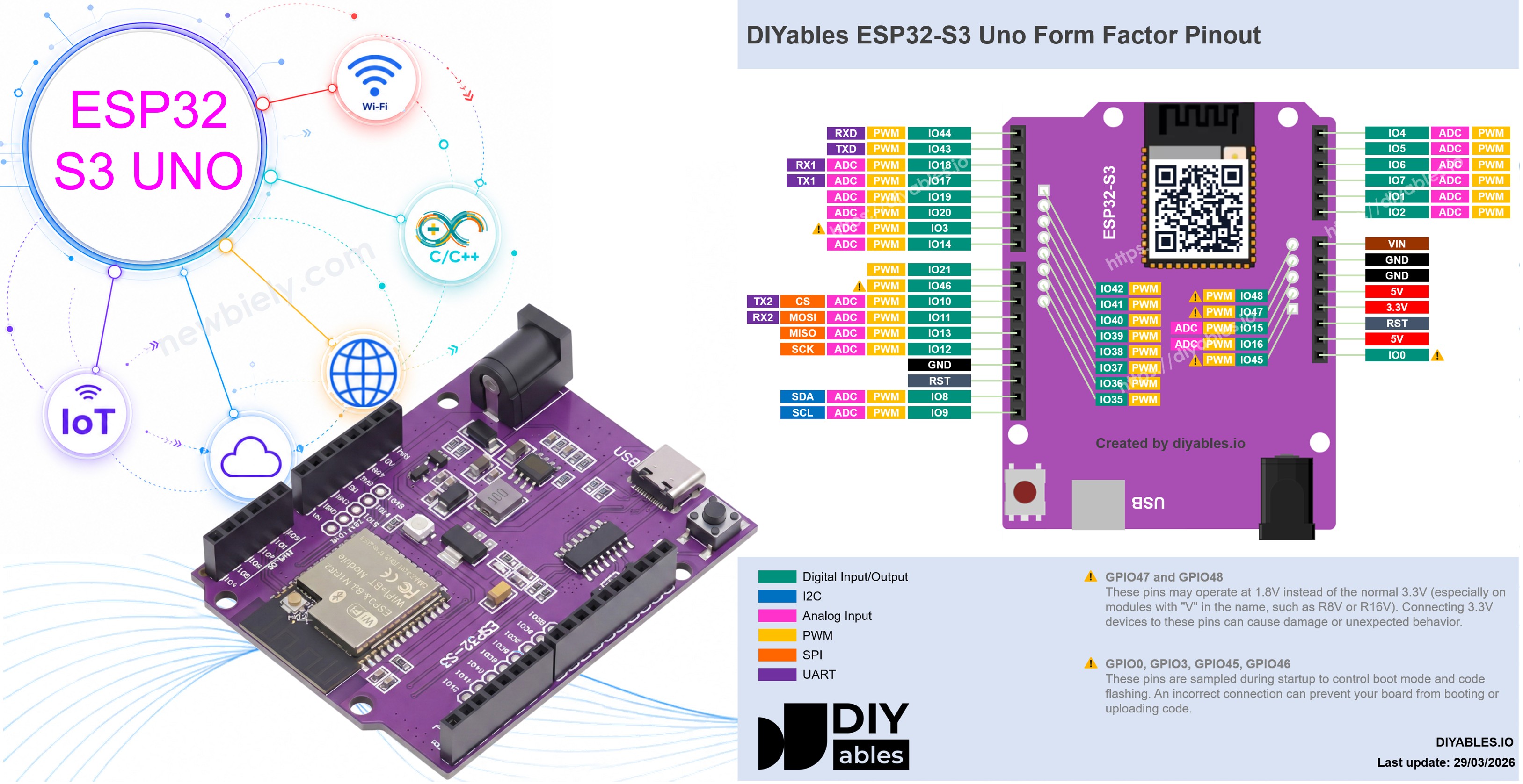
The pinout is the most useful image to keep close by. Each Uno header pin (D2, A0, SDA…) is connected to an ESP32 S3 Uno GPIO, and your code always uses the GPIO number.

The table below shows how the Uno header labels map to GPIO numbers.
| Uno Header | GPIO in Code | Functions |
|---|---|---|
| D0 (RX) | 44 | UART0 RX (used by USB serial, avoid) |
| D1 (TX) | 43 | UART0 TX (used by USB serial, avoid) |
| D2 | 18 | I/O, PWM, Analog, RX1 |
| D3 | 17 | I/O, PWM, Analog, TX1 |
| D4 | 19 | I/O, PWM, Analog |
| D5 | 20 | I/O, PWM, Analog |
| D6 | 3 | I/O, PWM, Analog (boot strapping pin) |
| D7 | 14 | I/O, PWM, Analog |
| D8 | 21 | I/O, PWM |
| D9 | 46 | I/O, PWM (boot strapping pin) |
| D10 | 10 | I/O, PWM, Analog, SPI CS, TX2 |
| D11 | 11 | I/O, PWM, Analog, SPI MOSI, RX2 |
| D12 | 13 | I/O, PWM, Analog, SPI MISO |
| D13 | 12 | I/O, PWM, Analog, SPI SCK |
| A0 | 2 | Analog |
| A1 | 1 | Analog |
| A2 | 7 | Analog |
| A3 | 6 | Analog |
| A4 | 5 | Analog (NOT I2C) |
| A5 | 4 | Analog (NOT I2C) |
| SDA | 8 | I2C SDA |
| SCL | 9 | I2C SCL |
WARNING
D6 (GPIO3) and D9 (GPIO46) are boot strapping pins. The board reads them at startup. If a connected part pulls them the wrong way, the board may not boot or may not accept new code. If this happens, remove the wire from the pin, upload the code, and connect it again.
How Programming Works
Before you install anything, it helps to know what happens when you send a program to the board. Three tools work together each time.
A text editor
This is where you write the code. The code is plain text that people can read.
A compiler
The compiler turns your code into binary code. Binary code is the only language the ESP32 S3 Uno chip understands.
An uploader
The uploader sends the binary code over the USB cable to the board's flash memory. The board then runs it right away.
You do not need three separate programs. The Arduino IDE has all three built in, and one click on the Upload button runs them all.
Step 1: Install the Arduino IDE
The Arduino IDE is free, and it runs on Windows, macOS and Linux. You install it once and use it for all your ESP32 S3 Uno projects.
- Download the IDE from the official Arduino software page.
- Run the installer and follow the steps on the screen.
- Open the Arduino IDE when the installation is done. You should see an empty sketch with setup() and loop().
Linux users: add your user to the dialout group so the IDE can use the USB port. Then log out and log in again.
Step 2: Add ESP32 Support to the Arduino IDE
Out of the box, the Arduino IDE only knows the classic Arduino boards. The ESP32 S3 Uno uses an Espressif chip, so you must add the board package made by Espressif. It holds the compiler, the upload tool and libraries such as WiFi.h.
- Open Boards Manager by clicking the Boards Manager icon in the left side bar.
- Search for the package. Type “esp32” in the search box.
- Install it. Find “esp32 by Espressif Systems” and click the Install button. The download is large, so wait until it shows "INSTALLED".
https://newbiely.com/images/tutorial/arduino-ide-how-to-install-esp32-board-manager.jpg
※ NOTE THAT:
If "esp32 by Espressif Systems" does not show up in the search, add the Espressif package URL by hand. Go to File Preferences, paste the link below into the Additional Boards Manager URLs field, click OK, and search again in Boards Manager.
If the field already holds other URLs, separate them with a comma.
Step 3: Connect the ESP32 S3 Uno
The board gets its power and its code through the same USB Type-C cable. The cable matters more than you think: many cheap cables can only charge and cannot carry data.
- Use a USB Type-C data cable. A charge-only cable gives power, but no COM port.
- Plug the board straight into your computer. Avoid USB hubs for the first test.
- Check the power LED. It should light up as soon as you plug the board in.
If you want to power the board in other ways later, see How to Power ESP32 S3 Uno.
Step 4: Select the Board and Port
Now the Arduino IDE knows the ESP32 chips. You only need to tell it which board you have and where it is connected.
- Choose the board. Go to Tools Board esp32 and select ESP32S3 Dev Module.
- Choose the port. Go to Tools Port and pick the port of the board. On Windows it looks like COM3 or COM5. On macOS it looks like /dev/cu.usbserial... or /dev/cu.usbmodem.... On Linux it looks like /dev/ttyUSB0 or /dev/ttyACM0.
- Keep the other Tools options at their default values for now.
- Tip: If you are not sure which port is the board, unplug the cable and look at the list. Then plug it back in. The port that comes back is your ESP32 S3 Uno.
Step 5: Upload Your First Program
The best first test needs no wiring at all. This sketch prints a message to the Serial Monitor every second. If you can see the messages, your IDE, cable, board and port all work together.
The setup() function runs once. It starts the serial port and prints a welcome line. The loop() function runs again and again, and it prints a new count every second.
Detailed Instructions
- Copy the code above and paste it into the Arduino IDE.
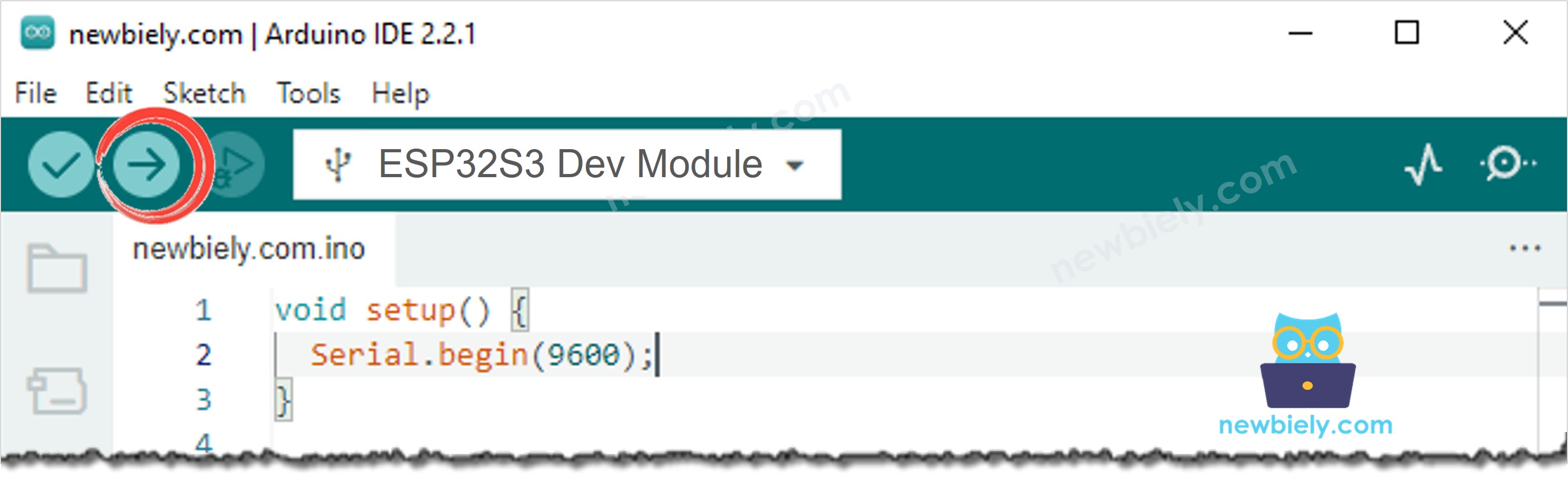
- Upload the code by clicking the Upload button. Wait for "Done uploading" at the bottom of the IDE.
- Open the Serial Monitor with the icon in the top right corner of the IDE.
- Set the baud rate to 9600 in the Serial Monitor.
- Check the output. You should see a new line every second:
- Tip: If you miss the "ready" line, press the RESET button on the board. The sketch starts again from the beginning.
※ NOTE THAT:
If the upload works but the Serial Monitor stays empty, go to Tools USB CDC On Boot, select Enabled, and upload the code again.
Congratulations! Your ESP32 S3 Uno is now set up and running your code.
Next Steps
Your setup is finished, so you can start real projects. These tutorials are a good path for a beginner:
- ESP32 S3 Uno - Blink LED: control your first external LED.
- ESP32 S3 Uno - Button: read a push button.
- ESP32 S3 Uno - Potentiometer: read an analog value with the 12-bit ADC.
- ESP32 S3 Uno - Servo Motor: move a servo with the ESP32Servo library.
- ESP32 S3 Uno - Web Server: control the board from a web page over WiFi.
Video Tutorial
Watch the video below to see this ESP32 S3 Uno project step by step.
FAQ
Which board should I select in the Arduino IDE for the ESP32 S3 Uno?
Select ESP32S3 Dev Module under Tools > Board > esp32. This option comes with the "esp32 by Espressif Systems" package. Do not select an Arduino UNO board, because the ESP32 S3 Uno uses a different chip.
Can I use the UNO R4 board package for the ESP32 S3 Uno?
No. The UNO R4 package is made for the Renesas chip on the Arduino UNO R4. The ESP32 S3 Uno has an Espressif chip, so it needs the "esp32 by Espressif Systems" package. The two boards share the Uno shape, but not the software.
Do I need to install a USB driver for the ESP32 S3 Uno?
Often you do not, because most computers detect the board on their own. If no COM port shows up, your computer may need a driver for the USB-to-serial chip on the board, such as CP210x or CH340. Install the right driver and plug the board in again.
Is the ESP32 S3 Uno 5V or 3.3V?
The ESP32 S3 Uno uses 3.3V logic. The board has a 5V pin to power modules, but its GPIO pins are not 5V tolerant. A 5V signal going into a pin needs a level shifter or a voltage divider.
Can I use Arduino Uno shields on the ESP32 S3 Uno?
Many shields fit, because the headers are in the same places. A shield works well if it runs at 3.3V and does not use A4/A5 for I2C. If a shield sends 5V signals to the pins, or needs I2C on A4/A5, it will not work without changes.
What if my project needs more pins than the Uno headers give?
The ESP32 S3 Uno has two extra rows of holes with more GPIOs. GPIO15 and GPIO16 can do I/O, PWM and analog. GPIO45 and GPIO35 to GPIO42 can do I/O and PWM. GPIO47 and GPIO48 are output only with PWM. Solder pin headers to these holes and write the GPIO number in your code. Use GPIO15/16 for analog sensors, and GPIO35 to GPIO42 for buttons and other digital inputs. Be careful with two groups of pins. First, GPIO47 and GPIO48 may run at 1.8V instead of 3.3V on some modules (especially ones with "V" in the name, like R8V or R16V), so 3.3V devices can be damaged or act strangely. Second, GPIO0, GPIO3 (D6), GPIO45 and GPIO46 (D9) are boot strapping pins, and a wrong connection can stop the board from booting or uploading code. Use the other extra pins first.
Why is the esp32 package download so big?
The package includes the compiler, upload tools and libraries for many ESP32 chips, not only the ESP32 S3 Uno chip. This is why it can take several minutes to install. You only need to install it once.
Troubleshooting
| Problem | Possible Cause | Solution |
|---|---|---|
| "esp32 by Espressif Systems" is not found in Boards Manager | The board index is not loaded | Add the Espressif URL in File > Preferences > Additional Boards Manager URLs and search again |
| ESP32S3 Dev Module is not in the board list | The esp32 package did not finish installing | Open Boards Manager and install or reinstall "esp32 by Espressif Systems" |
| No COM port shows up | Missing USB driver or charge-only cable | Install the CP210x or CH340 driver and use a USB Type-C data cable |
| Upload fails with "Failed to connect" | The board is not in upload mode | Hold the BOOT button, press and release RESET, then release BOOT and upload again |
| Upload works but the Serial Monitor is empty | Wrong baud rate or USB CDC is off | Set the Serial Monitor to 9600, or enable Tools > USB CDC On Boot and upload again |
| Serial Monitor shows strange characters | Baud rate does not match the code | Set the Serial Monitor baud rate to 9600 |
| Board does not boot after wiring a part | A part pulls a boot strapping pin (D6 or D9) | Remove the wire from D6 or D9, upload, then connect it again |
| Permission denied on the port (Linux) | User is not in the dialout group | Run the dialout command from Step 1, then log out and log in again |