
ESP32 S3 UNO - Joystick - Servo Motor
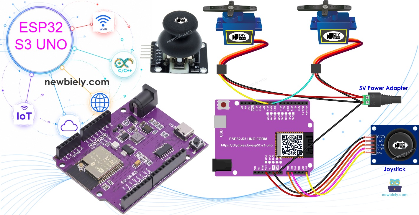
This ESP32 S3 Uno joystick servo motor tutorial shows you how to move two servo motors, or a pan-tilt kit, with a thumb joystick. You wire the joystick and two servos to the ESP32 S3 Uno form board, then write Arduino code that turns each joystick axis into a servo angle. Push the stick, and the pan-tilt head follows your hand.
In this tutorial, you will:
- Wire a joystick and two servo motors to the ESP32 S3 Uno
- Read the joystick X and Y values with analogRead()
- Map the joystick position to a servo angle with map()
- Use joystick directions as commands to step a pan-tilt kit
- Reset the servos to the center with the joystick button
How the joystick drives the servos
A joystick holds two potentiometers set at right angles to each other. One measures the X-axis and one measures the Y-axis. Their signals come out on the VRX and VRY pins. In this project, the X value moves servo motor #1 and the Y value moves servo motor #2. Mount the two servos in a pan-tilt kit, and the head can turn left and right and tilt up and down.
Use case 1 - the servos copy the joystick position
The servo angles follow the joystick's horizontal (X) and vertical (Y) position. When you let go of the stick, it springs back to the middle, and both servos go back to their center position too.
Use case 2 - the joystick sends direction commands
Here the joystick works like a set of arrow keys:
- Push left, and servo motor #1 turns clockwise.
- Push right, and servo motor #1 turns counterclockwise.
- Push up, and servo motor #2 turns clockwise.
- Push down, and servo motor #2 turns counterclockwise.
- Let go, and the servos stay where they are.
- Press the joystick button, and both servos go back to the center.
Hardware Preparation
| 1 | × | ESP32 S3 Uno-form Board | |
| 1 | × | USB Cable Type-A to Type-C (for USB-A PC) | |
| 1 | × | USB Cable Type-C to Type-C (for USB-C PC) | |
| 1 | × | Joystick | |
| 2 | × | Servo Motor | |
| 2 | × | Optionally, Pan-tilt kit with servo motor | |
| 1 | × | Jumper Wires |
Or you can buy the following kits:
| 1 | × | DIYables Sensor Kit (18 sensors/displays) |
Additionally, some of these links are for products from our own brand, DIYables .
Buy Note: For controlling multiple servo motors, use the PCA9685 16 Channel PWM Servo Driver Module to save MCU pins and simplify wiring.
Overview of Joystick and Servo Motor
This project joins two parts you may already know. If the joystick or the servo motor is new to you, learn each one on its own first. It makes this project much easier to follow.
The joystick tutorial explains the VRX, VRY and SW pins and the values they give. The servo tutorial explains how the angle is set and how to power the motor.
ESP32 S3 Uno Pinout
The picture below shows the pinout of the ESP32 S3 Uno form board. Use it to find the A0, A1, A5, D9 and D10 headers and their GPIO numbers before you wire the circuit.

Wiring Diagram
The joystick uses three analog headers, and each servo gets its own PWM pin. Follow the picture and the table below.
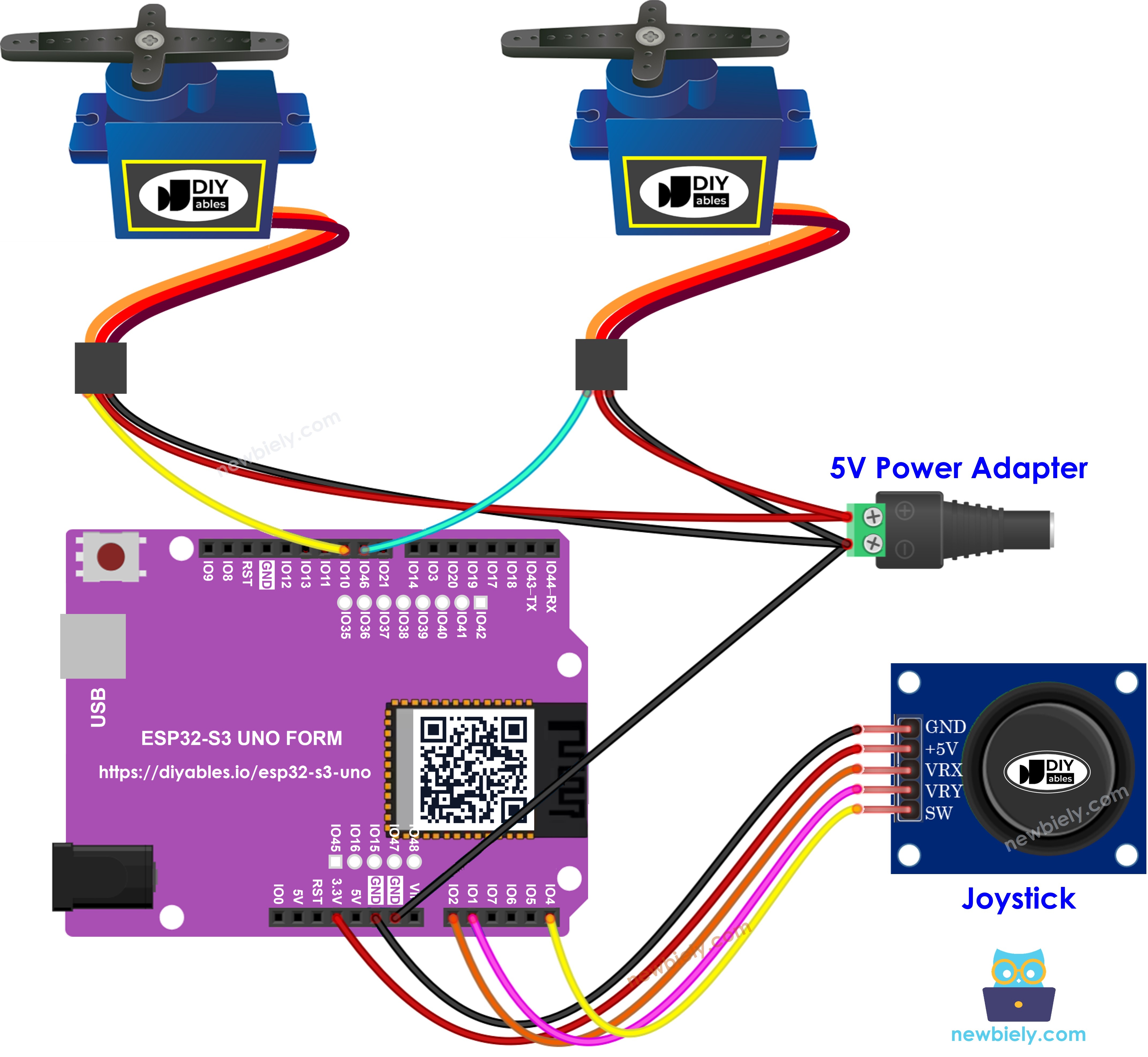
This image is created using Fritzing. Click to enlarge image
| Component Pin | ESP32 S3 Uno Pin |
|---|---|
| Joystick VCC (+5V) | 3.3V |
| Joystick GND | GND |
| Joystick VRX | A0 (GPIO2) |
| Joystick VRY | A1 (GPIO1) |
| Joystick SW | A5 (GPIO4) |
| Servo #1 VCC (red) | 5V |
| Servo #1 GND (brown or black) | GND |
| Servo #1 Signal (orange or yellow) | D9 (GPIO46) |
| Servo #2 VCC (red) | 5V |
| Servo #2 GND (brown or black) | GND |
| Servo #2 Signal (orange or yellow) | D10 (GPIO10) |
WARNING
D9 is GPIO46 on the ESP32 S3 Uno. It is a boot strapping pin, which the chip reads at startup to choose the boot mode. A servo signal wire is usually safe here, but if the board does not boot or upload, unplug the servo #1 signal wire from D9, upload the code, and plug it back in.
WARNING
ESP32 S3 Uno pins are NOT 5V tolerant. Power the joystick from 3.3V, not 5V, so the VRX and VRY outputs never go above 3.3V. The servos can still use 5V for power, because their signal wires only receive the 3.3V signal from the board.
ESP32 S3 Uno Code
There are two sketches below, one for each use case. Both read the joystick on A0 and A1 and drive the servos on D9 and D10. They use ESP32Servo.h instead of Servo.h, because the standard Servo library does not support ESP32 boards.
ESP32 S3 Uno Code - The servo motors rotate according to the movement of the joystick's thumb
This sketch reads both joystick axes, maps each value from 0 to 4095 into an angle from 0° to 180°, and writes it to the matching servo. It also prints the raw values and the angles to the Serial Monitor.
The sketch calls analogSetAttenuation(ADC_11db) in setup(). By default, the ESP32 S3 Uno ADC can only measure a small voltage. With 11 dB attenuation, the analog pins read the full range from 0V up to about 3.3V. Without it, the readings hit 4095 too early and the servos reach 180° before the stick is fully pushed.
Detailed Instructions
- New to the ESP32 S3 Uno? Follow ESP32 S3 Uno - Getting Started first.
- Wire it up as shown in the diagram.
- Connect the board to your computer with a USB Type-C cable.
- Open Arduino IDE, choose the ESP32S3 Dev Module board and the correct COM port.
- Install the servo library. Open the Library Manager, search for ESP32Servo, and install the one by Kevin Harrington.
- Copy the code above and paste it into the Arduino IDE.
- Upload the code. Click the Upload button to send the sketch to the ESP32 S3 Uno.
- Open the Serial Monitor and set the baud rate to 9600.
- Move the joystick in any direction.
- Watch the servos turn, and check the values in the Serial Monitor.
- Tip: The center value of a joystick is rarely exactly 2047. If a servo is a bit off center at rest, that is normal. You can shift the map() range a little to fix it.
ESP32 S3 Uno Code - Use the joystick to command servo motors
This sketch checks the joystick every 100 ms. If the X or Y value passes a threshold, it turns that into a LEFT, RIGHT, UP or DOWN command and moves the servo by one degree. The thresholds (1600 and 3200) are set for the 12-bit ADC range of 0 to 4095. The ezButton library reads the joystick button and puts both servos back at 90°.
Detailed Instructions
- Install the button library. Click the Libraries icon on the left side of the Arduino IDE.
- Search for ezButton, and find the button library by ArduinoGetStarted.com.
- Click Install to add the ezButton library.
- Search for ezButton created by ArduinoGetStarted.com and click the Install button.
- Copy the code above and paste it into the Arduino IDE.
- Upload the code. Click the Upload button to send the sketch to the ESP32 S3 Uno.
- Open the Serial Monitor and set the baud rate to 9600.
- Push the joystick left, right, up or down and hold it.
- Watch the servos move step by step, and check the commands in the Serial Monitor.
- Tip: Hold the stick in one direction to keep the servo moving. Press the joystick button any time to bring the pan-tilt head back to the center.
Code Explanation
Each line of both sketches has a comment that tells you what it does. Read the code from top to bottom with the comments. The flow is simple: set up the servos, the ADC and the button once, then read the joystick, work out the angle, and write it to the servos in a loop.
Video Tutorial
Watch the video below to see this ESP32 S3 Uno project step by step.
Function References
These pages explain the functions used in this project in more detail. The Servo functions work the same way with the ESP32Servo library.
FAQ
Can I use the normal Servo library with the ESP32 S3 Uno?
No. The standard Servo.h library does not support ESP32 boards. Install the ESP32Servo library by Kevin Harrington and include ESP32Servo.h. The functions attach(), write() and read() work the same way, so the rest of the code does not change.
Should I power the joystick from 3.3V or 5V?
Use 3.3V. The ESP32 S3 Uno pins are not 5V tolerant. A joystick on 5V can send up to 5V into A0 and A1 and damage the pins. With 3.3V, the full stick range maps to 0 to 4095.
Why does the code call analogSetAttenuation(ADC_11db)?
It sets the ESP32 S3 Uno ADC input range to about 0V to 3.3V, so the full joystick signal maps to 0 to 4095. Without it, the range is smaller and the readings reach 4095 too early. The UNO R4 does not need this line, it is for ESP32 boards only. Keep the joystick output at 3.3V or less.
Why are the command thresholds 1600 and 3200?
The ESP32 S3 Uno ADC is 12-bit, so the joystick gives values from 0 to 4095, with the center near 2047. A value below 1600 means the stick is pushed one way, and a value above 3200 means it is pushed the other way. If your joystick is very sensitive or not sensitive enough, move these numbers closer to or further from the center.
Can I power two servo motors from the ESP32 S3 Uno 5V pin?
Two small servos like the SG90 often work from the 5V pin when the board runs on USB. When both move at once, they can draw enough current to reset the board. If that happens, use an external 5V supply for the servos and connect its GND to the board GND.
What if my project needs more pins than the Uno headers give?
The ESP32 S3 Uno has two extra rows of holes with more GPIOs. GPIO15 and GPIO16 are I/O, PWM and analog. GPIO45 and GPIO35 to GPIO42 are I/O and PWM. GPIO47 and GPIO48 are output only, with PWM. Solder pin headers to use them and write the GPIO number in code. For this project, a second joystick fits GPIO15 and GPIO16, and extra servos fit GPIO35 to GPIO42. Be careful with two things. First, GPIO47 and GPIO48 may run at 1.8V instead of 3.3V on some modules (especially ones with "V" in the name, like R8V or R16V), so 3.3V devices can be damaged or act strangely. Second, GPIO0, GPIO3 (D6), GPIO45 and GPIO46 (D9) are boot strapping pins, and a wrong connection can stop the board from booting or uploading code. Use the other extra pins first.
Troubleshooting
| Problem | Possible Cause | Solution |
|---|---|---|
| No COM port in Arduino IDE | Missing USB driver or board not in upload mode | Install the CP210x or CH340 driver, try another cable, or hold BOOT while pressing RESET |
| Upload fails or board does not boot | Servo #1 signal on D9 (GPIO46) affects the boot strapping pin | Unplug the servo #1 signal wire during upload, then plug it back in |
| Compile error about Servo.h or ezButton.h | Library not installed or wrong servo library | Install ESP32Servo by Kevin Harrington and ezButton by ArduinoGetStarted.com |
| Servos reach the end before the stick is fully pushed | ADC attenuation not set or joystick on 5V | Keep analogSetAttenuation(ADC_11db) in setup() and power the joystick from 3.3V |
| Servo does not move at all | Signal wire on the wrong pin or no common ground | Check the signal wires are on D9 and D10 and the servo GND is tied to the board GND |
| Board resets when both servos move | Servos draw too much current from the board | Use an external 5V supply for the servos and share GND with the board |
| Servo moves on its own in the command sketch | Joystick center value is past a threshold | Print the raw X and Y values and move the thresholds further from the center |
| Button press does nothing | SW wire not on A5 or loose | Check the SW wire goes to A5 (GPIO4) and that button.loop() runs at the start of loop() |