
ESP32 S3 UNO - Ultrasonic Sensor - OLED
This ESP32 S3 Uno ultrasonic sensor OLED tutorial shows you how to build a small digital distance meter. You will wire an HC-SR04 ultrasonic sensor and an SSD1306 OLED display to the ESP32 S3 Uno form board. The board measures how far an object is and shows the distance in centimeters, right in the middle of the OLED screen.
In this tutorial, you will:
- Wire an HC-SR04 ultrasonic sensor and an I2C OLED display to the ESP32 S3 Uno
- Protect the 3.3V pin from the 5V ECHO signal
- Install the Adafruit SSD1306 and GFX libraries in Arduino IDE
- Measure distance with pulseIn() and display it on the OLED
- Center text horizontally and vertically on the OLED screen
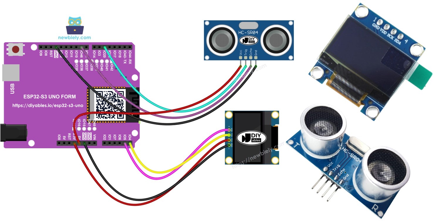
Hardware Preparation
Or you can buy the following kits:
| 1 | × | DIYables Sensor Kit (18 sensors/displays) |
Additionally, some of these links are for products from our own brand, DIYables .
Buy Note: If you want a bigger OLED display, use the 2.42 inch OLED Display 128x64 .
Overview of OLED and Ultrasonic Sensor
This project joins a sensor and a display. The ultrasonic sensor measures the distance, and the OLED shows the number so you do not need a computer to read it. If one of these parts is new to you, learn it alone first. The tutorials below cover the pinout, how each part works, and how to program it.
How the project works
The HC-SR04 sends a short burst of sound that you cannot hear. The sound hits an object and comes back. The sensor keeps its ECHO pin HIGH for as long as the trip takes. The ESP32 S3 Uno measures this time and turns it into centimeters.
The OLED display talks to the board over I2C, using only two signal wires (SDA and SCL). The code writes the distance as text and places it in the center of the screen.
ESP32 S3 Uno Pinout
The image below shows the pinout of the ESP32 S3 Uno form board. Use it to find the D5, D9, SDA and SCL header pins and their GPIO numbers when you wire the circuit.

Wiring Diagram
The sensor's TRIG pin goes to D5 and its ECHO pin goes to D9. The OLED display uses the SDA and SCL header pins.
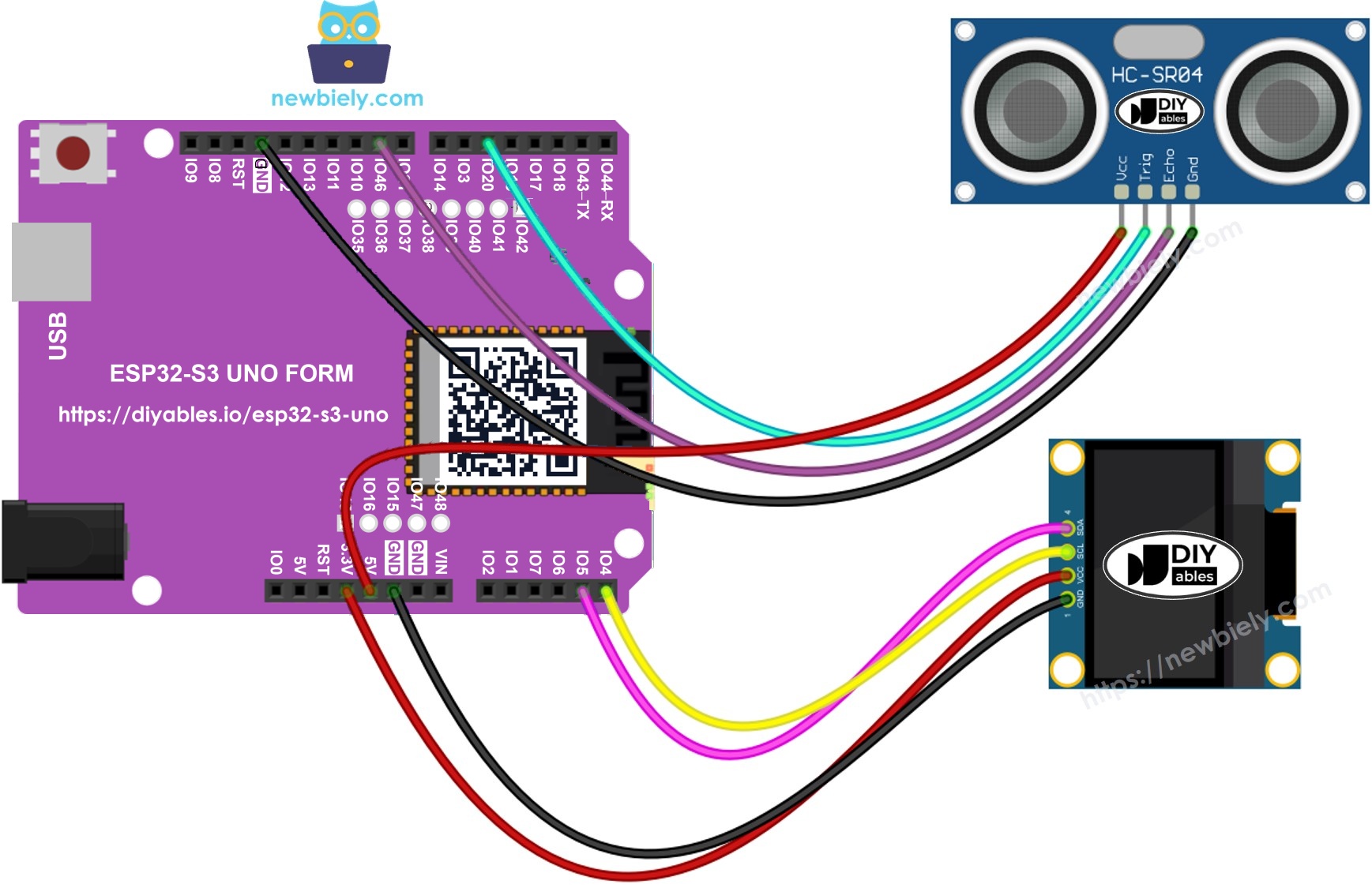
This image is created using Fritzing. Click to enlarge image
| Component Pin | ESP32 S3 Uno Pin |
|---|---|
| Ultrasonic Sensor VCC | 5V |
| Ultrasonic Sensor TRIG | D5 (GPIO20) |
| Ultrasonic Sensor ECHO (through level converter) | D9 (GPIO46) |
| Ultrasonic Sensor GND | GND |
| OLED VCC | 3.3V |
| OLED GND | GND |
| OLED SDA | SDA (GPIO8) |
| OLED SCL | SCL (GPIO9) |
WARNING
The HC-SR04 runs on 5V, so its ECHO pin gives a 5V signal. The ESP32 S3 Uno pins are NOT 5V tolerant. Put a 5V to 3.3V level converter on the ECHO wire, or use a voltage divider (for example 1 kΩ from ECHO to D9, and 2 kΩ from D9 to GND). You can also use a 3.3V version of the sensor. The TRIG wire needs no change, because a 3.3V pulse is enough to trigger the sensor.
WARNING
Pin D9 is GPIO46 on the ESP32 S3 Uno. It is a boot strapping pin, so the board reads its level at startup. The ECHO signal is LOW when the sensor is idle, so it usually causes no problem. But if the board does not boot or upload, remove the ECHO wire from D9 for a moment, upload the code, then put the wire back.
※ NOTE THAT:
On the ESP32 S3 Uno, A4 and A5 are NOT I2C pins. Always connect the OLED to the SDA (GPIO8) and SCL (GPIO9) header pins.
ESP32 S3 Uno Code - Ultrasonic Sensor - OLED
The sketch sends a 10 microsecond pulse to the TRIG pin and measures how long the ECHO pin stays HIGH. It turns that time into centimeters, prints it to the Serial Monitor, and shows it with two decimal places in the center of the OLED.
Detailed Instructions
- New to the ESP32 S3 Uno? Follow ESP32 S3 Uno - Getting Started first.
- Wire it up as shown in the diagram, with the level converter on the ECHO wire.
- Connect the board to your computer with a USB Type-C cable.
- Open Arduino IDE, choose the ESP32S3 Dev Module board and the correct COM port.
- Open the Library Manager by clicking the Libraries icon on the left side of the Arduino IDE.
- Search for "SSD1306" and find the SSD1306 library by Adafruit.
- Click Install to add the library.
- Search for Adafruit SSD1306 created by Adafruit and click the Install button.
- Install the dependencies. The IDE asks for extra libraries. Click the Install All button.
- Copy the code above and paste it into the Arduino IDE.
- Upload the code by clicking the Upload button.
- Wave your hand in front of the sensor, closer and then farther.
- Check the result on the OLED screen and in the Serial Monitor at 9600 baud.
- Tip: if you use the 128x32 OLED, change SCREEN_HEIGHT to 32 so the text stays in the center.
※ NOTE THAT:
The code puts the text in the middle of the OLED, both across and down. To learn how this works, read the guide How to vertical/horizontal center on OLED.
Video Tutorial
Watch the video below to see this ESP32 S3 Uno project step by step.
FAQ
Why does the code use 20 and 46 instead of 5 and 9?
The board has Uno header labels, but the code uses GPIO numbers. Header D5 is GPIO20 and D9 is GPIO46. So TRIG_PIN is 20 and ECHO_PIN is 46.
Can I connect the OLED to A4 and A5 like on the UNO R4?
No. On the ESP32 S3 Uno, A4 and A5 are only analog pins. The I2C bus is on the SDA (GPIO8) and SCL (GPIO9) header pins, and Wire.begin() uses them by default.
Can I connect the HC-SR04 ECHO pin straight to the ESP32 S3 Uno?
It is not safe. The ESP32 S3 Uno pins work at 3.3V and are not 5V tolerant, but the HC-SR04 gives 5V on ECHO. Use a level converter or a 1 kΩ / 2 kΩ voltage divider on the ECHO wire.
The OLED stays black. What is the OLED I2C address?
Most SSD1306 modules use address 0x3C, which the code uses. Some use 0x3D. Run an I2C scanner sketch to find the real address, then change it in oled.begin().
What if my project needs more pins than the Uno headers give?
The ESP32 S3 Uno has two extra rows of holes with more GPIOs: GPIO15 and GPIO16 (I/O, PWM, analog), GPIO45 and GPIO35 to GPIO42 (I/O, PWM), and GPIO47/GPIO48 (output only, PWM). Solder pin headers to them and write the GPIO number in code. For a second ultrasonic sensor, use GPIO35 to GPIO42 for TRIG and ECHO, and never GPIO47/GPIO48 for ECHO because they are output only. Be careful with two things. First, GPIO47/GPIO48 may run at 1.8V instead of 3.3V on some modules (especially ones with "V" in the name, like R8V or R16V), so 3.3V devices can be damaged or act strangely. Second, GPIO0, GPIO3 (D6), GPIO45 and GPIO46 (D9) are boot strapping pins, and a wrong connection can stop the board from booting or uploading code. Use the other extra pins first.
Does this code work the same as on the UNO R4?
Almost. The Adafruit SSD1306 library, pulseIn() and delayMicroseconds() work the same way on the ESP32 S3 Uno. The pin numbers change, the code sets the TRIG and ECHO pin modes with pinMode(), and you need a level converter because the board uses 3.3V logic.
Troubleshooting
| Problem | Possible Cause | Solution |
|---|---|---|
| No COM port in Arduino IDE | USB driver missing or bad cable | Install the CP210x or CH340 driver, try a data USB cable, or hold BOOT while pressing RESET |
| OLED shows nothing | Wrong I2C pins or wrong address | Wire SDA to GPIO8 and SCL to GPIO9 (not A4/A5) and try address 0x3D |
| Serial Monitor shows SSD1306 allocation failed | OLED not found on the I2C bus | Check the OLED power and I2C wires, then press RESET |
| Distance is always 0 cm | No echo received or ECHO wire not on D9 | Check the ECHO wire and the level converter, and make sure the sensor VCC is on 5V |
| Distance values jump around | Noise or soft object in front of the sensor | Point the sensor at a flat hard surface and filter the readings |
| Text is not centered on a 128x32 OLED | SCREEN_HEIGHT is still 64 | Set SCREEN_HEIGHT to 32 in the code |
| Upload fails or board does not start | The ECHO wire on D9 (GPIO46) affects the boot strapping pin | Remove the wire from D9, upload the code, then reconnect it |
| Missing library error when compiling | Adafruit SSD1306 or GFX library not installed | Install both libraries from the Library Manager |