
ESP32 S3 UNO - Joystick
This ESP32 S3 Uno joystick tutorial shows you how to connect a thumb joystick to the ESP32 S3 Uno form board and read it with Arduino code. You get the X and Y position of the analog joystick plus the state of its push button, and you learn to turn these numbers into clear direction commands.
In this tutorial, you will:
- Learn how a two-axis joystick works and what its five pins do
- Wire a joystick to the ESP32 S3 Uno analog and digital pins
- Read the X and Y values with analogRead()
- Read the joystick button with the ezButton library
- Convert joystick values into LEFT, RIGHT, UP and DOWN commands
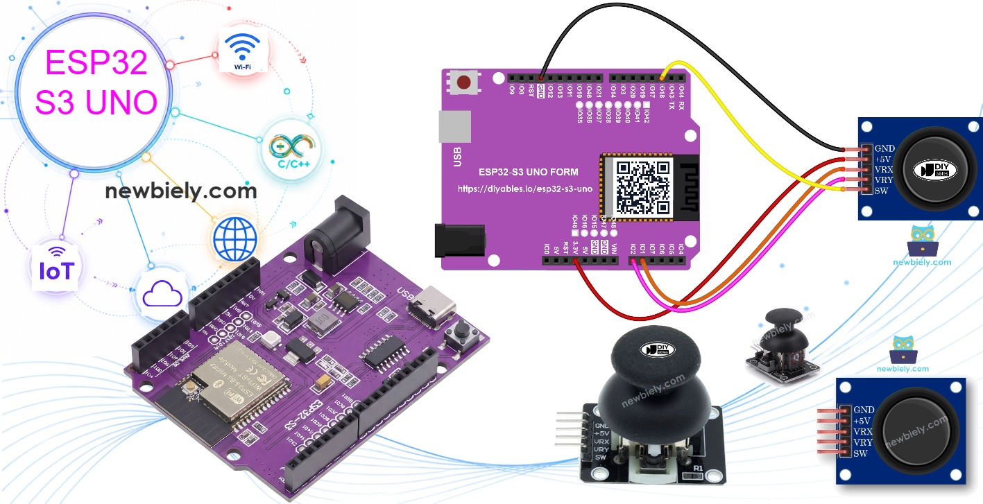
Hardware Preparation
| 1 | × | ESP32 S3 Uno-form Board | |
| 1 | × | USB Cable Type-A to Type-C (for USB-A PC) | |
| 1 | × | USB Cable Type-C to Type-C (for USB-C PC) | |
| 1 | × | Joystick | |
| 1 | × | Jumper Wires |
Or you can buy the following kits:
| 1 | × | DIYables Sensor Kit (18 sensors/displays) |
Additionally, some of these links are for products from our own brand, DIYables .
Overview of Joystick
A joystick gives your project a natural way to steer things. Once you know what it sends to the board, you can use it to drive a robot, move a camera, or play a game.
You have probably seen joysticks on game controllers, toy remotes, and even on the control panels of big machines like excavators.
Inside, a joystick has two potentiometers set at right angles and one push button. It gives you three outputs. The first is an analog value for the horizontal position (the X axis). The second is an analog value for the vertical position (the Y axis). The third is the digital state of the button, HIGH or LOW. On the ESP32 S3 Uno, each analog value is a number from 0 to 4095.
Together, the two analog values form a 2-D coordinate. When you let go of the stick, it springs back to the center, so both values sit near the middle of the range. A simple test sketch (shown later) helps you find which direction is left, right, up and down. Some projects use all three outputs, and some use only one or two.
Pinout
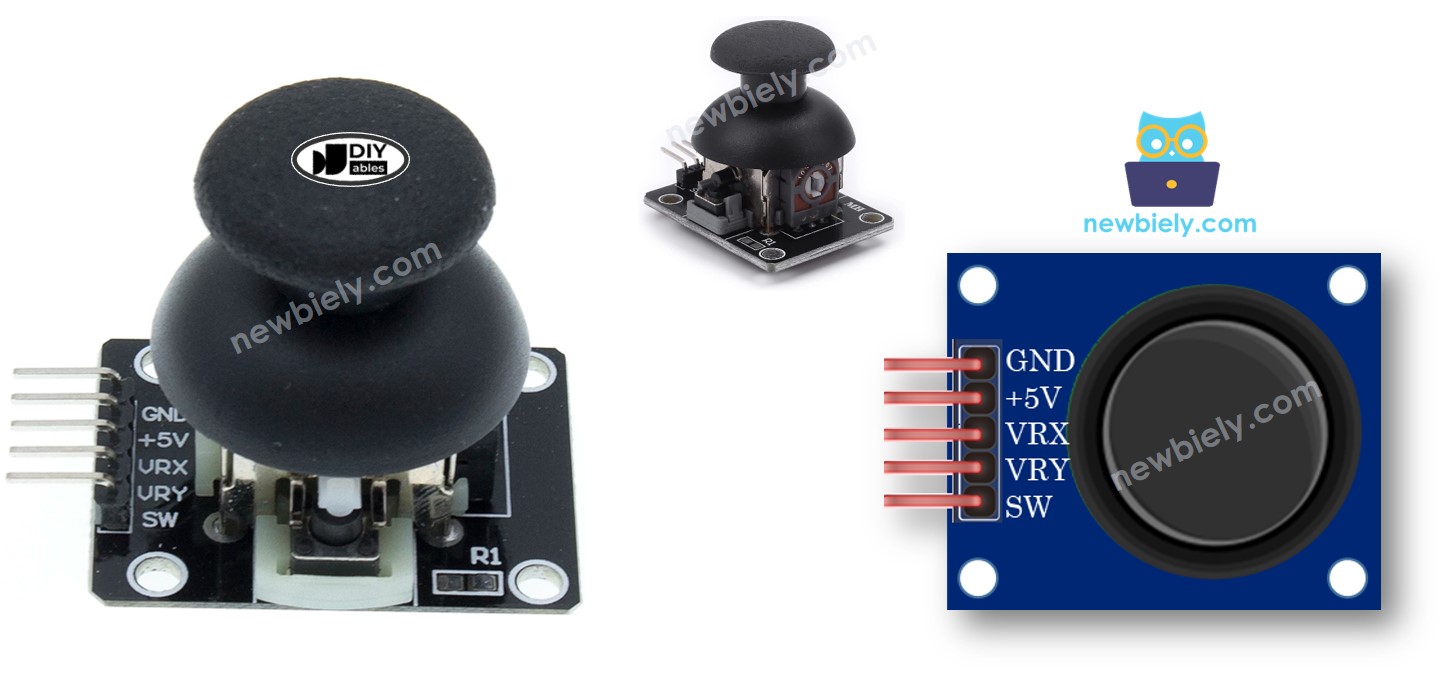
The joystick module has five pins. Two are for power, two carry the axis signals, and one comes from the button.
GND pin
Connect it to GND (0V).
VCC pin
Connect it to the power supply. With the ESP32 S3 Uno, use the 3.3V pin, so the outputs never go above 3.3V.
VRX pin
This pin gives an analog voltage for the horizontal position (X coordinate).
VRY pin
This pin gives an analog voltage for the vertical position (Y coordinate).
SW pin
This pin comes from the push button inside the joystick. The button is normally open. With a pull-up resistor, the pin reads HIGH when the button is free and LOW when you press it.
How It Works
Each axis of the joystick is just a potentiometer. Moving the stick changes a voltage, and the ESP32 S3 Uno measures that voltage.
Left and right
When you push the stick left or right, the voltage on the VRX pin changes. All the way left, it drops to 0V. All the way right, it rises to VCC (3.3V). The ESP32 S3 Uno turns this voltage into a number from 0 to 4095, so 0V reads as 0 and 3.3V reads as about 4095.
Up and down
The VRY pin works the same way. Pushing the stick up lowers the voltage toward 0V, and pushing it down raises it toward 3.3V. The board reads it as a number from 0 to 4095 too.
Diagonal moves
If you move the stick in any other direction, both VRX and VRY change at the same time. Each one shows how far the stick moved along its own axis.
Pressing the stick
When you press down on the stick, it closes the button inside. With a pull-up resistor on the SW pin, the voltage drops from 3.3V to 0V while you hold it. The board reads HIGH when the button is free and LOW when it is pressed.
In short, the two axes give numbers from 0 to 4095, and the button gives HIGH or LOW.
ESP32 S3 Uno Pinout
The image below shows the pinout of the ESP32 S3 Uno form board. Use it to find the A0, A1 and D2 headers and their GPIO numbers before you wire the joystick.

Wiring Diagram
Connect the two axis pins to the A1 and A0 headers, the button pin to D2, and power the joystick from 3.3V.
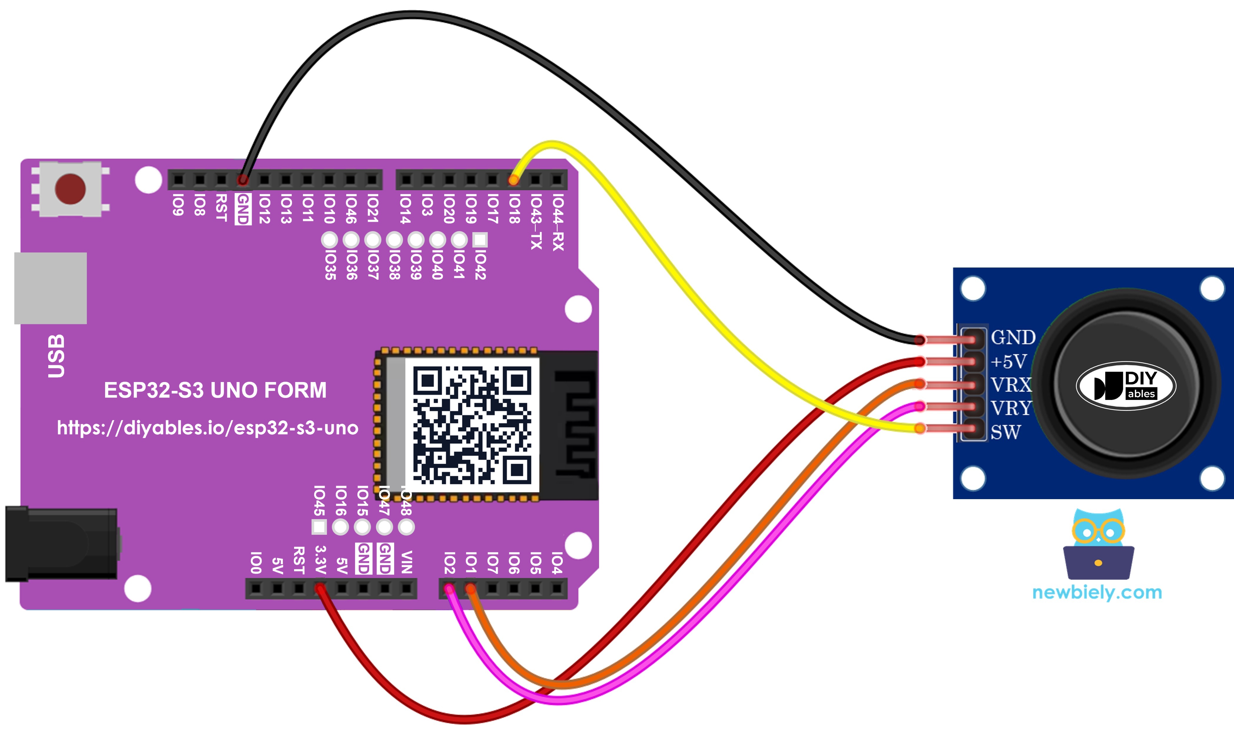
This image is created using Fritzing. Click to enlarge image
| Joystick Pin | ESP32 S3 Uno Pin |
|---|---|
| GND | GND |
| VCC | 3.3V |
| VRX | A1 (GPIO1) |
| VRY | A0 (GPIO2) |
| SW | D2 (GPIO18) |
WARNING
The ESP32 S3 Uno pins are NOT 5V tolerant. If you power the joystick from 5V, the VRX and VRY pins can reach 5V and damage the analog inputs. Always connect the joystick VCC pin to 3.3V.
How To Program For Joystick
A joystick has two parts in code. The analog part gives the X and Y axes, and the digital part is the push button.
- Read the X and Y axes with analogRead(). The A1 header is GPIO1 and the A0 header is GPIO2, so you pass those numbers.
- Treat the push button like any other button. The ezButton library is the easiest way. It turns on the internal pull-up resistor and handles debouncing for you. You can learn more in the ESP32 S3 Uno - Button tutorial.
Raw axis numbers are often not what your project needs. The examples below show how to turn them into something more useful.
ESP32 S3 Uno Code
This section gives you three ready-to-run sketches. Each one builds on the one before, so start with the first.
Example 1
Reads the analog X and Y values from the joystick.
Example 2
Reads the analog values and the state of the joystick button.
Example 3
Turns the analog values into commands: MOVE_LEFT, MOVE_RIGHT, MOVE_UP and MOVE_DOWN.
Example 4
Turns the analog values into angles to drive two servo motors, like a pan-tilt camera. This one has its own tutorial (see below).
Reads analog values from joystick
This sketch reads both axes every 200 ms and prints them to the Serial Monitor. It is the best way to learn which way your joystick is turned on the breadboard.
The line analogSetAttenuation(ADC_11db) in setup() is important. By default, the ESP32 S3 Uno ADC can only measure a small voltage. With 11 dB attenuation, the analog pins read the full range, from 0V up to about 3.3V. Without it, the readings hit 4095 too early and the joystick values look wrong.
Detailed Instructions
- New to the ESP32 S3 Uno? Follow ESP32 S3 Uno - Getting Started first.
- Wire it up as shown in the diagram.
- Connect the board to your computer with a USB Type-C cable.
- Open Arduino IDE, choose the ESP32S3 Dev Module board and the correct COM port.
- Copy the code above and paste it into Arduino IDE.
- Upload the code by clicking the Upload button.
- Move the stick all the way to the edge, then turn it in a full circle (clockwise or counter-clockwise).
- Check the Serial Monitor and watch the values change.
- Tip: while you turn the stick, note where X reads 0. That position is left, and the opposite side is right. Where Y reads 0 is up, and the opposite side is down.
Reads analog values and reads the button state from a joystick
This sketch adds the push button. It prints the X and Y values with the button state, and prints a message each time you press or release the stick.
Detailed Instructions
- Open the Libraries panel by clicking the Libraries icon on the left side of Arduino IDE.
- Search for “ezButton” and find the button library by ArduinoGetStarted.com.
- Install it by clicking the Install button.
- Search for ezButton created by ArduinoGetStarted.com and click the Install button.
- Copy the code and paste it into Arduino IDE.
- Upload the code to the ESP32 S3 Uno.
- Move the stick left, right, up and down.
- Press down on the top of the stick.
- Check the Serial Monitor.
- Tip: the button reads 1 when it is free and 0 when it is pressed, because the library uses the internal pull-up resistor.
Converts analog value to MOVE LEFT/RIGHT/UP/DOWN commands
This sketch compares each axis with two thresholds and prints a command when the stick moves far enough. The thresholds (1600 and 3200) are set for the 12-bit ADC, so the center area around 2048 gives no command.
Detailed Instructions
- Copy the code above and paste it into Arduino IDE.
- Upload the code to the ESP32 S3 Uno.
- Move the stick left, right, up, down, or in any other direction.
- Check the Serial Monitor.
- Tip: if the commands trigger too easily, move the thresholds further from the center (for example 1200 and 3600).
※ NOTE THAT:
At any moment, you may get no command, one command, or two commands together (for example, UP and LEFT when you push the stick diagonally).
Converts analog values to angles to control two servo motors
Mapping the two axes to angles lets you aim two servo motors, like a pan-tilt camera mount. You can find the full guide in the ESP32 S3 Uno - Joystick controls Servo Motor tutorial.
Video Tutorial
Watch the video below to see this ESP32 S3 Uno project step by step.
Function References
FAQ
Should I power the joystick from 3.3V or 5V on the ESP32 S3 Uno?
Use 3.3V. The joystick outputs a voltage between 0V and its VCC, and the ESP32 S3 Uno pins are not 5V tolerant. At 3.3V the stick still works fully, and the values cover 0 to 4095.
Why does my joystick read 0 to 4095 instead of 0 to 1023?
The ESP32 S3 Uno has a 12-bit ADC, so analog readings go from 0 to 4095. A board like the UNO R4 uses a 10-bit range (0 to 1023) by default. If you copy old code, scale its thresholds by about 4.
Why does the code call analogSetAttenuation(ADC_11db)?
It sets the ESP32 S3 Uno ADC input range to about 0 to 3.3V, so the full joystick swing maps to 0 to 4095. Without it, the range is smaller and the readings reach 4095 long before the stick hits the edge. The UNO R4 does not need this line, because it is ESP32-only. Keep the joystick output at 3.3V or less.
Why is the center value not exactly 2048?
The two potentiometers are not perfect, and the ESP32 S3 Uno ADC is not perfectly linear. The resting value is often a little off, such as 1950 or 2100, and it can jitter a bit. Use a dead zone (like the 1600 to 3200 band in the command example) so small changes do not trigger moves.
Which pins can I use for the joystick?
The X and Y pins need analog inputs, such as A0 to A5 or D2 to D7. The SW pin can go to any normal digital pin. Avoid D6 (GPIO3) and D9 (GPIO46), because they are boot strapping pins.
What if my project needs more pins than the Uno headers give?
The ESP32 S3 Uno has two extra rows of holes with more GPIOs. GPIO15 and GPIO16 support I/O, PWM and analog, GPIO45 and GPIO35 to GPIO42 support I/O and PWM, and GPIO47/GPIO48 are output only with PWM. Solder pin headers to use them and write the GPIO number in code. For a second joystick, use GPIO15 and GPIO16 for the axes and a pin like GPIO35 for its button. Do not use GPIO47/GPIO48 for inputs. Be careful with two things. First, GPIO47/GPIO48 may run at 1.8V instead of 3.3V on some modules (especially ones with "V" in the name, like R8V or R16V), so 3.3V devices can be damaged or act strangely. Second, GPIO0, GPIO3 (D6), GPIO45 and GPIO46 (D9) are boot strapping pins, and a wrong connection can stop the board from booting or uploading code. Use the other extra pins first.
Troubleshooting
| Problem | Possible Cause | Solution |
|---|---|---|
| No COM port appears in Arduino IDE | Missing USB driver or the board is not in upload mode | Install the CP210x or CH340 driver, try another cable, or hold BOOT while you press RESET |
| X and Y values stay at 0 or jump around | Loose wire or the joystick has no power | Check the GND and VCC wires and make sure VRX and VRY go to A1 and A0 |
| Values hit 4095 before the stick reaches the edge | ADC attenuation is not set | Keep analogSetAttenuation(ADC_11db) in setup() |
| Analog pin damaged or readings wrong after wiring | Joystick powered from 5V | Move the joystick VCC wire to the 3.3V pin |
| Button always reads 1 or never changes | SW wire is on the wrong pin or the code uses another pin | Wire SW to D2 (GPIO18) and keep SW_PIN at 18 |
| ezButton.h not found when compiling | Library is not installed | Install the ezButton library from the Library Manager |
| Commands appear when the stick is not touched | Center value is outside the dead zone | Widen the thresholds, for example 1200 and 3600 |
| Serial Monitor shows strange characters | Baud rate does not match | Set the Serial Monitor to 9600 baud |