
ESP32 S3 UNO RS232
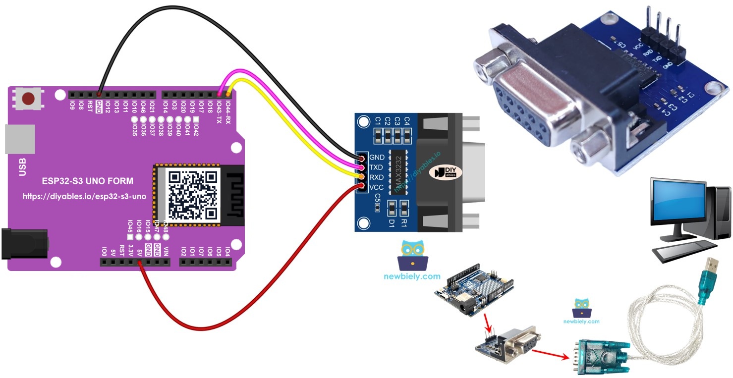
This ESP32 S3 Uno RS232 tutorial shows you how to connect a TTL to RS232 module and exchange data with a serial device over a DB9 cable. The ESP32 S3 Uno form board talks TTL UART, and the MAX3232-based module turns it into real RS-232 signals for PCs, PLCs and industrial gear. You will build a simple echo test that sends back every character it gets.
In this tutorial, you will:
- Wire a TTL to RS232 module to the ESP32 S3 Uno
- Receive RS232 data from a serial device through the module
- Send RS232 data back to the serial device
- Use a hardware UART on D0/D1 or on other pins (instead of SoftwareSerial)
Hardware Preparation
Or you can buy the following kits:
| 1 | × | DIYables Sensor Kit (18 sensors/displays) |
Additionally, some of these links are for products from our own brand, DIYables .
Overview of TTL to RS232 Module
Every time your sketch calls print(), read() or write() on a serial port, the ESP32 S3 Uno moves bits on its TX and RX pins. Those bits are TTL level (0V and 3.3V), and they only work over short wires. For long cables you need a stronger signal standard such as RS232, RS485 or RS422.
The TTL to RS232 module does this job for you. It converts the board's TTL signals into RS232 voltage levels, and it converts incoming RS232 signals back to TTL so the board can read them.
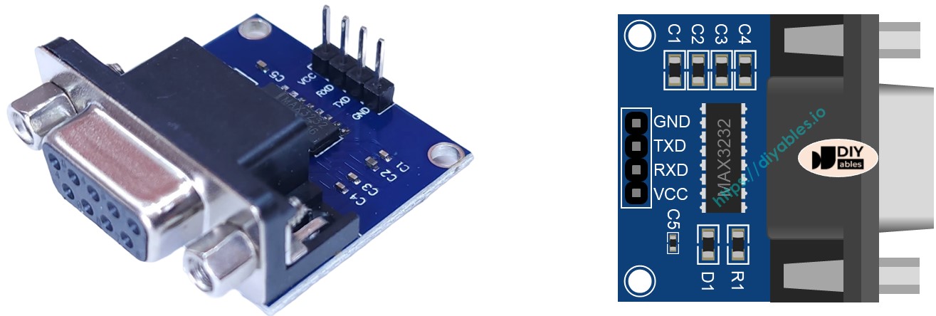
Pinout
The module has two sides. One side talks to the ESP32 S3 Uno, and the other side talks to your serial device.
TTL side (4 pins, goes to the ESP32 S3 Uno)
| Pin | Function |
|---|---|
| VCC | Power input. Connect it to 3.3V or 5V. Use 3.3V with the ESP32 S3 Uno |
| GND | Ground. Connect it to GND (0V) |
| RXD | Data pin. Connect it to an RX pin of the ESP32 S3 Uno |
| TXD | Data pin. Connect it to a TX pin of the ESP32 S3 Uno |
RS232 side
This side is a DB9 female D-Sub connector. Plug your serial device (or an RS232 to USB cable) into it.
WARNING
The ESP32 S3 Uno pins are 3.3V logic and are NOT 5V tolerant. Power the module from the 3.3V pin, so its TTL output also stays at 3.3V. If you power it from 5V, its TXD pin can send 5V into the board and damage it.
ESP32 S3 Uno Pinout
The image below shows the pinout of the ESP32 S3 Uno form board. Use it to find the Uno header pins (D0, D1, D6, D7…) and their GPIO numbers while you wire the module.

Wiring Diagram
You can wire the module in two ways. The first way uses the D0/D1 serial pins. The second way uses D7/D6 with a second hardware UART.
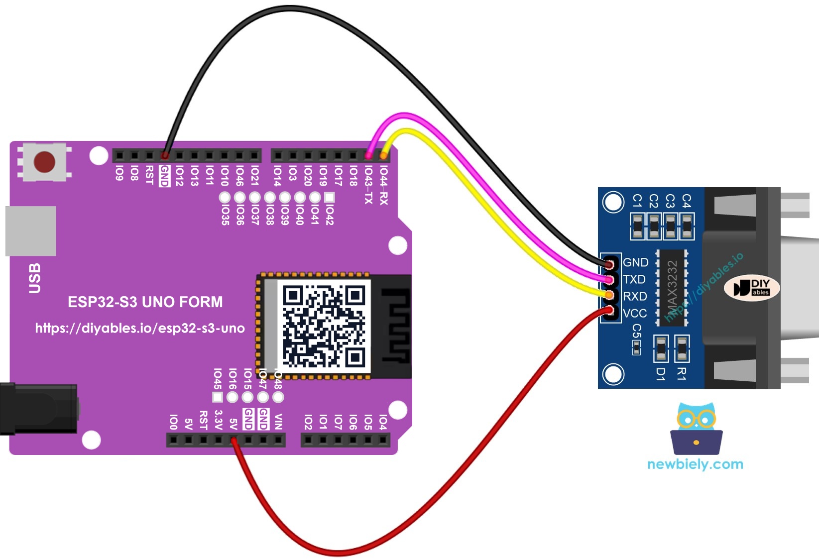
Option 1 - D0/D1 pins (Serial1)
This image is created using Fritzing. Click to enlarge image
| RS232 Module Pin | ESP32 S3 Uno Pin |
|---|---|
| VCC | 3.3V |
| GND | GND |
| RXD | D0 (GPIO44) |
| TXD | D1 (GPIO43) |
WARNING
D0 (GPIO44) and D1 (GPIO43) are the UART0 pins. On the ESP32 S3 Uno they are also connected to the USB-serial chip that uploads code and runs the Serial Monitor. Unplug the module's wires from D0/D1 while you upload a sketch, then plug them back in. Do not use the Serial Monitor at the same time as the module on these pins. If you can, use Option 2 instead.
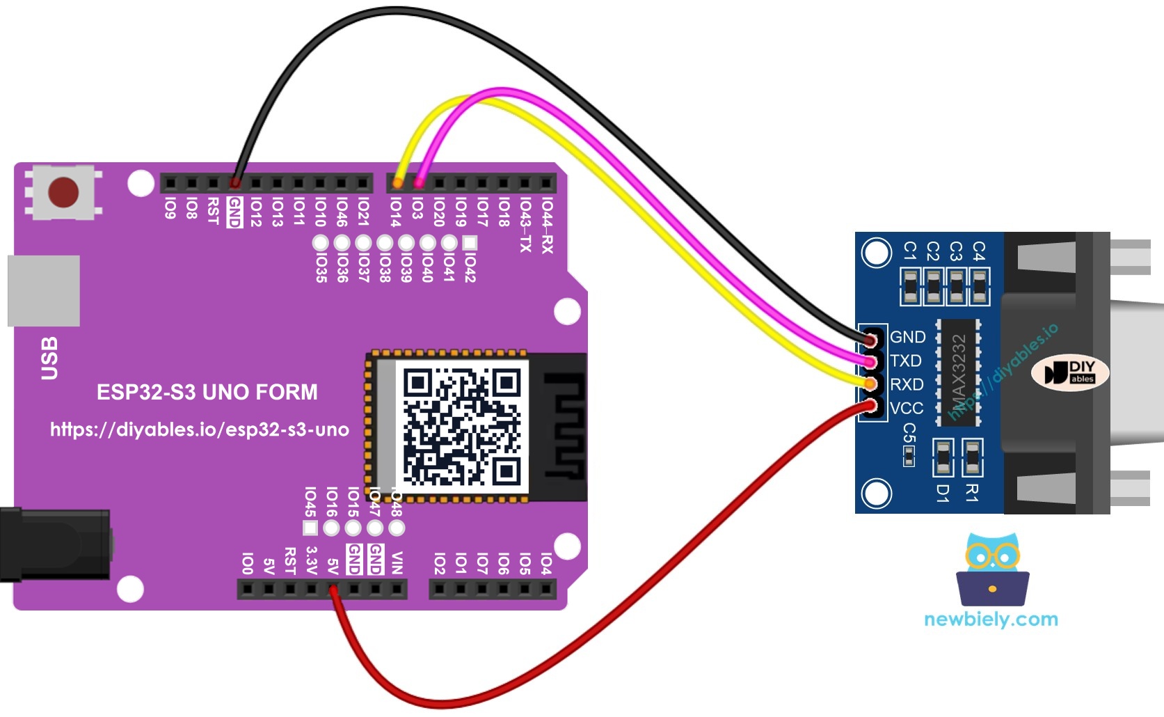
Option 2 - D7/D6 pins (Serial2)
This image is created using Fritzing. Click to enlarge image
| RS232 Module Pin | ESP32 S3 Uno Pin |
|---|---|
| VCC | 3.3V |
| GND | GND |
| RXD | D7 (GPIO14) |
| TXD | D6 (GPIO3) |
WARNING
D6 is GPIO3, a boot strapping pin. The board reads it at startup to choose the boot mode. In most cases the module does not cause a problem, but if the board does not boot or upload while the module is connected, unplug the D6 wire, press RESET, and plug it back in after the board starts.
How To Program ESP32 S3 Uno to use the RS232 module
The ESP32 S3 Uno has three hardware UARTs, and you can route them to almost any GPIO. That is why you do not need the SoftwareSerial library here. You just tell Serial1 or Serial2 which pins to use.
Start a serial port
For Option 1 (D0/D1), start Serial1 on GPIO44 (RX) and GPIO43 (TX):
For Option 2 (D7/D6), start Serial2 on GPIO14 (RX) and GPIO3 (TX). This replaces the SoftwareSerial object you would use on other boards:
Read and send data
The functions below are written for Serial, but they work the same on Serial1 and Serial2. To read data that comes in from RS232, use:
To send data out through RS232, use:
You can find more functions in the Serial reference.
ESP32 S3 Uno Code for Hardware Serial
This sketch uses Option 1 wiring. It starts Serial1 on D0/D1 at 9600 baud, waits for a character from the RS232 device, and sends the same character straight back.
ESP32 S3 Uno Code for Software Serial
This sketch uses Option 2 wiring. The ESP32 S3 Uno has no SoftwareSerial library, so the code uses the spare hardware port Serial2 on D7/D6 instead. It does the same echo job, and it is more reliable than a software serial port.
Testing
First upload one of the sketches. Then send data from your PC and check that it comes back.
- New to the ESP32 S3 Uno? Follow ESP32 S3 Uno - Getting Started first.
- Wire it up as shown in the diagram for the option you picked.
- Connect the board to your computer with a USB Type-C cable.
- Open Arduino IDE, choose the ESP32S3 Dev Module board and the correct COM port.
- Copy the code for your wiring option and paste it into Arduino IDE.
- Upload the code with the Upload button. If you use Option 1, unplug the D0/D1 wires first and plug them back in after the upload.
Now test the link between your PC and the ESP32 S3 Uno over RS232:
- Connect the RS232 side of the module to your PC with the RS232 to USB cable, as shown below.
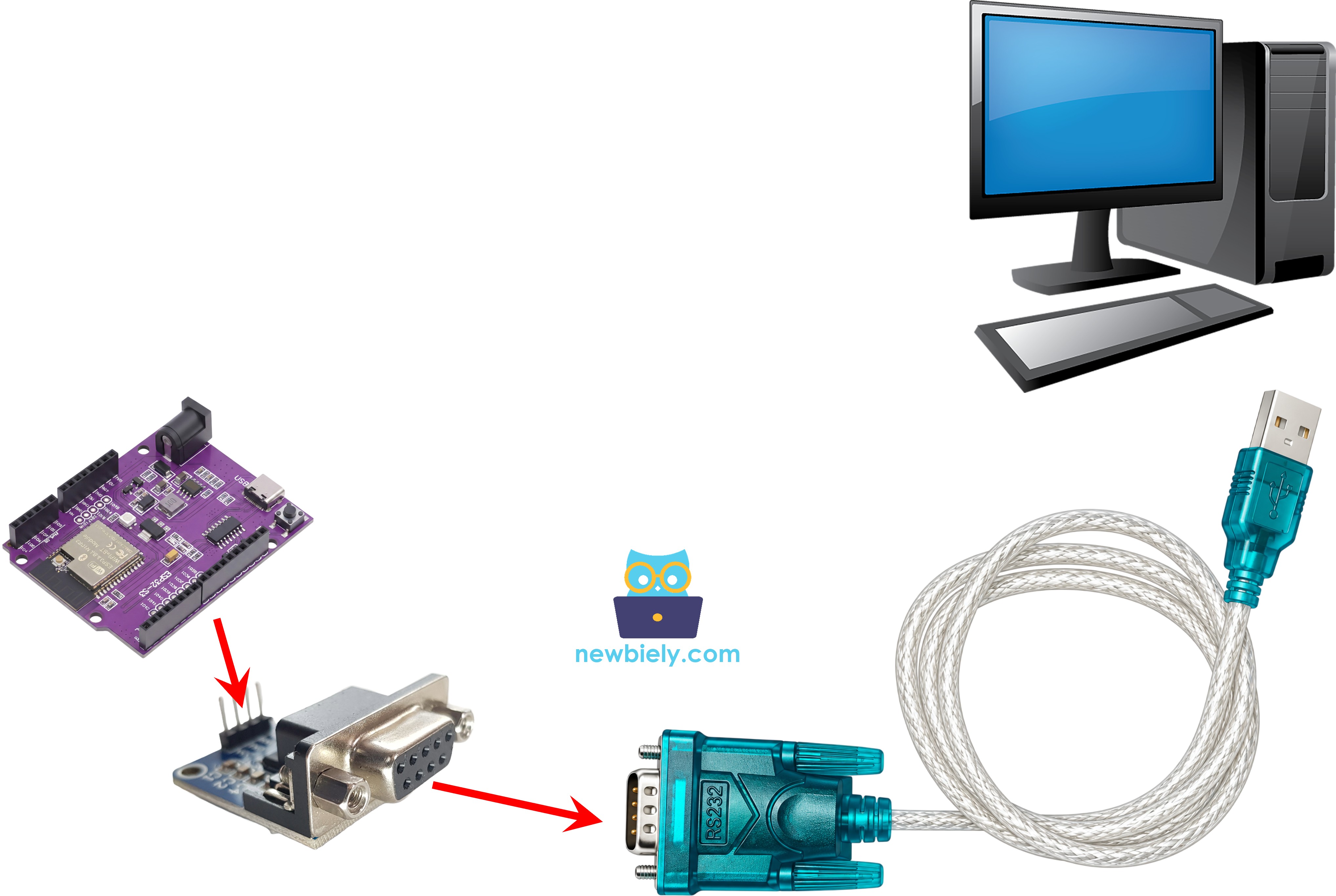
- Open the terminal on the COM port of the RS232 to USB cable (not the board's USB port). Set it to 9600 baud, 8 data bits, no parity, 1 stop bit.
- Type some text in the terminal to send it to the ESP32 S3 Uno.
- Check the result - every character you type shows up again in the terminal, because the board echoes it back.
- Tip: If you see nothing, turn off "local echo" in the terminal first, so you only see what the board sends back. Then swap the RXD and TXD wires if it still does not work.
Video Tutorial
Watch the video below to see this ESP32 S3 Uno project step by step.
FAQ
Can I use SoftwareSerial on the ESP32 S3 Uno?
No, the classic SoftwareSerial library is made for AVR boards like the UNO. The ESP32 S3 Uno has three hardware UARTs, and you can map Serial1 and Serial2 to almost any GPIO with begin(baud, SERIAL_8N1, RX, TX). Hardware UARTs are faster and more reliable anyway.
Should I power the RS232 module from 3.3V or 5V on the ESP32 S3 Uno?
Use 3.3V. MAX3232-based modules work from 3.3V to 5V, and at 3.3V their TTL pins stay at a safe level. The ESP32 S3 Uno pins are not 5V tolerant, so a module powered from 5V can push 5V into the RX pin.
Why does the upload fail when the module is wired to D0/D1?
On the ESP32 S3 Uno, D0 (GPIO44) and D1 (GPIO43) are shared with the USB-serial chip. The module's signal fights with the upload data. Unplug the D0/D1 wires while uploading, or use the D7/D6 option with Serial2.
Can I connect the ESP32 S3 Uno TX/RX pins directly to a PC's RS232 port?
No. Real RS232 uses about +/-3V to +/-15V, and negative voltages will destroy the board's pins. Always put a TTL to RS232 module (like MAX3232) between the board and the DB9 port.
What baud rate should I use?
Both sides must use the same settings. The code uses 9600 baud, 8 data bits, no parity, 1 stop bit (SERIAL_8N1). If your device uses another speed, change the number in begin() and in the terminal program.
What if my project needs more pins than the Uno headers give?
The ESP32 S3 Uno has two extra rows of holes with more GPIOs. GPIO15 and GPIO16 are I/O, PWM and analog. GPIO45 and GPIO35 to GPIO42 are I/O and PWM. GPIO47 and GPIO48 are output only, with PWM. Solder pin headers to use them and write the GPIO number in code. For a second RS232 module, GPIO35 to GPIO42 are a good choice for RX and TX (RX needs an input pin, so never use GPIO47/48 for RX). Watch out for two things. First, GPIO47 and GPIO48 may run at 1.8V instead of 3.3V on some modules (especially ones with "V" in the name, like R8V or R16V), so 3.3V devices can be damaged or act strangely. Second, GPIO0, GPIO3 (D6), GPIO45 and GPIO46 (D9) are boot strapping pins, and a wrong connection can stop the board from booting or uploading code. Use the other extra pins first.
Troubleshooting
| Problem | Possible Cause | Solution |
|---|---|---|
| No COM port in Arduino IDE | USB driver missing or board not in download mode | Install the CP210x or CH340 driver. Hold BOOT, press RESET, then release BOOT and try again |
| Upload fails with Option 1 wiring | Module is wired to D0/D1 which share the USB-serial lines | Unplug the D0/D1 wires during upload, then reconnect them |
| Board does not boot with Option 2 wiring | D6 (GPIO3) is a boot strapping pin | Unplug the D6 wire, press RESET, then reconnect it after the board starts |
| Nothing comes back in the terminal | RXD and TXD swapped or GND not connected | Check the wiring table, swap RXD and TXD if needed, and connect GND |
| Strange characters in the terminal | Baud rate or frame settings do not match | Set the terminal to 9600 baud, 8 data bits, no parity, 1 stop bit |
| Terminal shows each character twice | Local echo is turned on in the terminal | Turn off local echo in Tera Term or PuTTY |
| Board gets hot or stops working | Module powered from 5V and sends 5V into an RX pin | Power the module from 3.3V |
| Terminal opens but no data at all | Wrong COM port selected | Pick the COM port of the RS232 to USB cable, not the board's USB port |