
DIYables Web Apps Web Digital Pins
Overview
This ESP32 S3 Uno digital pins tutorial shows you how to control and monitor the Uno header pins of the ESP32 S3 Uno form board from a web page. You switch outputs ON and OFF with one click, and you see input states change live in your browser. The DIYables ESP32 WebApps library builds the web GPIO control page and the WebSocket link for you, so your phone or PC becomes a remote control panel.
In this tutorial, you will:
- Install the DIYables ESP32 WebApps library in the Arduino IDE
- Control digital pins from a web browser on your phone or PC
- Monitor input pins in real time over WebSocket
- Map the web pin numbers to the real GPIO numbers of the board
- Use bulk buttons (All ON, All OFF, Toggle All) to test many outputs at once
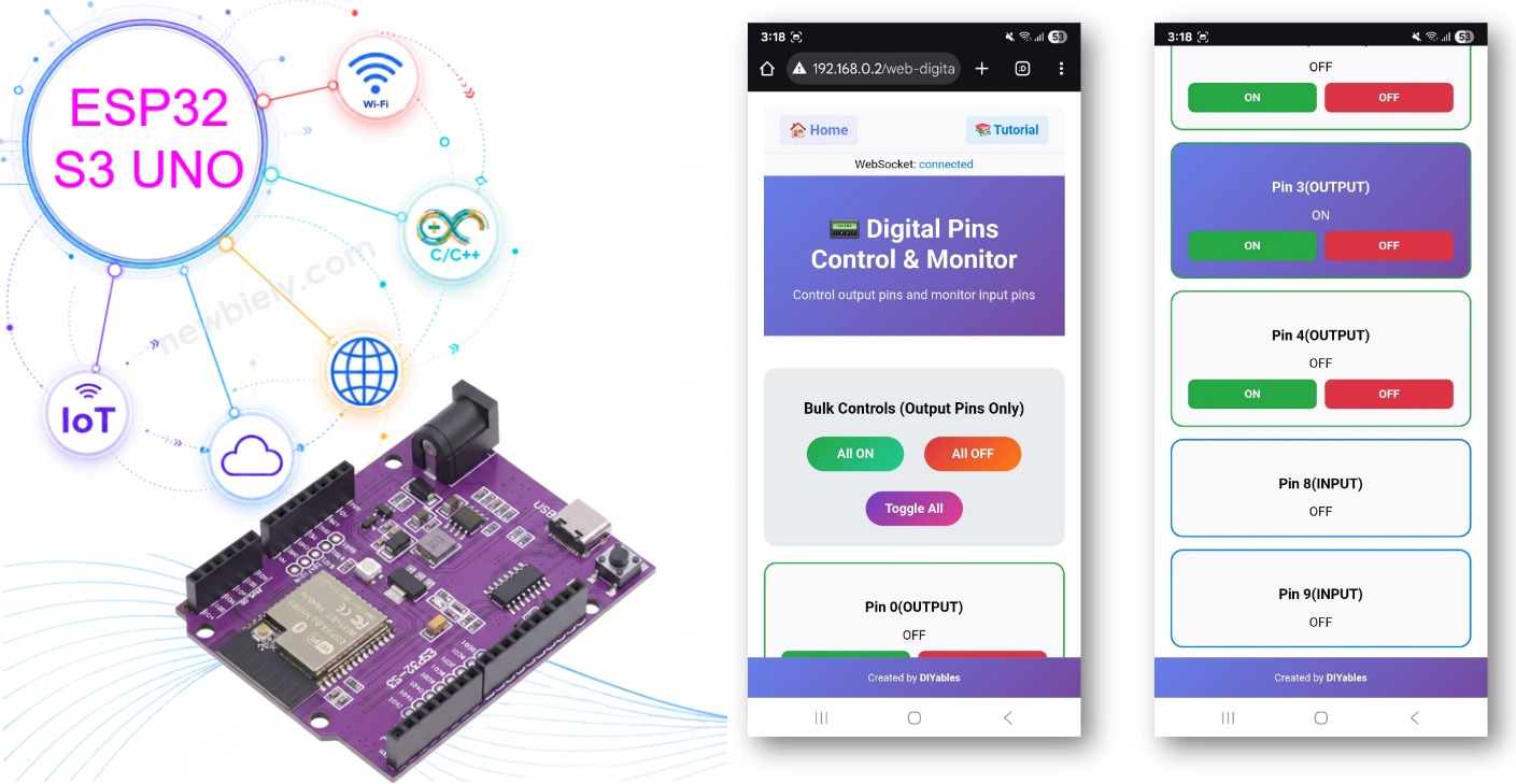
A step-by-step video is at the bottom of this page.
Features
The Web Digital Pins app turns a browser tab into a small control panel. Here is what it gives you.
One button per pin
Every pin you enable gets its own button on the page. You control each pin by its Uno label (D2, D3 … D13), separately from the others.
Live status
Buttons change color with the pin state: green for ON and red for OFF. Input pins update by themselves when the signal changes.
Bulk control
Three buttons, All ON, All OFF and Toggle All, act on every output pin at the same time.
Input or output from the page
You can switch a pin between Input and Output mode directly in the web interface.
Works on every screen
The page fits desktop, tablet and phone screens. It talks to the board over WebSocket, so updates appear without a page refresh.
Hardware Preparation
| 1 | × | ESP32 S3 Uno-form Board | |
| 1 | × | USB Cable Type-A to Type-C (for USB-A PC) | |
| 1 | × | USB Cable Type-C to Type-C (for USB-C PC) |
Or you can buy the following kits:
| 1 | × | DIYables Sensor Kit (18 sensors/displays) |
Additionally, some of these links are for products from our own brand, DIYables .
Setup Instructions
Detailed Instructions
The example sketch needs no extra parts to start. Connect a few LEDs later if you want to see the outputs change. Follow these steps in order:
- New to the ESP32 S3 Uno? Follow ESP32 S3 Uno - Getting Started first.
- Wire it up (optional): connect an LED with a 220Ω resistor to D13 (GPIO12), because this board has no built-in LED on D13.
- Connect the board to your computer with a USB Type-C cable.
- Open Arduino IDE, choose the ESP32S3 Dev Module board and the correct COM port.
- Open the Library Manager by clicking the Libraries icon on the left bar of the Arduino IDE.
- Search for the library: type "DIYables ESP32 WebApps" and find the DIYables ESP32 WebApps Library by DIYables.
- Install it by clicking the Install button.
- Search for DIYables ESP32 WebApps created by DIYables and click the Install button.
- Install the dependencies: the IDE asks about other required libraries. Click Install All.
- Get the code: in the Arduino IDE, go to File Examples DIYables ESP32 WebApps WebDigitalPins, or copy the ESP32 S3 Uno code below into the editor.
The sketch below is made for the ESP32 S3 Uno. The web page always uses pin numbers 0–13, which here mean the Uno header labels D0–D13. A small table, UNO_TO_GPIO, turns each label into the real GPIO number, so digitalWrite() and digitalRead() drive the right pin. D0 and D1 are left disabled, because they carry the Serial Monitor on this board.
- Set your WiFi: change these two lines to your network name and password:
- Upload the code by clicking the Upload button in the Arduino IDE.
- Open the Serial Monitor and set it to 9600 baud. You should see something like this:
- No output? Press the RESET button on the board and watch the Serial Monitor again.
- Open the web page: write down the IP address and type it into the address bar of a browser on your phone or PC, for example http://192.168.0.2. The home page looks like this:
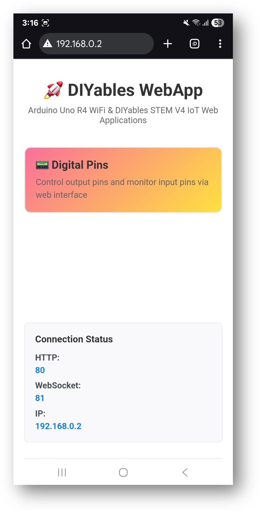
- Open the Web Digital Pins app by clicking its link. You will see this interface:
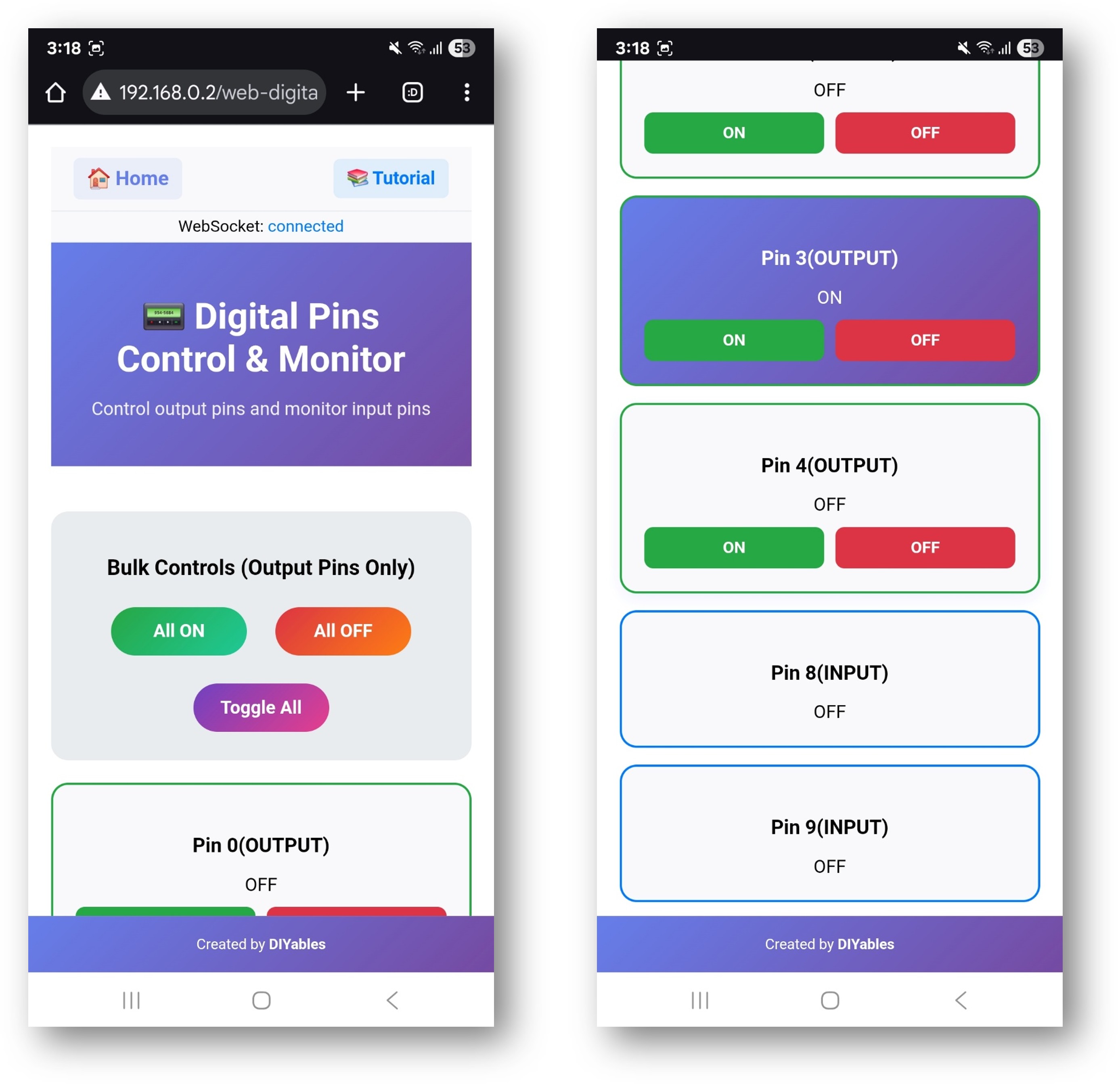
- Go there directly next time: add /web-digital-pins after the IP address, for example http://192.168.0.2/web-digital-pins.
- Tip: click the pin 13 button to switch it ON and OFF. If you wired the external LED to D13 (GPIO12), it lights up and goes dark with each click.
Creative Customization - Adapt the Code to Your Project
Your project decides which pins you need and in which mode. The sketch shows a few ways to pick them. In all of them, the number you pass is the Uno label (2 means D2), and the web page accepts 0 to 13 only.
2. Configure Pin Settings
Choose the method that fits the number of pins you use.
Method 1: Enable Specific Pins
Pick pins one by one. This is the clearest way when you use only a few pins.
Method 2: Enable Pin Ranges
A for loop enables a block of pins in a few lines.
Method 3: Enable All Pins
One call enables every pin from 0 to 13. On the ESP32 S3 Uno, D0 and D1 are the Serial Monitor pins, so disable them again if you still need the Serial Monitor.
4. Upload the Sketch
- Choose the board: Tools → Board → esp32 → ESP32S3 Dev Module
- Choose the port: Tools → Port → [your ESP32 S3 Uno port]
- Click the Upload button
5. Get the IP Address
- Open Tools → Serial Monitor
- Set the baud rate to 9600
- Wait until the ESP32 S3 Uno joins your WiFi
- Note the IP address it prints (for example 192.168.1.100)
6. Access the Digital Pins Interface
In your web browser, open this address:
Example: http://192.168.1.100/web-digital-pins
How to Use
The page is simple, but knowing what each part shows saves you time when you test real hardware.
Pin Control Interface
Each enabled pin appears as a card. The card shows the pin number (the Uno label, 0–13), the current state (ON in green or OFF in red), a button to toggle the state, and the pin type (Input or Output).
Individual Pin Control
- Turn a pin ON: click its button while it shows "OFF"
- Turn a pin OFF: click its button while it shows "ON"
- Watch the state: the buttons update by themselves to show the current state
Bulk Operations
The bulk buttons act on many pins with one click. They only change output pins. Input pins always show the real signal.
All ON
This sets every output pin to HIGH. It is a fast way to check that all connected LEDs or relays work.
All OFF
This sets every output pin to LOW. Use it as a safe "everything off" button.
Toggle All
This flips every output: ON pins go OFF and OFF pins go ON. Click it a few times for a simple blinking effect.
Real-time Monitoring
The page and the board talk over WebSocket, so a change shows up right away. If your code changes a pin and reports it, the page updates too. Several people can open the page at the same time and watch the same ESP32 S3 Uno.
ESP32 S3 Uno Pinout
The pinout diagram below shows the ESP32 S3 Uno form board. Use it to find each Uno header pin (D2, D9, D13…) and its GPIO number before you connect LEDs, relays or switches.

Hardware Connections
The web page only switches pins. What happens next depends on what you connect. Below are common examples, written with the Uno label and the GPIO number. Remember that ESP32 S3 Uno pins use 3.3V logic and are NOT 5V tolerant.
Output Pin Examples
LED Control
Relay Control
Motor Control (via Motor Driver)
WARNING
D6 (GPIO3) and D9 (GPIO46) are boot strapping pins on the ESP32 S3 Uno. The chip reads them at startup to choose its boot mode. If a motor driver or another circuit pulls them to the wrong level during reset, the board may not boot or may fail to upload code. If that happens, unplug the wire from that pin while you upload, or move the signal to a free pin such as D2, D3, D4 or D5.
Input Pin Examples
Switch Input
Use 3.3V for the pull-up resistor, not 5V.
Sensor Input
WARNING
Many relay modules and ultrasonic sensors (like the HC-SR04) run at 5V. A 5V signal going INTO an ESP32 S3 Uno pin, such as the ultrasonic Echo pin, can damage the board. Use a voltage divider (for example 1kΩ and 2kΩ) or a logic level shifter. For relay modules, choose one that accepts a 3.3V input signal.
Code Customization
The library gives you callbacks, so you can add your own logic around each web action. In the snippets below, pin is always the Uno label (0–13), and UNO_TO_GPIO[pin] gives the real GPIO number.
Adding Pin Change Callbacks
The onPinWrite() callback runs every time someone clicks an output button. Add your own actions inside it, like printing a message.
Custom Pin Initialization
The small helper below sets an output by its Uno label and tells the web page about it. The other snippets on this page use it too.
Reading Input Pins
This loop reads every enabled input once per second and sends the value to the page.
Advanced Features
When the basic version works, you can group pins or run patterns from your own code. The page still shows every change.
Pin Groups
Put related pins in arrays, then switch a whole group with one function call.
Pattern Generation
This "running light" turns on one pin at a time, from D2 to D13, every 500 ms.
PWM Control Integration
Every Uno digital pin on the ESP32 S3 Uno supports PWM, so you can mix ON/OFF control with brightness control.
Safety Considerations
A wrong connection can stop the board from booting or even damage a pin. Read these notes before you connect real loads.
Pin Usage Guidelines
D0 and D1 (RX/TX)
On the ESP32 S3 Uno, D0 (GPIO44) and D1 (GPIO43) are the UART0 pins that carry the Serial Monitor and code upload. Avoid them. Using them as outputs stops Serial Monitor messages and can get in the way of uploading.
D13
D13 (GPIO12) is a good pin for your first test, but the ESP32 S3 Uno has no built-in LED on it. Connect an external LED with a 220Ω resistor to see the result.
D6 and D9
D6 (GPIO3) and D9 (GPIO46) are boot strapping pins. They work fine as normal I/O after startup, but a circuit that pulls them to the wrong level during reset can stop the board from booting or uploading.
D2–D5, D7, D8, D10–D12
These are the safest pins for general digital input and output. Use them first in your projects.
Current Limitations
Maximum current per pin
An ESP32 S3 Uno pin can give only a small current. Keep it under about 20mA, and never go above the 40mA absolute limit. Always use a resistor with LEDs, and use a transistor or a relay module for motors, lamps and other big loads. Also watch the total current of all pins together.
Voltage levels
ESP32 S3 Uno pins use 3.3V logic and are NOT 5V tolerant. Make sure every connected device works with 3.3V signals, and use a level shifter or voltage divider for 5V signals.
Common Problems and Debug Tips
Common Issues
1. A pin does not respond
Check that the pin is enabled in the code and that its mode (Input or Output) is right. Then check the wiring and look for short circuits. Remember that the code number 13 means D13 (GPIO12), not GPIO13.
2. The web page does not update
Look at the WebSocket status and refresh the browser page. Make sure your phone or PC is on the same WiFi network, and check the Serial Monitor for error messages.
3. Bulk buttons do nothing
The bulk buttons only change output pins, so make sure your pins are set as outputs. Also check that your power supply can feed all loads at the same time.
4. Input pins show the wrong state
A floating input reads random values. Add a pull-up or pull-down resistor (or use INPUT_PULLUP), keep the signal at 3.3V, keep the wires short, and check the pin mode.
Debug Tips
This function prints the state and mode of every enabled pin. Call it from loop() when something looks wrong.
Project Ideas
A web page with ON/OFF buttons fits many real projects. Here are some ideas to start from.
Home Automation
Switch room lights, move window blinds with a motor driver, turn heating or cooling on and off, or arm a simple security system.
Garden Automation
Start and stop an irrigation pump, switch grow lights, and control fans for temperature and humidity.
Tutorial Control
Power tools on and off through relays, control the tutorial lights and ventilation, and add safety interlocks.
Educational Projects
Show how logic gates work, build a traffic light, make an alarm system, or run remote control experiments in class.
Integration Examples
These two examples mix web control with your own logic. They use the setPinState() helper from above.
Motion-Activated Lighting
A PIR sensor on D3 turns on an LED on D2 for 5 seconds. Most PIR modules (like the HC-SR501) give a 3.3V output, which is safe for the ESP32 S3 Uno.
Temperature-Controlled Fan
A fan (through a relay or transistor) on D4 turns on when the temperature goes above 25°C.
Next Steps
When you are comfortable with Web Digital Pins, try these apps from the same library:
- WebSlider – for PWM and analog-style control
- WebJoystick – for direction control
- WebMonitor – for debugging and monitoring in the browser
- MultipleWebApps – to combine all features on one board
Video Tutorial
Watch the video below to see this ESP32 S3 Uno project step by step.
The code below is the demo version. It enables D8 to D11 as outputs: a buzzer on D8 (GPIO21) beeps at 3000 Hz when you switch pin 8 ON, and D9 (GPIO46), D10 (GPIO10) and D11 (GPIO11) work as normal outputs, for example with LEDs. D9 is a boot strapping pin, so read the warning in the Hardware Connections section if the board does not boot.
Support
If you need more help, read the other DIYables ESP32 WebApps tutorials for the ESP32 S3 Uno on this site. The Arduino and Espressif community forums are also good places to ask.
FAQ
Why does the web page show pin numbers 0–13 and not GPIO numbers?
The Web Digital Pins page only accepts pin numbers from 0 to 13, like a classic Uno. In the ESP32 S3 Uno code, these numbers are the Uno header labels D0–D13. The UNO_TO_GPIO table turns each label into the real GPIO, for example 7 → GPIO14 and 13 → GPIO12. If you call pinMode(), digitalWrite() or digitalRead() yourself, always use the GPIO number.
Why are D0 and D1 disabled in the ESP32 S3 Uno code?
D0 (GPIO44) and D1 (GPIO43) are the UART0 pins that the USB-serial chip uses for the Serial Monitor and for uploading. If you set them as outputs, the Serial Monitor stops working and you cannot see the IP address. On the UNO R4 WiFi these pins are free, which is why the original example enables them.
Where is the built-in LED on pin 13?
The ESP32 S3 Uno has no built-in LED on D13. Connect an external LED with a 220Ω resistor between D13 (GPIO12) and GND to see the pin 13 button work.
Can I control 5V relay modules from the web page?
Yes, if the relay module accepts a 3.3V input signal. Many modules power the coil from 5V but switch with a 3.3V signal. Never feed a 5V signal back into an ESP32 S3 Uno pin, because the pins are NOT 5V tolerant.
Is it safe to use D6 and D9 as web-controlled pins?
They work as normal pins after the board starts. But D6 (GPIO3) and D9 (GPIO46) are boot strapping pins, so a circuit that pulls them to the wrong level during reset can stop the board from booting or uploading. Use D2–D5, D7, D8 and D10–D12 first.
What if my project needs more pins than the Uno headers give?
The ESP32 S3 Uno has two extra rows of holes with more GPIOs: GPIO15 and GPIO16 (I/O, PWM, analog), GPIO45 and GPIO35–GPIO42 (I/O, PWM), and GPIO47/GPIO48 (output only, PWM). Solder pin headers to use them and write the GPIO number in code. The web page still only knows numbers 0–13, so give an unused number a new GPIO in the UNO_TO_GPIO table (for example, put 15 in place of D0's 44). For buttons and other inputs, GPIO15, GPIO16 or GPIO35–GPIO42 are good choices; never use GPIO47/GPIO48 as inputs. Be careful with two things: (1) GPIO47/GPIO48 may run at 1.8V instead of 3.3V on some modules (especially ones with "V" in the name, like R8V or R16V), so 3.3V devices can be damaged or act strangely; (2) GPIO0, GPIO3 (D6), GPIO45 and GPIO46 (D9) are boot strapping pins, and a wrong connection can stop the board from booting or uploading code. Use the other extra pins first.
Troubleshooting
| Problem | Possible Cause | Solution |
|---|---|---|
| No COM port appears in the Arduino IDE | USB driver missing or charge-only cable | Install the CP210x or CH340 driver, use a data USB cable, or hold BOOT while you press RESET |
| Serial Monitor shows nothing or stops | D0 or D1 enabled as an output, or wrong baud rate | Keep D0 and D1 disabled and set the Serial Monitor to 9600 baud |
| Board does not connect to WiFi | Wrong SSID or password, or a 5 GHz network | Check WIFI_SSID and WIFI_PASSWORD and use a 2.4 GHz WiFi network |
| Web page does not open | Phone or PC on another network, or wrong IP address | Join the same WiFi and use the IP address printed in the Serial Monitor |
| Clicking pin 13 shows no light | The board has no built-in LED on D13 | Connect an external LED with a 220Ω resistor to D13 (GPIO12) |
| Wrong pin reacts to a button | digitalWrite() uses the Uno label instead of the GPIO | Use UNO_TO_GPIO[pin] or the GPIO number from the pinout |
| Input pin flickers between ON and OFF | Floating input with no pull-up or pull-down | Add a 10kΩ resistor to 3.3V or GND, or use INPUT_PULLUP |
| Board does not boot or upload after wiring | A circuit pulls D6 (GPIO3) or D9 (GPIO46) at reset | Disconnect that wire during upload or move the signal to another pin |