
ESP32 S3 UNO - Keypad - LCD
This ESP32 S3 Uno keypad LCD tutorial shows you how to read the keys of a 3x4 keypad and print them on a 16x2 LCD I2C display. You will build it on the ESP32 S3 Uno form board with the Arduino IDE. Every key you press appears on the LCD screen, so it is a good base for a password lock or a number input project.
In this tutorial, you will:
- Wire a 3x4 keypad and an LCD I2C display to the ESP32 S3 Uno
- Install the DIYables keypad and LCD I2C libraries
- Read key presses with the getKey() function
- Display each pressed key on the LCD and clear it when the line is full
Hardware Preparation
Or you can buy the following kits:
| 1 | × | DIYables Sensor Kit (18 sensors/displays) |
Additionally, some of these links are for products from our own brand, DIYables .
Buy Note: Most LCD I2C displays available on the market are 5V displays. They may work with this board, but it is unsafe and can damage the board. We strongly recommend using the 3.3V LCD I2C display recommended above.
Overview of Keypad and LCD
This project joins two parts you may already know. The keypad is the input, and the LCD is the output. If one of them is new to you, read its own tutorial first. There you will find the pinout, how the part works and a simple test sketch.
How the two parts work together
The 3x4 keypad has 7 pins: 4 row pins and 3 column pins. The ESP32 S3 Uno scans these pins to find which key is pressed. The LCD I2C needs only two signal wires, SDA and SCL, so the keypad and the LCD share the board without any pin conflict.
ESP32 S3 Uno Pinout
The image below shows the pinout diagram of the ESP32 S3 Uno form board. Use it to find the D3 to D9 pins for the keypad and the SDA and SCL pins for the LCD, with their GPIO numbers.

Wiring Diagram
The keypad goes to the digital pins D3 to D9, and the LCD goes to the I2C header pins. Follow the diagram and the tables below.
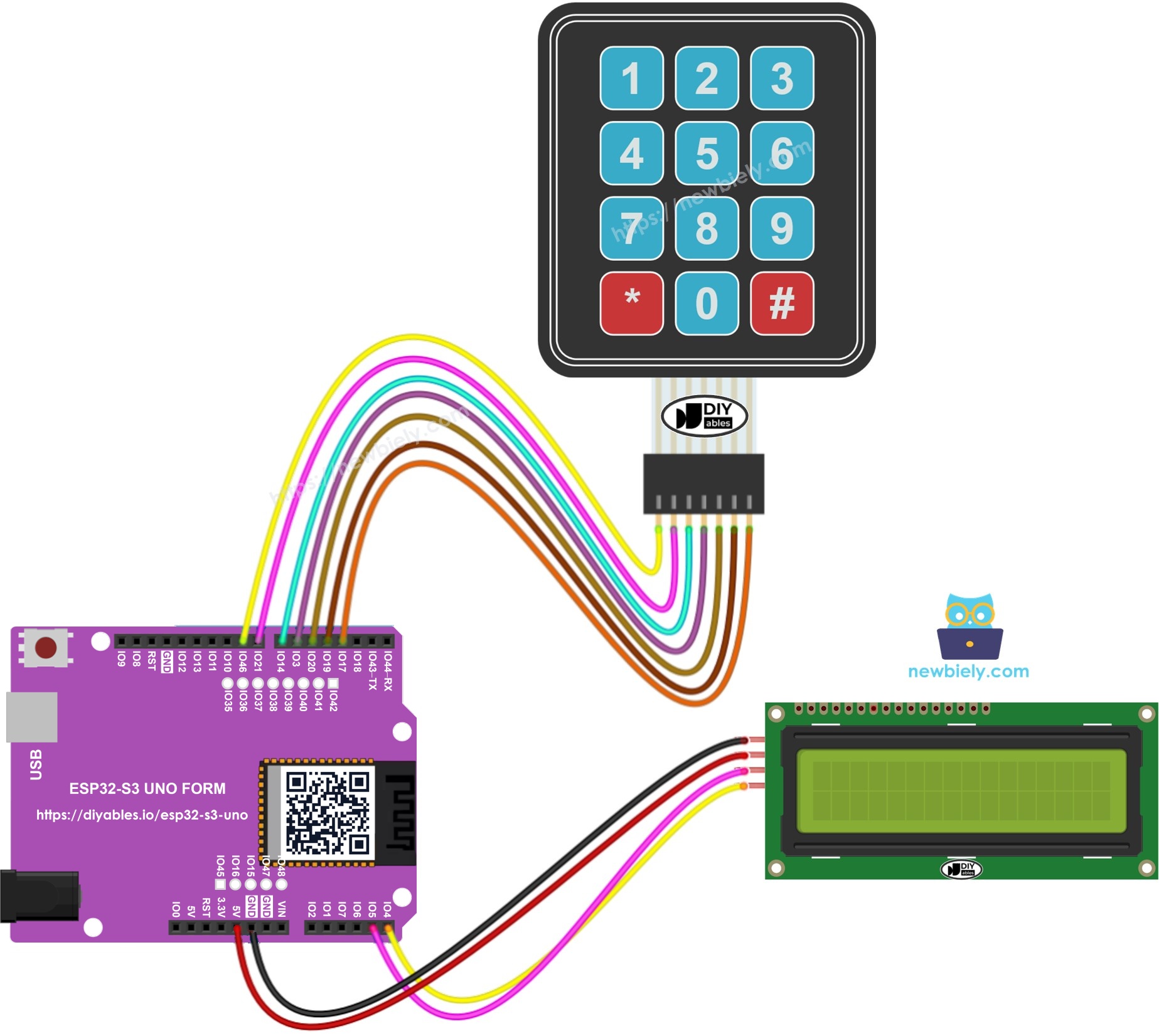
This image is created using Fritzing. Click to enlarge image
Keypad wiring
| Keypad Pin | ESP32 S3 Uno Pin |
|---|---|
| R1 (Row 1) | D9 (GPIO46) |
| R2 (Row 2) | D8 (GPIO21) |
| R3 (Row 3) | D7 (GPIO14) |
| R4 (Row 4) | D6 (GPIO3) |
| C1 (Column 1) | D5 (GPIO20) |
| C2 (Column 2) | D4 (GPIO19) |
| C3 (Column 3) | D3 (GPIO17) |
WARNING
Two keypad rows use boot strapping pins. D9 (GPIO46) and D6 (GPIO3) are read by the ESP32 S3 Uno when it starts. If a key on row 1 or row 4 is held down during power-up or reset, the board may not boot or may fail to upload code. Do not press any key while you reset the board or upload the sketch.
LCD I2C wiring
| LCD I2C Pin | ESP32 S3 Uno Pin |
|---|---|
| GND | GND |
| VCC | 5V |
| SDA | SDA (GPIO8) |
| SCL | SCL (GPIO9) |
On this board, A4 and A5 are only analog pins. The I2C bus is on the SDA (GPIO8) and SCL (GPIO9) header pins, and the LCD library uses them by default.
WARNING
The ESP32 S3 Uno pins work at 3.3V and are NOT 5V tolerant. Many LCD I2C backpacks pull SDA and SCL up to their own VCC, so with 5V power these lines can sit at 5V. To protect the board, put a bidirectional 5V to 3.3V level converter on SDA and SCL, or remove the pull-up resistors on the backpack.
ESP32 S3 Uno Code
The sketch scans the keypad all the time. When you press a key, it prints that character on the first line of the LCD and moves the cursor one step to the right. After 16 characters the line is full, so the code clears the screen and starts again from the left.
※ NOTE THAT:
The I2C address of the LCD can be different from one maker to another. This code uses 0x27, which is the address given by the maker DIYables. If your screen stays blank, run an I2C scanner to find the real address.
Detailed Instructions
- New to the ESP32 S3 Uno? Follow ESP32 S3 Uno - Getting Started first.
- Wire it up as shown in the diagram, with the keypad on D3 to D9 and the LCD on the SDA and SCL header pins.
- Connect the board to your computer with a USB Type-C cable.
- Open Arduino IDE, choose the ESP32S3 Dev Module board and the correct COM port.
- Open the Library Manager by clicking the Libraries icon on the left side of the Arduino IDE.
- Install the keypad library. Type DIYables_Keypad in the search box, find the library by DIYables.io and click Install.
- Search for DIYables_Keypad created by DIYables.io and click the Install button.
- Install the LCD library. Search for DIYables LCD I2C, find the DIYables_LCD_I2C library by DIYables and click Install.
- Search for DIYables LCD I2C created by DIYables.io and click the Install button.
- Copy the code above and paste it into the Arduino IDE.
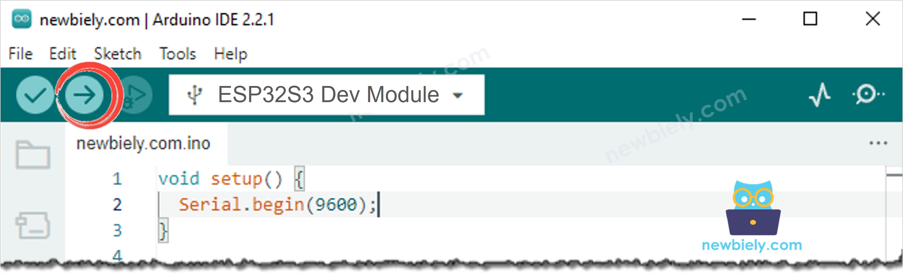
- Upload the code by clicking the Upload button. Do not press any keypad key during the upload.
- Press some keys on the keypad.
- Check the LCD. Each key you press shows up on the first line.
- Tip: If the LCD shows nothing, turn the small blue contrast knob on the back of the LCD, then read the LCD I2C troubleshooting guide.
Code Explanation
The comments inside the code explain each line. In short, the keys array maps every button to a character, and the pin_rows and pin_column arrays tell the library which GPIO pins the keypad uses. In loop(), keypad.getKey() returns the pressed key, or nothing if no key is pressed. The cursorColumn variable keeps track of where the next character goes on the LCD.
Video Tutorial
Watch the video below to see this ESP32 S3 Uno project step by step.
FAQ
Can I power the LCD I2C from the 3.3V pin of the ESP32 S3 Uno?
Most 16x2 LCD I2C modules are made for 5V. At 3.3V the text is often very faint or not visible at all. Power the LCD from 5V and protect SDA and SCL with a level converter, or use an LCD module that is rated for 3.3V.
Why do I wire the LCD to SDA and SCL and not to A4 and A5?
On the ESP32 S3 Uno, A4 (GPIO5) and A5 (GPIO4) are only analog pins. The I2C bus is on the SDA (GPIO8) and SCL (GPIO9) header pins. The LCD library calls Wire.begin(), which uses these two pins by default.
Why does the code use GPIO numbers like 46 and 14 instead of 9 and 7?
The ESP32 S3 Uno code always uses GPIO numbers, not the Uno header labels. The header D9 is GPIO46, D7 is GPIO14, and so on. Look at the wiring table or the pinout image to match each label with its GPIO number.
Can I show the keys on the second line of the LCD too?
Yes. Add a row variable and call lcd.setCursor(cursorColumn, 1) when the first line is full. Clear the LCD only when both lines are full. This gives you 32 characters before the screen resets.
What if my project needs more pins than the Uno headers give?
The ESP32 S3 Uno has two extra rows of holes with more GPIOs: GPIO15 and GPIO16 (I/O, PWM, analog), GPIO45 and GPIO35 to GPIO42 (I/O, PWM), and GPIO47/GPIO48 (output only, PWM). Solder pin headers to use them and write the GPIO number in code. For keypad inputs, GPIO35 to GPIO42 or GPIO15/GPIO16 are good choices. Do not use GPIO47/GPIO48 for the keypad, because they are output only. Two warnings: (1) GPIO47/GPIO48 may run at 1.8V instead of 3.3V on some modules (especially ones with "V" in the name, like R8V or R16V), so 3.3V devices can be damaged or act strangely; (2) GPIO0, GPIO3 (D6), GPIO45 and GPIO46 (D9) are boot strapping pins, and a wrong connection can stop the board from booting or uploading code. Use the other extra pins first.
Troubleshooting
| Problem | Possible Cause | Solution |
|---|---|---|
| No COM port appears in the Arduino IDE | USB driver missing or board not in upload mode | Install the CP210x or CH340 driver, try another USB cable, or hold BOOT while you press RESET |
| Upload fails or the board does not start | A key on row 1 or row 4 is pressed, which pulls D9 (GPIO46) or D6 (GPIO3) at boot | Do not touch the keypad during upload or reset, then try again |
| LCD backlight is on but no text shows | Contrast too low or wrong I2C address | Turn the contrast knob on the back of the LCD and check the address with an I2C scanner |
| LCD stays dark | Loose wires or no 5V power on the LCD | Check that VCC goes to 5V and GND goes to GND, and press each jumper wire firmly |
| LCD does not work at all | SDA and SCL wired to A4 and A5 | Move the wires to the SDA (GPIO8) and SCL (GPIO9) header pins |
| Wrong character appears for a key | Row or column wires swapped | Compare each keypad wire with the wiring table, R1 to D9 and C1 to D5 |
| Some keys do nothing | A row or column wire is loose or broken | Check the wires for that row or column and replace any bad jumper |
| Compile error about a missing header file | Library not installed | Install DIYables_Keypad and DIYables_LCD_I2C from the Library Manager |