
ESP32 S3 UNO - LCD 20x4
This ESP32 S3 Uno LCD 20x4 tutorial shows you how to connect a 20x4 LCD I2C display to the ESP32 S3 Uno form board and print text on it. The LCD 2004 has four rows of 20 characters, and it needs only two data wires. At the end, you will see your own messages on all four lines of the screen.
In this tutorial, you will:
- Wire an LCD I2C 20x4 to the SDA and SCL pins
- Install the DIYables LCD I2C library in Arduino IDE
- Place the cursor on any column and row of the LCD 2004
- Write Arduino code that prints text on all four rows
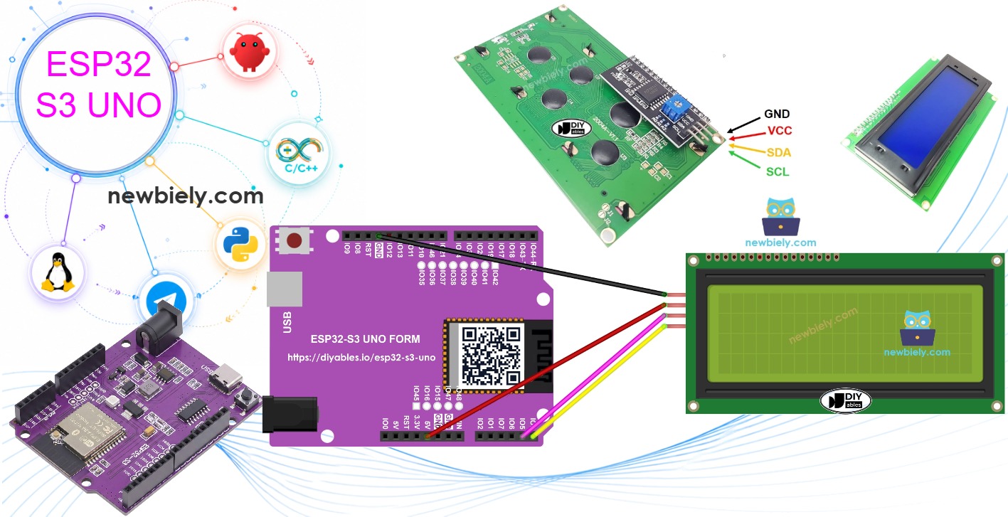
Hardware Preparation
| 1 | × | ESP32 S3 Uno-form Board | |
| 1 | × | USB Cable Type-A to Type-C (for USB-A PC) | |
| 1 | × | USB Cable Type-C to Type-C (for USB-C PC) | |
| 1 | × | LCD 20x4 | |
| 1 | × | Jumper Wires | |
| 1 | × | 5V to 3.3V Level Converter (optional, for SDA and SCL) |
Or you can buy the following kits:
| 1 | × | DIYables Sensor Kit (18 sensors/displays) |
Additionally, some of these links are for products from our own brand, DIYables .
Buy Note: Alternatively, you can assemble the LCD I2C display using LCD 2004 Display and PCF8574 I2C Adapter Module.
Overview of LCD I2C 20x4
A 20x4 LCD with an I2C backpack is a simple way to show a lot of text from your ESP32 S3 Uno. The backpack board on its back turns the many parallel LCD pins into just two I2C signal wires. This saves pins for your other parts.
Pinout
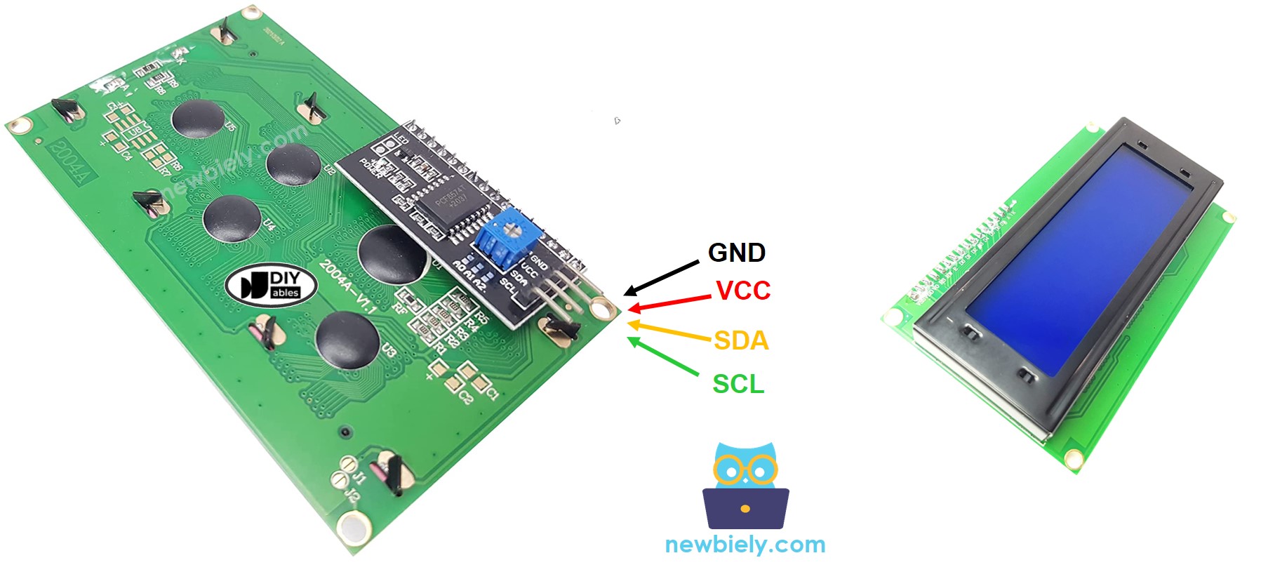
The LCD 20x4 I2C module has four pins. Two of them give power, and two of them carry the I2C signals.
| Pin | What It Does |
|---|---|
| GND | Connect to ground (0V) |
| VCC | Power for the LCD, connect to 5V |
| SDA | I2C data signal |
| SCL | I2C clock signal |
LCD Coordinate
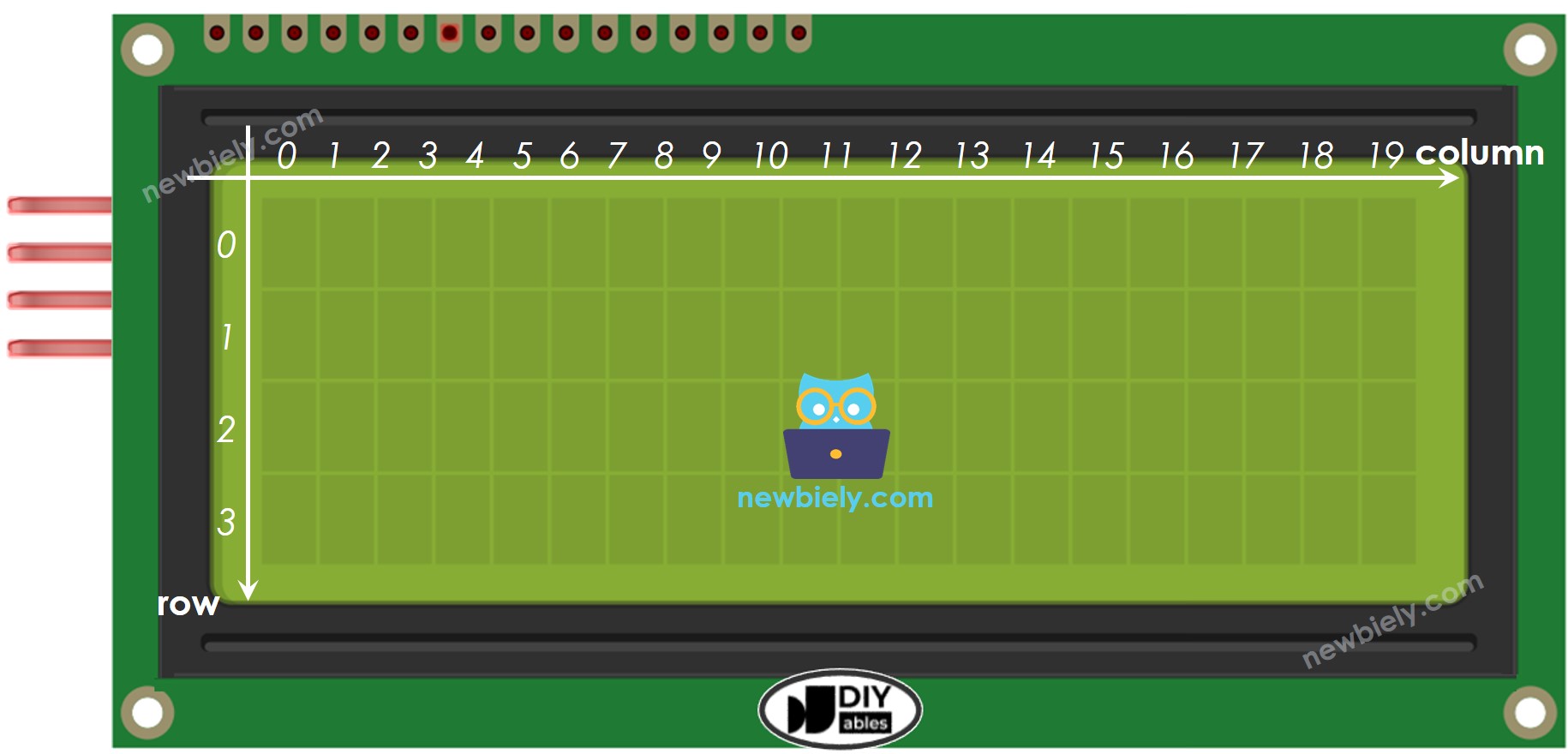
You tell the LCD where to write by giving it a column and a row. The screen has 20 columns and 4 rows, and both numbers start at 0. So the top-left cell is (0, 0) and the bottom-right cell is (19, 3).
ESP32 S3 Uno Pinout
The image below shows the pinout of the ESP32 S3 Uno form board. Use it to find the SDA and SCL header pins and their GPIO numbers before you wire the LCD.

Wiring Diagram
The LCD talks over I2C, so it goes to the SDA and SCL header pins of the ESP32 S3 Uno. Note that A4 and A5 are NOT I2C pins on this board.
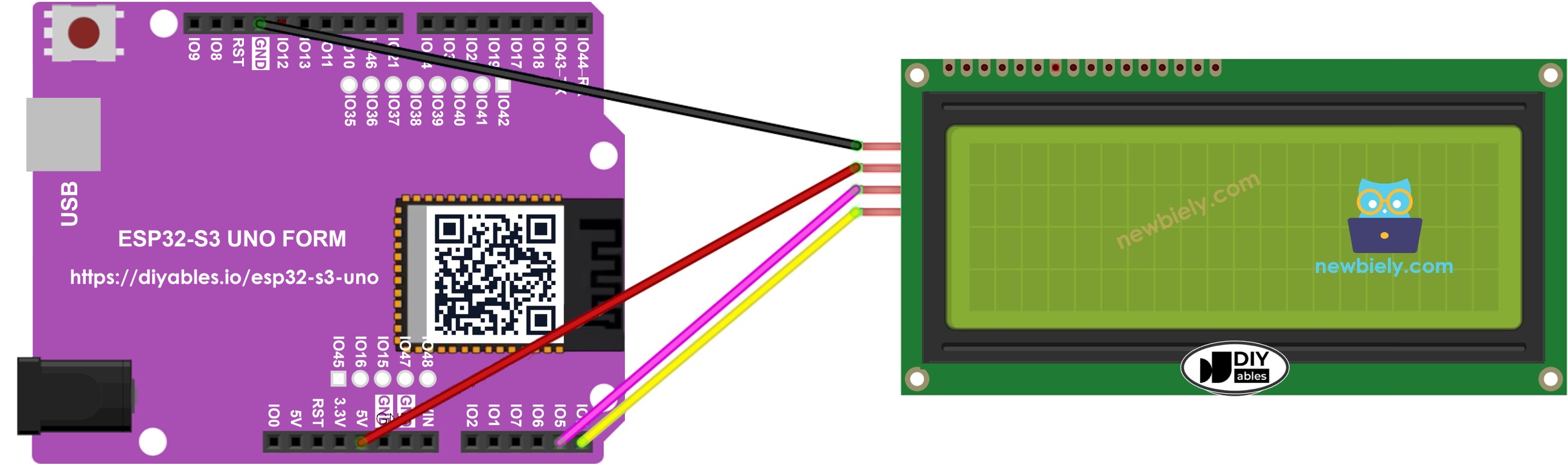
This image is created using Fritzing. Click to enlarge image
| LCD I2C Pin | ESP32 S3 Uno Pin |
|---|---|
| VCC | 5V |
| GND | GND |
| SDA | SDA (GPIO8) |
| SCL | SCL (GPIO9) |
WARNING
The LCD runs on 5V. Many LCD I2C backpacks pull SDA and SCL up to their VCC, so these lines can sit at 5V. The ESP32 S3 Uno pins are NOT 5V tolerant. To keep the board safe, pass SDA and SCL through a 5V to 3.3V level converter.
How To Program For LCD I2C
The DIYables_LCD_I2C library does the hard work for you. You only need a few lines of code to set up the screen and print text.
Include the library
Create the LCD object
Give it the I2C address, the number of columns, and the number of rows.
Start the LCD
Call these two functions once in setup() to start the screen and turn on its backlight.
Move the cursor
Pick the column and the row where the next text will start.
Print a message
※ NOTE THAT:
The I2C address can be different from one LCD maker to another. This example uses 0x27, the address given by DIYables. If your screen stays blank, run an I2C scanner sketch to find your LCD's address.
ESP32 S3 Uno Code
The sketch below starts the LCD and writes one line of text on each of the four rows. All the work happens in setup(), so the text appears once and stays on the screen. The loop() is empty.
The code calls lcd.init() with no pin numbers. On the ESP32 S3 Uno, the Wire library uses the SDA (GPIO8) and SCL (GPIO9) header pins by default, so no pin change is needed.
Detailed Instructions
Follow these steps in order:
- New to the ESP32 S3 Uno? Follow ESP32 S3 Uno - Getting Started first.
- Wire it up as shown in the diagram.
- Connect the board to your computer with a USB Type-C cable.
- Open Arduino IDE, choose the ESP32S3 Dev Module board and the correct COM port.
- Open the Library Manager by clicking the Libraries icon on the left side of Arduino IDE.
- Search for the library by typing "DIYables LCD I2C", and find the DIYables_LCD_I2C library by DIYables.
- Install it by clicking the Install button.
- Search for DIYables LCD I2C created by DIYables.io and click the Install button.
- Copy the code above and paste it into Arduino IDE.
- Upload the code by clicking the Upload button.
- Check the LCD. You should see four lines of text.
- Tip: Change the text and the cursor positions, then upload again to see how the layout changes.
The USB port may not give enough power for the LCD backlight. If the screen is dim or shows no characters, power the LCD from an external 5V source. A power splitter set makes this easy, as shown below:
https://newbiely.com/images/tutorial/how-to-power-esp32-s3-uno-and-external-components.jpg
Video Tutorial
Watch the video below to see this ESP32 S3 Uno project step by step.
The video demo is a small RFID door lock. It shows the system state on the 20x4 LCD, opens a servo door for the right card, and beeps a buzzer. After three wrong cards, it locks for a short time. The demo code is below. It needs the MFRC522 and ESP32Servo libraries.
WARNING
In this demo, the RFID SS pin goes to D10 (GPIO10), the RFID RST pin goes to D9 (GPIO46), the servo goes to D6 (GPIO3) and the buzzer goes to D8 (GPIO21). The RFID module uses SPI on D11 (GPIO11), D12 (GPIO13) and D13 (GPIO12). D6 (GPIO3) and D9 (GPIO46) are boot strapping pins. If the board does not boot or upload, unplug the servo and RFID RST wires, upload, then plug them back in.
FAQ
Which pins of the ESP32 S3 Uno do I use for the LCD 20x4 I2C?
Use the SDA (GPIO8) and SCL (GPIO9) header pins. On the ESP32 S3 Uno, A4 and A5 are only analog pins, not I2C. The Wire library uses GPIO8 and GPIO9 by default, so your code needs no pin numbers.
Can I power the LCD 20x4 from 3.3V?
Most LCD 2004 modules are made for 5V. At 3.3V the text is often too faint to read. Power the LCD from 5V, and use a level converter on SDA and SCL to keep the ESP32 S3 Uno pins at 3.3V.
Is the I2C 5V signal safe for the ESP32 S3 Uno?
The ESP32 S3 Uno pins are NOT 5V tolerant. Many LCD backpacks pull SDA and SCL up to 5V. A 5V to 3.3V level converter on these two lines is the safe choice.
How do I find the I2C address of my LCD 20x4?
Common addresses are 0x27 and 0x3F. Upload an I2C scanner sketch and open the Serial Monitor. It prints the address of every I2C device it finds. Put that address in the DIYables_LCD_I2C line.
Is the code different from the Arduino UNO R4 code?
No. The DIYables_LCD_I2C code is the same. Only the wiring changes: on the UNO R4 the LCD goes to A4 and A5, but on the ESP32 S3 Uno it goes to the SDA and SCL header pins.
What if my project needs more pins than the Uno headers give?
The ESP32 S3 Uno has two extra rows of holes with more GPIOs. GPIO15 and GPIO16 work as I/O, PWM and analog. GPIO45 and GPIO35 to GPIO42 work as I/O and PWM. GPIO47 and GPIO48 are output only, with PWM. Solder pin headers to use them, and write the GPIO number in code. For an LCD project with extra buttons, GPIO35 to GPIO42 are good inputs; do not use GPIO47 or GPIO48 for inputs. Two warnings: (1) GPIO47 and GPIO48 may run at 1.8V instead of 3.3V on some modules (especially ones with "V" in the name, like R8V or R16V), so 3.3V devices can be damaged or act strangely. (2) GPIO0, GPIO3 (D6), GPIO45 and GPIO46 (D9) are boot strapping pins, and a wrong connection can stop the board from booting or uploading code. Use the other extra pins first.
Troubleshooting
| Problem | Possible Cause | Solution |
|---|---|---|
| No COM port in Arduino IDE | USB driver missing or the board is not in upload mode | Install the CP210x or CH340 driver. Or hold BOOT while you press RESET, then upload |
| LCD backlight is on but no text | Wrong I2C address | Run an I2C scanner sketch and use the address it prints, often 0x27 or 0x3F |
| LCD shows a row of white boxes | Contrast is not set right | Turn the small blue potentiometer on the back of the LCD slowly |
| Nothing works and the backlight is off | Wiring or power problem | Check VCC goes to 5V and GND goes to GND. Try an external 5V supply |
| LCD does not respond | SDA and SCL wired to A4 and A5 | Move the wires to the SDA (GPIO8) and SCL (GPIO9) header pins |
| Text is dim or flickers | USB power is not enough | Power the LCD from an external 5V source with a shared GND |
| Compile error about DIYables_LCD_I2C.h | Library not installed | Install the DIYables_LCD_I2C library from the Library Manager |
| Text is cut off or wraps wrongly | Text is longer than 20 characters | Keep each line to 20 characters or less and set the cursor for each row |