
ESP32 S3 UNO - DIYables Bluetooth App Slider
Overview
This ESP32 S3 Uno Bluetooth slider tutorial shows you how to drag two sliders on your phone and send their values to the ESP32 S3 Uno form board over BLE. The DIYables Bluetooth STEM app gives you two independent sliders with a 0 to 100 range. You can use them to dim LEDs, set a motor speed or move a servo, with no wires between the phone and the board.
In this tutorial, you will:
- Install the DIYables Bluetooth library in the Arduino IDE
- Upload the BLE slider example to the ESP32 S3 Uno
- Connect the DIYables Bluetooth app and read the slider values in the Serial Monitor
- Change the slider range and step size in code
- Map the values to PWM for LED brightness, servo angle and motor speed
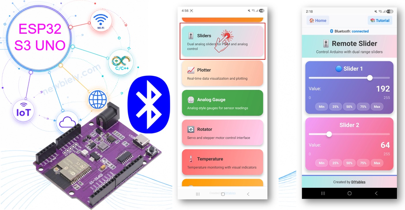
※ NOTE THAT:
The ESP32 S3 Uno supports only BLE (Bluetooth Low Energy). It has no Bluetooth Classic radio, so the BluetoothSerial library and the Classic Bluetooth example (Esp32Bluetooth_Slider) do not work on it. This page uses only the BLE example (Esp32BLE_Slider). The good news: BLE works with the app on both Android and iOS, and you do not need to pair the board first.
Features
The slider app turns your phone into a small control panel with two faders. Here is what it gives you.
Two independent sliders
Each slider sends its own value. You can control two outputs at the same time, for example two LEDs or two servos.
Range and step you can change
The default range is 0 to 100 with a step of 1. You can set a new minimum, maximum and step in code, even while the sketch runs.
Real-time values
The app sends a new value as soon as you move a slider. The board gets it right away and can update its output.
Ready for PWM
A value from 0 to 100 maps easily to the 0 to 255 range of analogWrite(), so LED dimming and motor speed are only one line of code.
BLE on Android and iOS
BLE works on both phone types and needs no manual pairing. It also uses less power than Classic Bluetooth.
Hardware Preparation
Or you can buy the following kits:
| 1 | × | DIYables Sensor Kit (18 sensors/displays) |
Additionally, some of these links are for products from our own brand, DIYables .
Buy Note: For controlling multiple servo motors, use the PCA9685 16 Channel PWM Servo Driver Module to save MCU pins and simplify wiring.
ESP32 S3 Uno Pinout
The image below shows the pinout diagram of the ESP32 S3 Uno form board. Use it to find the Uno header pins (D3, D5, D9, D10…) and their GPIO numbers when you add LEDs or servos to this project.

ESP32 S3 Uno Code
You can test the basic example with only the board, a USB cable and your phone. The steps below install the library and upload the BLE slider sketch. LEDs are optional and only show the PWM output.
Detailed Instructions
- New to the ESP32 S3 Uno? Follow ESP32 S3 Uno - Getting Started first.
- Connect the board to your computer with a USB Type-C cable.
- Open Arduino IDE, choose the ESP32S3 Dev Module board and the correct COM port.
- Set the partition scheme: go to Tools > Partition Scheme and pick "Huge APP (3MB No OTA/1MB SPIFFS)". The Bluetooth library is big and does not fit in the default app space.
- Open the Library Manager: click the Libraries icon on the left bar of the Arduino IDE.
- Find the library: search "DIYables Bluetooth" and find the DIYables Bluetooth library by DIYables.
- Install it: click the Install button.
- Search for DIYables Bluetooth created by DIYables and click the Install button.
- Install the dependencies: when the IDE asks about other libraries, click Install All.
- Tip: if the upload fails with a "Sketch too big" message, check the partition scheme again. It often resets when you change the board.
ESP32 S3 Uno BLE Code (works with the app on Android and iOS)
This sketch starts a BLE server named "ESP32BLE_Slider" and adds the slider app to it. Each new slider value is printed to the Serial Monitor and turned into a PWM signal on D9 (GPIO46) and D10 (GPIO10). When the phone connects, the board sends the last values back, so the sliders in the app show the right position.
If you want to see the PWM output, wire one LED to each pin like this:
| LED Pin | ESP32 S3 Uno Pin |
|---|---|
| LED 1 anode (+) through a 220 ohm resistor | D9 (GPIO46) |
| LED 2 anode (+) through a 220 ohm resistor | D10 (GPIO10) |
| LED 1 and LED 2 cathode (-) | GND |
WARNING
D9 (GPIO46) is a boot strapping pin on the ESP32 S3 Uno. The board reads it at startup to choose the boot mode. An LED with a resistor is normally fine, but if the board will not boot or upload while the LED is connected, unplug the wire from D9, upload, and then plug it back in.
- Load the example: in Arduino IDE, go to File Examples DIYables Bluetooth Esp32BLE_Slider, or copy the code below into the editor.
- Upload: click the Upload button.
- Open the Serial Monitor and set it to 115200 baud.
- Check the output. It should look like this:
- Tip: the library example uses other pin numbers. Keep the D9 (GPIO46) and D10 (GPIO10) numbers from the code above so they match the Uno header positions.
Mobile App
The app is where you move the sliders. Because the ESP32 S3 Uno uses BLE, you connect from inside the app and skip the phone's Bluetooth pairing menu.
- Open the app and grant the permissions it asks for:
- Nearby Devices (Android 12+) or Bluetooth (iOS), needed to scan and connect
- Location (Android 11 and below only), needed by older Android versions to scan for BLE devices
- Turn on Bluetooth on your phone.
- Scan: on the home screen, tap the Connect button.
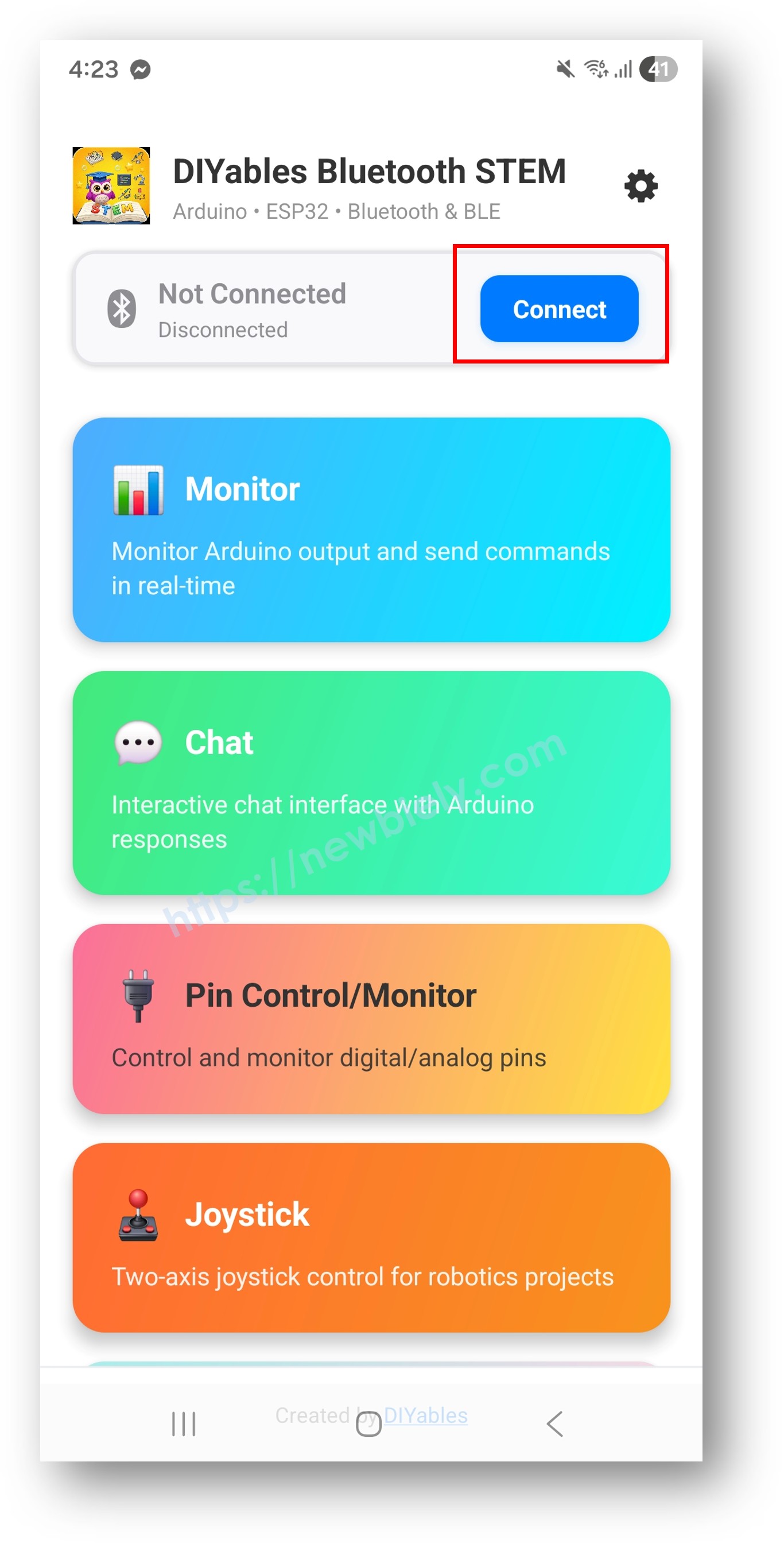
- Connect: tap "ESP32BLE_Slider" in the scan results.
- Open the Slider: the app returns to the home screen after it connects. Tap the Slider app.
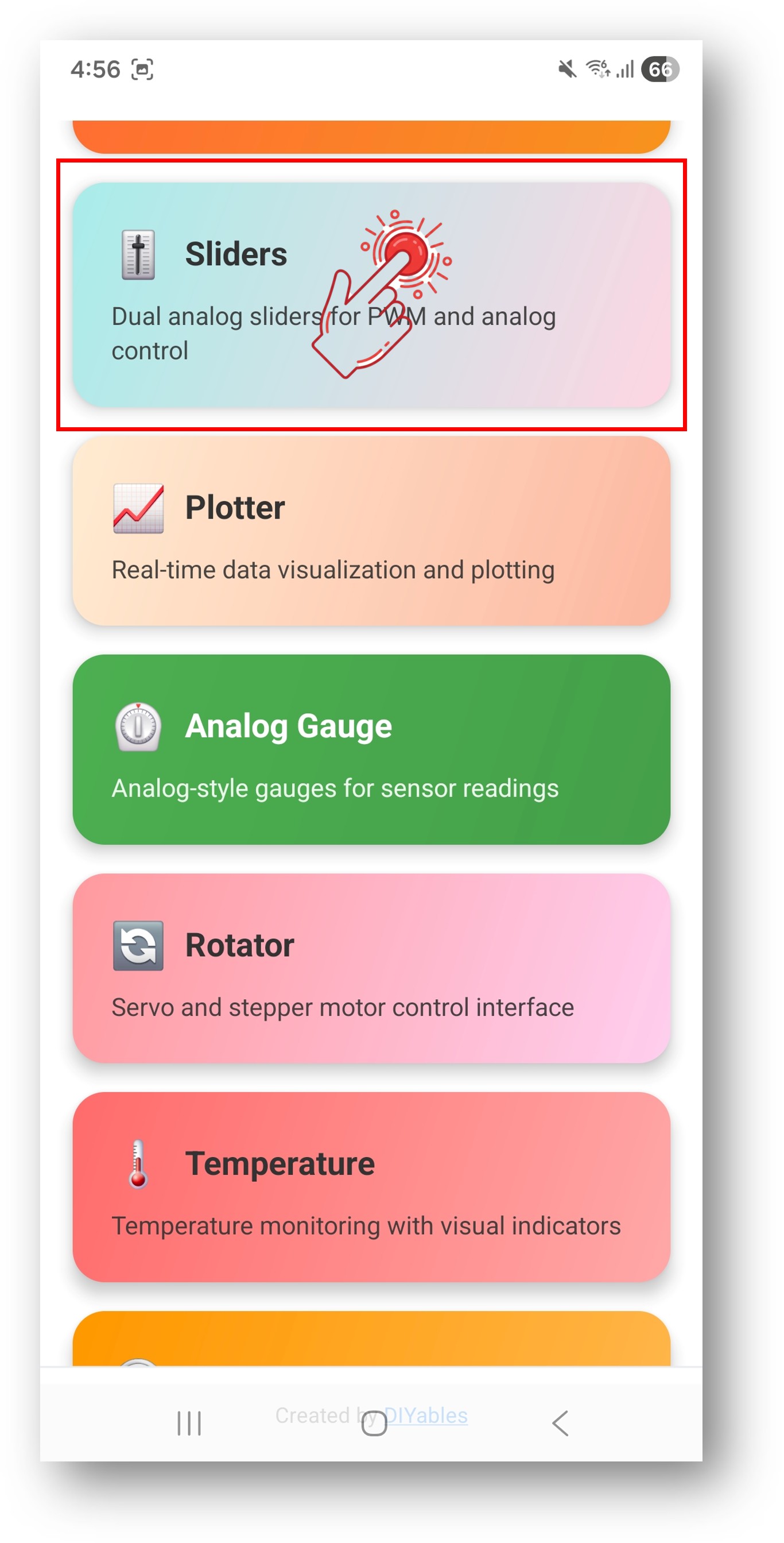
※ NOTE THAT:
You can tap the settings icon on the home screen to show or hide apps. For more details, read the DIYables Bluetooth App User Manual.
- Move the sliders: drag each one to change its value from 0 to 100.
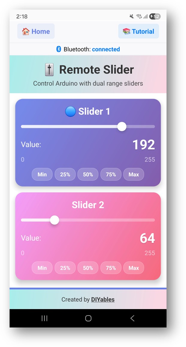
Go back to the Serial Monitor in the Arduino IDE. You will see each new pair of values as you move the sliders:
If you wired the LEDs, they get brighter as you move the sliders up.
Creative Customization - Adapt the Code to Your Project
The example prints the values and dims two outputs. The snippets below show the library functions you can use to shape the sliders and react to them in your own ESP32 S3 Uno project.
Set Default Slider Values
The two variables hold the slider positions. Give them a start value, and the app shows that position when it connects.
Customize Slider Range and Step
You set the range and step when you create the slider object. You can also change them later and read them back.
Handle Configuration Request from App
When the app opens the slider screen, it asks the board for the current values. Answer in the onGetConfig() callback, so the sliders do not jump back to 0.
Send Values to App
The ESP32 S3 Uno can also move the sliders on the phone by itself, for example after a button press or a sensor change.
Handle Connection Events
These two callbacks tell you when the phone connects or leaves. A good habit is to stop motors when the connection drops.
How to Use the Sliders
It helps to know what each part of the screen does before you build on it.
App Interface Controls
Slider 1 and Slider 2
Two separate sliders. Drag each one up or down to set its value.
Value display
A number next to each slider shows its current value, so you always know what the board receives.
Value Ranges
Each slider runs from 0 to 100 by default. You can change the range and step in code. To drive a PWM pin, map the value to 0 to 255 with map(value, 0, 100, 0, 255).
Programming Examples
These examples show real uses for the slider values. Each one is a part of a sketch, so add it to the full BLE example above.
Basic Slider Handler
This is the smallest useful callback. It stores the two values and prints them, and you add your own logic at the end.
LED Brightness Control
Each slider sets the brightness of one LED. The analogWrite() function works on the ESP32 S3 Uno, so no special PWM setup is needed. Use the same LED wiring as the main example: D9 (GPIO46) and D10 (GPIO10).
Servo Position Control
Each slider moves one servo from 0° to 180°. Install the "ESP32Servo" library by Kevin Harrington first. The standard Servo library does not run on the ESP32 S3 Uno.
| Servo Pin | ESP32 S3 Uno Pin |
|---|---|
| VCC (red) of both servos | 5V |
| GND (brown) of both servos | GND |
| Signal (orange) of servo 1 | D9 (GPIO46) |
| Signal (orange) of servo 2 | D10 (GPIO10) |
Motor Speed with Direction
Here slider 1 sets the motor speed and slider 2 picks the direction. A value of 50 or more means forward, below 50 means reverse. Connect the speed input of your motor driver to D9 (GPIO46) and the direction input to D8 (GPIO21).
RGB LED Color Control
Two sliders can mix three colors. Slider 1 sets red, slider 2 sets blue, and green is the average of both. Wire the red, green and blue legs to D9 (GPIO46), D10 (GPIO10) and D11 (GPIO11), each through a 220 ohm resistor.
Advanced Programming Techniques
Once the basics work, you can change how the values are handled before you use them.
Value Smoothing
A sudden jump from 0 to 100 can make a motor jerk. This class moves the output toward the new target in small steps every 10 ms, so changes feel soft.
Slider with Dead Zone
A dead zone around the middle gives you a clear "stop" position. Values from 45 to 55 turn the output off, and the rest sets the speed.
Threshold-Based Control
You can also split a slider into levels and switch digital outputs. Slider 1 turns on zero, one or three outputs on D2 (GPIO18), D4 (GPIO19) and D7 (GPIO14). Slider 2 still sets PWM on D10 (GPIO10).
Preset Value System
Presets let you jump to saved positions with one call. The function updates the outputs and sends the new values to the app, so the sliders move too.
Rate Limiting
If you drag a slider fast, the app sends many values. This check makes sure the output changes at most once every 50 ms.
Hardware Integration Examples
The same callback can drive bigger hardware. These two examples show an addressable LED strip and two fans.
LED Strip Control
Slider 1 sets the brightness and slider 2 sets the hue of a WS2812B strip. You need a library like FastLED or Adafruit NeoPixel. Connect the strip data line to D7 (GPIO14). Most WS2812B strips read the 3.3V data signal fine, but some need a level shifter.
Fan Speed Control
Small fans often do not start at a low PWM value. This code keeps the fan off below a threshold and starts it at a safe minimum speed. Drive each fan through a transistor or MOSFET module from D9 (GPIO46) and D10 (GPIO10), never straight from the pin.
Why BLE Only on the ESP32 S3 Uno?
Some ESP32 boards offer both BLE and Classic Bluetooth. The ESP32 S3 Uno has a BLE radio only, so the choice is made for you. That is fine for this project, as the table shows.
| Feature | BLE on the ESP32 S3 Uno |
|---|---|
| iOS Support | Yes |
| Android Support | Yes |
| Power Use | Low |
| Range | About 30 to 100 m in open space |
| Pairing | Not needed, connect from the app |
| Example Name | Esp32BLE_Slider |
| Classic Bluetooth (BluetoothSerial) | Not supported on this board |
Video Tutorial
Watch the video below to see this ESP32 S3 Uno project step by step. In the demo, each slider moves one servo motor. The servo signals go to D3 (GPIO17) and D5 (GPIO20), and both servos take power from the 5V pin.
| Servo Pin | ESP32 S3 Uno Pin |
|---|---|
| VCC (red) of both servos | 5V |
| GND (brown) of both servos | GND |
| Signal (orange) of servo 1 | D3 (GPIO17) |
| Signal (orange) of servo 2 | D5 (GPIO20) |
The code used in the demo is below. It needs the "ESP32Servo" library by Kevin Harrington.
Common Issues and Debugging
Most slider problems come from the connection, the range settings or the output pins. Check these first.
The device does not show up in the app
Make sure the sketch is uploaded and the board is powered. Turn on Bluetooth on your phone, and on Android 11 and below also turn on Location. Look for "ESP32BLE_Slider", not a Classic Bluetooth name.
The sliders move but nothing happens
Look at the connection status in the app and in the Serial Monitor. If you see no "Bluetooth connected!" line, disconnect and connect again.
The values do not reach the full range
Check the range in DIYables_BluetoothSlider(min, max, step) and the numbers in your map() call. Print the received values in the Serial Monitor to see what really arrives.
The sliders jump back to 0 after a reconnect
Store the values in global variables and send them back in the onGetConfig() and setOnConnected() callbacks.
The connection drops often
Move the phone closer to the ESP32 S3 Uno and away from other BLE devices. A weak USB port can also cause drops.
Sketch too big
Go to Tools > Partition Scheme and pick "Huge APP (3MB No OTA/1MB SPIFFS)" or "No OTA (Large APP)". The default scheme leaves only about 1.2 MB for your code, which is too small for the Bluetooth library.
Debug Tips
This helper prints both slider values and their PWM values in one block. Call it inside onSliderValue() while you test.
Project Ideas
Two sliders are a simple input, but they fit many projects. Here are some ideas for your ESP32 S3 Uno.
Lighting Control Projects
A room light dimmer, an RGB color mixer, an LED strip brightness and hue control, or a small stage light dimmer.
Motor Control Projects
A robot speed control, a fan speed regulator, a pump flow control, a pan-tilt camera mount with two servos, or a conveyor belt speed control.
Audio Projects
A volume control, a tone frequency selector or an equalizer band.
Home Automation
A heating or cooling level control, a window blind position control, or an irrigation flow control.
Integration with Other Bluetooth Apps
The slider works well together with other DIYables Bluetooth apps on the same board.
Combine with Bluetooth Joystick
Use slider 1 as a speed limit and the joystick for direction. The joystick values are scaled by the slider before they reach the motors.
Combine with Bluetooth Digital Pins
Use digital pins as on/off switches and sliders for the level. A PWM output only runs when its switch pin is HIGH. Here the switch pins are D2 (GPIO18) and D4 (GPIO19), and the PWM outputs are D9 (GPIO46) and D10 (GPIO10).
Next Steps
When the slider works, try these other examples on your ESP32 S3 Uno:
- Bluetooth Joystick for 2D direction control
- Bluetooth Rotator for angle control
- Bluetooth Digital Pins for on/off control
- Bluetooth Monitor to watch your slider values on the phone
- Multiple Bluetooth Apps to combine the slider with other controls
Support
If you get stuck, these places can help:
- The API Reference documentation of the DIYables Bluetooth library
- The Arduino community forums
FAQ
Does the ESP32 S3 Uno support Classic Bluetooth for the slider?
No. The ESP32 S3 Uno has BLE only. Use the Esp32BLE_Slider example. The Esp32Bluetooth_Slider example uses BluetoothSerial and will not compile or work on this board.
Which library do I need for the Bluetooth slider on the ESP32 S3 Uno?
Install the "DIYables Bluetooth" library by DIYables and its dependencies. The ESP32 S3 Uno uses platforms/DIYables_Esp32BLE.h, while the UNO R4 WiFi uses platforms/DIYables_ArduinoBLE.h. The slider functions are the same on both boards.
Does analogWrite() work on the ESP32 S3 Uno?
Yes. The esp32 core supports analogWrite() with values from 0 to 255, so you can map the slider value and write it directly. You do not need ledcSetup() or ledcAttachPin() for this project.
Why are my LEDs dimmer than on a 5V board?
The ESP32 S3 Uno pins output 3.3V, not 5V. An LED with a 220 ohm resistor still works but looks a bit dimmer. For more brightness, use a smaller resistor (not below about 100 ohm) or drive the LED through a transistor.
Can I power two servos from the ESP32 S3 Uno 5V pin?
Two small SG90 servos with no load usually work from the 5V pin. Bigger servos, or servos under load, can pull current spikes that reset the board. In that case use an external 5V supply and connect its GND to the ESP32 S3 Uno GND.
What if my project needs more pins than the Uno headers give?
The ESP32 S3 Uno has two extra rows of holes with more GPIOs: GPIO15 and GPIO16 (I/O, PWM, analog), GPIO45 and GPIO35 to GPIO42 (I/O, PWM), and GPIO47/GPIO48 (output only, PWM). Solder pin headers to use them and write the GPIO number in code. For extra LEDs, servos or motor drivers, GPIO35 to GPIO42 are a good choice, because every one of them supports PWM. Be careful with two things. First, GPIO47 and GPIO48 may run at 1.8V instead of 3.3V on some modules (especially ones with "V" in the name, like R8V or R16V), so 3.3V devices can be damaged or act strangely. Second, GPIO0, GPIO3 (D6), GPIO45 and GPIO46 (D9) are boot strapping pins, and a wrong connection can stop the board from booting or uploading code. Use the other extra pins first.
Troubleshooting
| Problem | Possible Cause | Solution |
|---|---|---|
| No COM port in Arduino IDE | USB driver missing or board not in download mode | Install the CP210x or CH340 driver, try another USB cable, or hold BOOT while you press RESET |
| Upload fails with Sketch too big | Default partition scheme is too small for BLE | Select Huge APP (3MB No OTA/1MB SPIFFS) in Tools > Partition Scheme |
| ESP32BLE_Slider not in the scan list | Sketch not running, or phone Bluetooth or Location is off | Check the Serial Monitor for Waiting for Bluetooth connection, then turn on Bluetooth (and Location on Android 11 and below) |
| Compile error about BluetoothSerial | Classic Bluetooth example used | Use the Esp32BLE_Slider example, as the ESP32 S3 Uno has no Classic Bluetooth |
| LED does not change brightness | Wrong pin, missing resistor or LED reversed | Wire the LEDs to D9 (GPIO46) and D10 (GPIO10) with 220 ohm resistors and check the LED direction |
| Board does not boot with the LED or servo connected | D9 (GPIO46) is a boot strapping pin | Unplug the wire from D9 during boot or upload, then plug it back in |
| Board resets when the servos move | Servos pull too much current from the 5V pin | Use an external 5V supply for the servos and share GND with the board |
| Serial Monitor shows strange characters | Wrong baud rate | Set the Serial Monitor to 115200 baud |