
ESP32 S3 UNO - TCS3200D/TCS230 Color Sensor
This ESP32 S3 Uno color sensor tutorial shows you how to wire a TCS3200D/TCS230 module to the ESP32 S3 Uno form board and read the color of an object. You will calibrate this RGB detector for your own light and distance, then turn its raw pulse widths into clean 0-255 red, green and blue values in the Serial Monitor.
In this tutorial, you will:
- Wire the TCS3200D/TCS230 color recognition sensor to the ESP32 S3 Uno
- Learn how the S0-S3 pins pick the color filter and output scaling
- Run a calibration sketch to find the min and max pulse widths
- Read RGB values with Arduino IDE code and the pulseIn() function
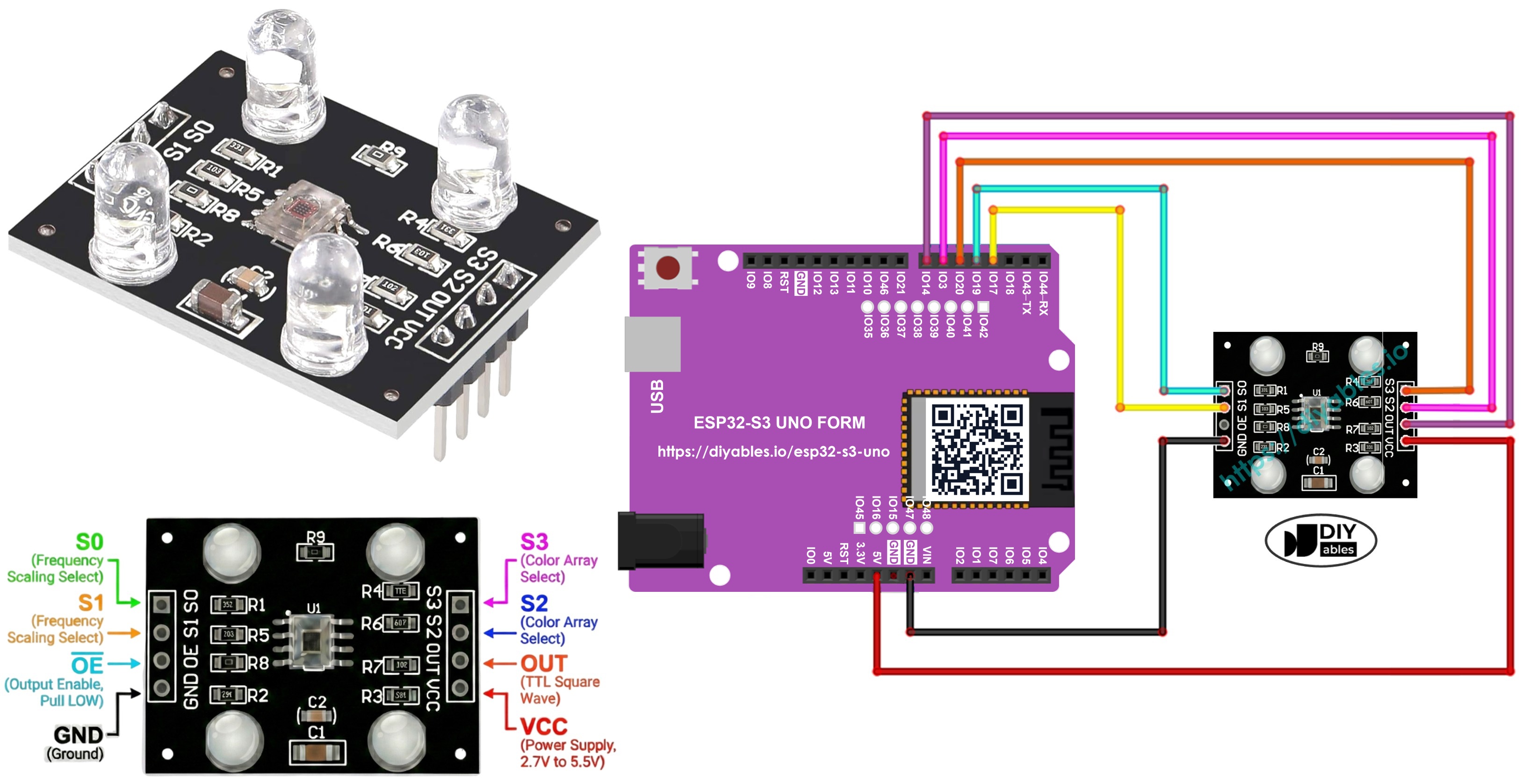
Hardware Preparation
| 1 | × | ESP32 S3 Uno-form Board | |
| 1 | × | USB Cable Type-A to Type-C (for USB-A PC) | |
| 1 | × | USB Cable Type-C to Type-C (for USB-C PC) | |
| 1 | × | TCS3200D/TCS230 Color Recognition Sensor Module | |
| 1 | × | Jumper Wires |
Or you can buy the following kits:
| 1 | × | DIYables Sensor Kit (18 sensors/displays) |
Additionally, some of these links are for products from our own brand, DIYables .
Overview of TCS3200D/TCS230 Color Sensor
Before you write any code, it helps to know what is inside the sensor. Once you understand how it "sees" color, the calibration step later will make much more sense.
The TCS3200D/TCS230 module is built around an 8x8 grid of 64 photodiodes. Sixteen of them sit behind red filters, sixteen behind green filters, sixteen behind blue filters, and the last sixteen have no filter at all (clear). The chip turns the amount of light it sees into a square-wave signal. When you switch between the filters and measure that signal, you can work out how much red, green and blue light the object reflects.
Most modules also carry a few white LEDs around the sensor. They light up the target evenly, so your readings stay steady even in a dim room.
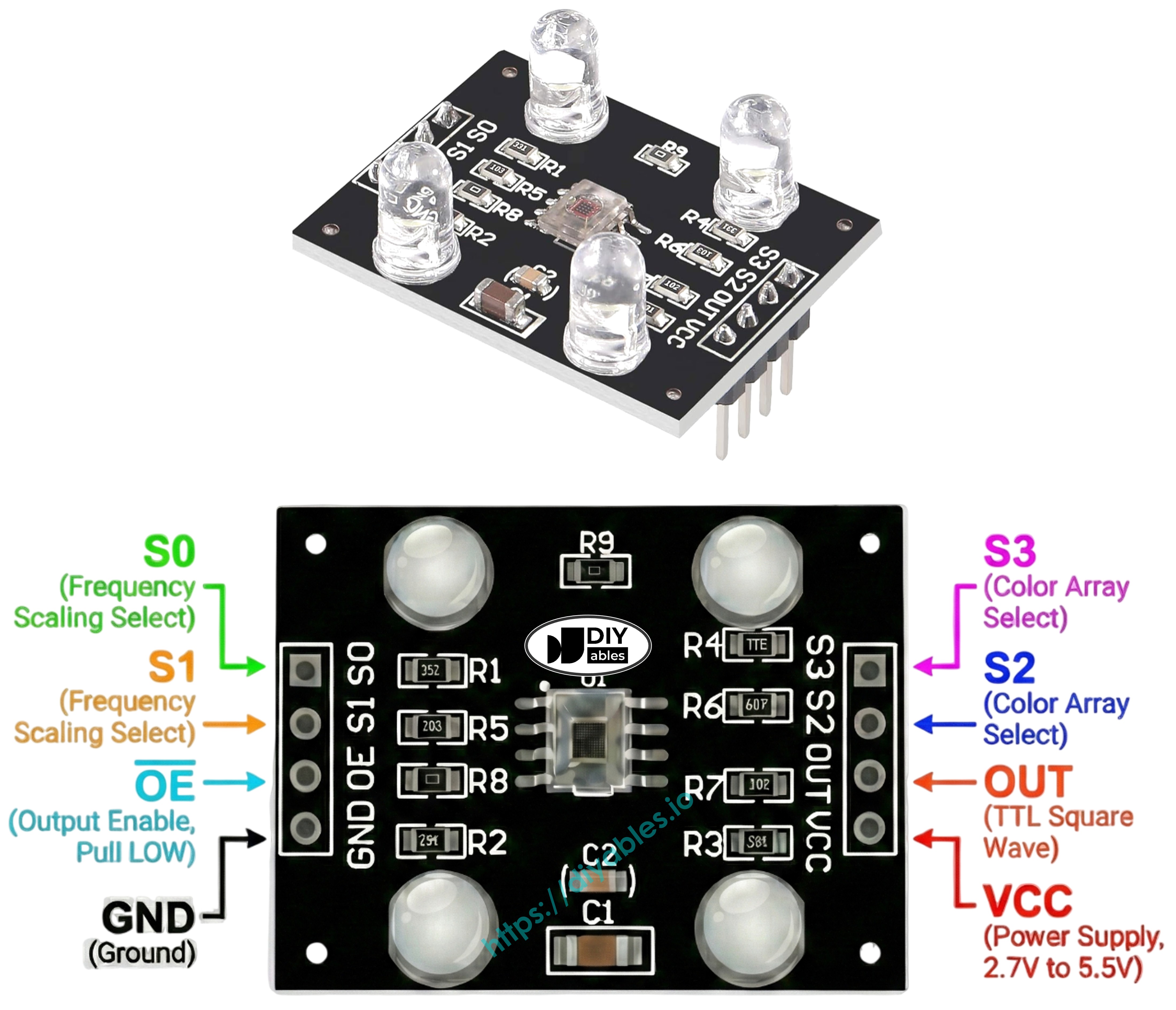
Pinout
The module has a small row of pins. Two of them power it, four of them control it, and one sends the color signal back to the ESP32 S3 Uno.
Power pins
VCC is the supply pin. The chip runs from 2.7V to 5.5V, so on the ESP32 S3 Uno you should power it from 3.3V. GND goes to ground (0V).
Control pins
S0 and S1 set the output frequency scaling. S2 and S3 choose which color filter is active.
Output pins
OUT gives the square-wave frequency signal. OE is the output enable pin (active LOW). On most modules OE is already tied to GND on the board, so you can leave it unconnected. If yours is not, wire it to GND.
How It Works
The sensor needs two pieces of information from your board: which color to look at, and how fast its output signal should be. Each piece is set by a pair of control pins.
Output frequency scaling (S0, S1)
| S0 | S1 | Output Scaling |
|---|---|---|
| LOW | LOW | Power down |
| LOW | HIGH | 2% |
| HIGH | LOW | 20% |
| HIGH | HIGH | 100% |
Color filter selection (S2, S3)
| S2 | S3 | Active Filter |
|---|---|---|
| LOW | LOW | Red |
| LOW | HIGH | Blue |
| HIGH | LOW | Clear (no filter) |
| HIGH | HIGH | Green |
Reading the signal
The OUT pin sends a square wave between roughly 2 Hz and 500 kHz. More light of the chosen color means a higher frequency and a shorter pulse. The code in this tutorial measures the pulse width with pulseIn(). After calibration, it converts that pulse width into an RGB value from 0 to 255.
Tips for Stable Readings
Color readings change a lot with light and distance. A few simple habits keep them repeatable:
- Hold the sensor 1-3 cm away from the object, and keep the same angle each time.
- Turn on the module's white LEDs so the light level stays the same.
- Block room light around the sensor (a small black tube or cardboard hood works well).
ESP32 S3 Uno Pinout
The image below shows the pinout of the ESP32 S3 Uno form board. Use it to find the Uno header pins (D3 to D7) and their GPIO numbers while you wire the color sensor.

Wiring Diagram
The color sensor uses five digital pins on the ESP32 S3 Uno: four outputs for S0-S3 and one input for OUT. Wire it as shown in the image and the table below.
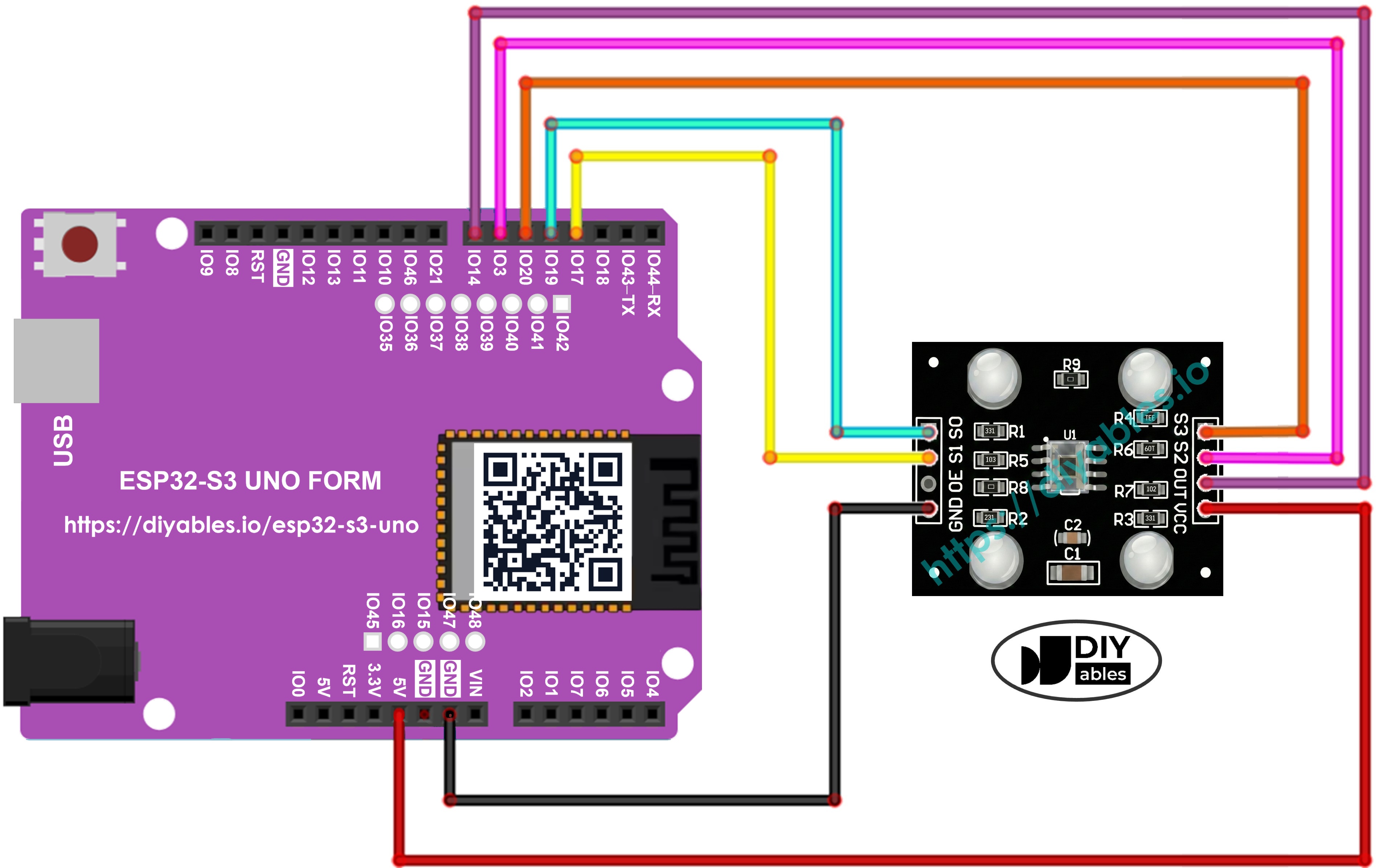
This image is created using Fritzing. Click to enlarge image
| TCS3200 Color Sensor | ESP32 S3 Uno Pin |
|---|---|
| VCC | 3.3V |
| GND | GND |
| S0 | D4 (GPIO19) |
| S1 | D3 (GPIO17) |
| S2 | D6 (GPIO3) |
| S3 | D5 (GPIO20) |
| OUT | D7 (GPIO14) |
WARNING
ESP32 S3 Uno pins are NOT 5V tolerant. Power the sensor from 3.3V, so the OUT pin also gives a 3.3V signal. If your diagram shows VCC on 5V, move that one wire to 3.3V. If you must run the module at 5V, put a level shifter or a voltage divider (for example 10k and 20k) between OUT and D7 (GPIO14).
WARNING
S2 is wired to D6, which is GPIO3 on the ESP32 S3 Uno. GPIO3 is a boot strapping pin. The board reads it at power-up to choose its boot mode. S2 is an input on the sensor, so it normally does not cause problems. If the board ever fails to boot or upload, unplug the S2 wire, upload the code, then plug it back in.
ESP32 S3 Uno Code - Calibration (Pulse Width)
You need to calibrate the sensor first, because its raw numbers depend on your setup. LED brightness, distance, how shiny the surface is, and room light all shift the readings. This sketch finds the smallest and largest pulse width for each color, so the next sketch can map them to a true 0-255 range.
The code sets S0 HIGH and S1 LOW for 20% scaling, then reads red, green and blue one after another. It keeps the lowest and highest value it has seen for each color and prints them every loop.
Detailed Instructions
- New to the ESP32 S3 Uno? Follow ESP32 S3 Uno - Getting Started first.
- Wire it up as shown in the diagram.
- Connect the board to your computer with a USB Type-C cable.
- Open Arduino IDE, choose the ESP32S3 Dev Module board and the correct COM port.
- Copy the code above and paste it into Arduino IDE.
- Upload the code by clicking the Upload button.
- Open the Serial Monitor and set it to 9600 baud. You will see live readings plus Min and Max rows.
- Scan some objects: a white one (like paper), a black one, and a few colored ones if you have them.
- Watch the Min and Max rows. They update on their own as the sensor finds new extremes.
- Write down the values once Min and Max stop changing, usually after 10-20 seconds.
- Tip: keep the same distance and lighting you will use later. If you move the sensor or change the light, run the calibration again.
With the output above, your calibration values are redMin = 42 and redMax = 210, greenMin = 55 and greenMax = 185, and blueMin = 60 and blueMax = 172.
ESP32 S3 Uno Code - Read RGB values
This second sketch uses your calibration numbers to turn each pulse width into an RGB value. It reads red, green and blue in turn, then uses map() to scale each one from your min-max range to 255-0. The result prints in the Serial Monitor as three simple numbers.
Detailed Instructions
- Find the calibration lines near the top of the code:
- Replace all six zeros with the numbers from your calibration. With the example values from the previous step, the lines become:
- Upload the code to the ESP32 S3 Uno.
- Hold a colored object in front of the sensor.
- Read the result in the Serial Monitor.
- Tip: if a value goes below 0 or above 255, the object is darker or brighter than anything you scanned during calibration. Run the calibration again with that object included.
The numbers now sit in the normal 0-255 RGB range. A short pulse width means more light, so it gives a high value. A long pulse width means less light, so it gives a low value.
Applications
Once your ESP32 S3 Uno can read RGB values, many fun projects open up. Here are a few ideas to try next:
- A color sorter that drops red, green and blue objects into different bins.
- A color matching game that checks if two objects have the same color.
- A line follower robot that follows a colored line on the floor.
- A quality control check that spots products with the wrong color.
- A color alarm that turns on a buzzer or LED when it sees a chosen color.
Video Tutorial
Watch the video below to see this ESP32 S3 Uno project step by step.
FAQ
Can I power the TCS3200 color sensor from 3.3V on the ESP32 S3 Uno?
Yes. The TCS3200D/TCS230 works from 2.7V to 5.5V, so 3.3V is fine. This is the best choice for the ESP32 S3 Uno, because the OUT signal then stays at 3.3V. The white LEDs may look a little dimmer, but calibration takes care of that.
Why are my RGB values negative or higher than 255?
The map() function does not clamp its result. If the sensor sees something darker or brighter than your calibration range, the value goes outside 0-255. Run the calibration again with more objects, or wrap each value with constrain(value, 0, 255).
Is the code different from the UNO R4 version?
Only the pin numbers change. The ESP32 S3 Uno code uses GPIO numbers (19, 17, 3, 20 and 14) for the D4, D3, D6, D5 and D7 headers. pulseIn(), digitalWrite() and map() work the same way, and no extra library is needed.
Do I need to calibrate again every time?
No. Calibrate again only when your setup changes: a new distance, a new angle, different room light, or a different sensor module. The min and max numbers only fit the setup you calibrated with.
What if my project needs more pins than the Uno headers give?
The ESP32 S3 Uno has two extra rows of holes with more GPIOs: GPIO15 and GPIO16 (I/O, PWM, analog), GPIO45 and GPIO35-GPIO42 (I/O, PWM), and GPIO47/GPIO48 (output only, PWM). Solder pin headers to them and use the GPIO number in your code. For this project, GPIO35-GPIO42 are a good choice for the S0-S3 outputs or the OUT input, for example to add a second color sensor. Do not use GPIO47/GPIO48 for OUT, because they are output only. Two warnings: GPIO47 and GPIO48 may run at 1.8V instead of 3.3V on some modules (especially ones with "V" in the name, like R8V or R16V), so 3.3V devices can be damaged or act strangely. GPIO0, GPIO3 (D6), GPIO45 and GPIO46 (D9) are boot strapping pins, and a wrong connection can stop the board from booting or uploading code. Use the other extra pins first.
Can the sensor tell me the color name instead of numbers?
Not by itself. It only gives you RGB numbers. You can add simple checks in your code, for example "if red is high and green and blue are low, print RED". Scan your real objects first, then pick the limits from their readings.
Troubleshooting
| Problem | Possible Cause | Solution |
|---|---|---|
| No COM port shows up in Arduino IDE | USB driver missing or bad cable | Install the CP210x or CH340 driver, try a data USB cable, or hold BOOT while you press RESET |
| Upload fails or board does not boot | S2 wire on D6 (GPIO3) pulls the boot strapping pin at power-up | Unplug the S2 wire, upload the code, then plug it back in |
| All readings are 0 | OUT not connected, or S0 and S1 both LOW (power down) | Check the OUT wire to D7 (GPIO14) and the S0 and S1 wires to D4 and D3 |
| Readings jump around a lot | Room light changes or the sensor moves | Keep a fixed distance of 1-3 cm and shield the sensor from outside light |
| RGB values go below 0 or above 255 | Object is outside the calibration range | Calibrate again with that object, or use constrain() in the code |
| Colors look wrong or mixed up | S2 and S3 wires swapped | Check that S2 goes to D6 (GPIO3) and S3 goes to D5 (GPIO20) |
| Board resets or acts strangely | Sensor powered from 5V so OUT sends 5V into a 3.3V pin | Move VCC to 3.3V, or add a level shifter on the OUT line |
| Serial Monitor shows strange characters | Wrong baud rate | Set the Serial Monitor to 9600 baud |