
ESP32 S3 UNO - RFID
This ESP32 S3 Uno RFID tutorial shows you how to connect an RC522 RFID/NFC reader to the ESP32 S3 Uno form board and read the unique ID of a card or tag. The RC522 RFID module is a cheap and popular reader, and the board talks to it over SPI. When you tap a tag on the reader, its UID shows up on the Serial Monitor. This is the first step for door locks, attendance systems and access control projects.
In this tutorial, you will:
- Learn how an RFID/NFC reader and tag work together
- Wire the RC522 module to the ESP32 S3 Uno
- Install the MFRC522 library in Arduino IDE
- Read the UID of RFID cards and key fobs with Arduino code
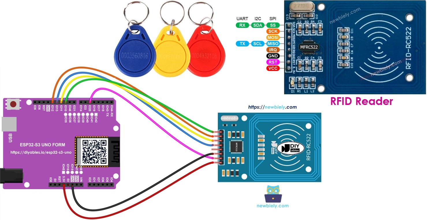
Hardware Preparation
| 1 | × | ESP32 S3 Uno-form Board | |
| 1 | × | USB Cable Type-A to Type-C (for USB-A PC) | |
| 1 | × | USB Cable Type-C to Type-C (for USB-C PC) | |
| 1 | × | RFID/NFC RC522 Kit (reader + tags) | |
| 1 | × | Jumper Wires |
Or you can buy the following kits:
| 1 | × | DIYables Sensor Kit (18 sensors/displays) |
Additionally, some of these links are for products from our own brand, DIYables .
Overview of RFID-RC522 Module
An RFID/NFC system has two parts: a reader and a tag. There are two common readers for hobby projects, the RC522 and the PN532. This tutorial uses the RC522, also sold as the RFID-RC522 module.
The RC522 can do more than one job. It can read the UID (unique ID) of a tag, change the UID (only on special tags that allow it), write data to a tag and read data back from it. Here you will focus on reading the UID, because that is what most projects need.
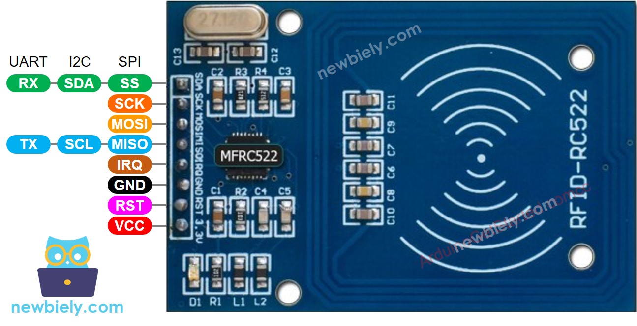
RFID-RC522 Module Pinout
The module has 8 pins. Some are always used, and others change their job based on the interface: SPI, I2C or UART. Only one interface can be active at a time.
Power pins
VCC is the power input and needs 3.3V. GND goes to ground (0V).
Control pins
RST is the reset and power-down pin. A LOW signal puts the module into hard power-down, and a rising edge resets it. IRQ is an interrupt pin that can tell the board when a tag comes close. This tutorial does not use it.
Data pins
MISO/SCL/TX works as MISO in SPI mode, SCL in I2C mode and TX in UART mode. MOSI is the SPI data input. SCK is the SPI clock. SS/SDA/RX works as SS in SPI mode, SDA in I2C mode and RX in UART mode.
※ NOTE THAT:
- The pin order can change between makers. Always follow the labels printed on your module. The image above shows the DIYables module.
- Never connect VCC to 5V. It can damage the module.
- The MFRC522 library supports SPI mode only, so this tutorial uses SPI.
How RFID/NFC Works
It helps to know what happens inside the reader before you write code. The idea is simple: the reader sends out energy, and the tag uses that energy to answer.
The reader holds a radio frequency module and an antenna. Together they make a high frequency electromagnetic field. The tag is passive, so it has no battery. Inside it is a small chip that stores data, such as the UID, and an antenna to send and receive signals.
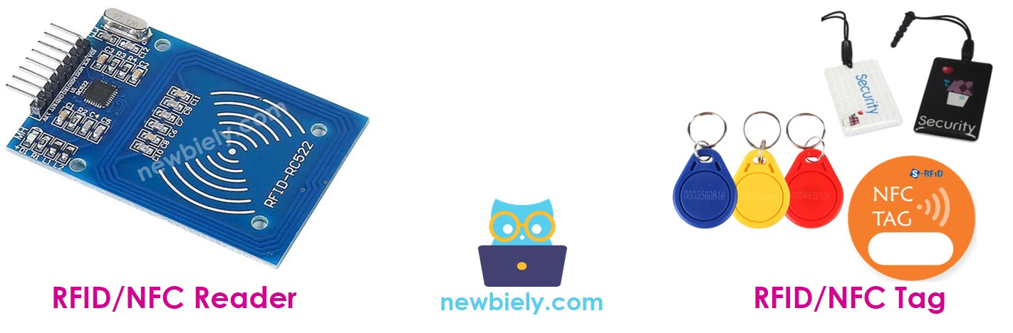
The tag only has to be close to the reader. It does not need to be in direct line of sight. A reading goes like this:
- The reader's magnetic field makes current flow in the tag's antenna, and this powers the chip.
- The chip sends its data back to the reader as a new radio signal.
- The reader picks up this signal and turns it into data.
- The ESP32 S3 Uno gets the data from the reader over SPI and processes it.
ESP32 S3 Uno Pinout
The image below shows the pinout of the ESP32 S3 Uno form board. Use it to find the Uno header pins (D5, D10 to D13, 3.3V) and their GPIO numbers when you wire the RC522 module.

Wiring Diagram between RFID-RC522 Module and ESP32 S3 Uno
The RC522 runs on 3.3V, the same as the ESP32 S3 Uno pins. Connect its VCC to the 3.3V pin, not 5V.
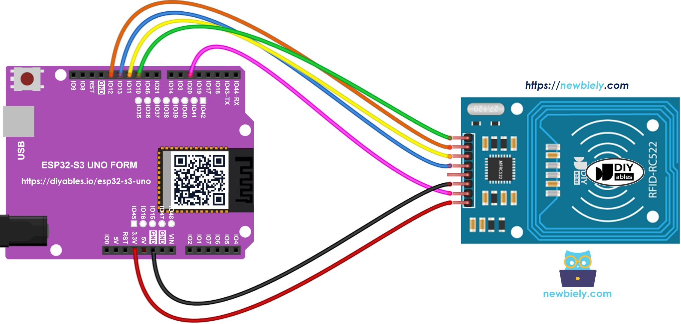
This image is created using Fritzing. Click to enlarge image
Wiring table of RFID/NFC RC522 Module and ESP32 S3 Uno
| RFID/NFC RC522 | ESP32 S3 Uno Pin |
|---|---|
| SS | D10 (GPIO10) |
| SCK | D13 (GPIO12) |
| MOSI | D11 (GPIO11) |
| MISO | D12 (GPIO13) |
| IRQ | not connected |
| GND | GND |
| RST | D5 (GPIO20) |
| VCC | 3.3V |
※ NOTE THAT:
D10 to D13 on the ESP32 S3 Uno are the default SPI pins of the chip (SS 10, MOSI 11, SCK 12, MISO 13). This is why SPI.begin() needs no pin numbers in the code.
ESP32 S3 Uno RFID/NFC Code
The sketch starts the SPI bus and the RC522 reader, then waits for a tag. When a tag comes close, it reads the UID and prints it on the Serial Monitor in hex format. After that, it stops talking to the tag so the next tap can be read.
The pin numbers in the code are GPIO numbers: SS_PIN is 10 (D10) and RST_PIN is 20 (D5). If you move a wire, change the number to the GPIO from the pinout, not the D label.
Detailed Instructions
Follow these steps in order:
- New to the ESP32 S3 Uno? Follow ESP32 S3 Uno - Getting Started first.
- Wire it up as shown in the diagram.
- Connect the board to your computer with a USB Type-C cable.
- Open Arduino IDE, choose the ESP32S3 Dev Module board and the correct COM port.
- Open the Library Manager by clicking the Libraries icon on the left side of Arduino IDE.
- Search for the library: type “MFRC522” and find the one by GithubCommunity.
- Install it by clicking the Install button.
- Search for MFRC522 created by GithubCommunity and click the Install button.
- Copy the code above and paste it into Arduino IDE.
- Upload the code by clicking the Upload button.
- Open the Serial Monitor and set it to 9600 baud.
- Tap a tag: hold an RFID/NFC card or key fob close to the RC522 module.
- Check the result: the UID of each tag appears on the Serial Monitor.
- Tip: write down the UID of each of your tags. You will need these values later if you build an RFID door lock or an access list.
A MIFARE Classic 1K card usually has a 4-byte UID, and a MIFARE Ultralight tag has a 7-byte UID. That is why the two UIDs above have different lengths.
Video Tutorial
Watch the video below to see this ESP32 S3 Uno project step by step.
FAQ
Which pins does the RC522 use on the ESP32 S3 Uno?
SCK, MOSI and MISO go to D13 (GPIO12), D11 (GPIO11) and D12 (GPIO13), which are the default SPI pins. SS goes to D10 (GPIO10) and RST goes to D5 (GPIO20). You can move SS and RST to other free pins, but then update SS_PIN and RST_PIN in the code with the GPIO number.
Does the MFRC522 library work on the ESP32 S3 Uno?
Yes. The same MFRC522 library used on the UNO R4 works on the ESP32 S3 Uno with the esp32 core by Espressif Systems. The code is the same, only the pin numbers change to GPIO numbers.
Why does nothing show when I tap a tag?
Check the wiring first, especially SS and RST. Then hold the tag flat and very close to the reader, within about 3 cm. Also make sure the tag is a 13.56 MHz MIFARE type. The RC522 cannot read 125 kHz tags.
Can I connect more than one RC522 to the ESP32 S3 Uno?
Yes. All readers can share SCK, MOSI and MISO. Each reader needs its own SS pin, and you create one MFRC522 object per reader. The RST pins can be shared or separate.
What if my project needs more pins than the Uno headers give?
The ESP32 S3 Uno has two extra rows of holes with more GPIOs: GPIO15 and GPIO16 (I/O, PWM, analog), GPIO45 and GPIO35 to GPIO42 (I/O, PWM), and GPIO47/GPIO48 (output only, PWM). Solder pin headers to use them and write the GPIO number in code. For a second RC522 reader, GPIO35 to GPIO42 are a good choice for the extra SS pin. For door lock parts like a relay or a buzzer, GPIO15 or GPIO16 work well. Two warnings: (1) GPIO47/GPIO48 may run at 1.8V instead of 3.3V on some modules (especially ones with "V" in the name, like R8V or R16V), so 3.3V devices can be damaged or act strangely; (2) GPIO0, GPIO3 (D6), GPIO45 and GPIO46 (D9) are boot strapping pins, and a wrong connection can stop the board from booting or uploading code. Use the other extra pins first.
Troubleshooting
| Problem | Possible Cause | Solution |
|---|---|---|
| No COM port in Arduino IDE | USB driver missing or board not in upload mode | Install the CP210x or CH340 driver, use a data USB cable, or hold BOOT while pressing RESET |
| Nothing appears when a tag is tapped | Wrong wiring or loose jumper wire | Check SS on D10 (GPIO10), RST on D5 (GPIO20) and the three SPI wires on D11 to D13 |
| Module gets hot or stops working | VCC connected to 5V | Move VCC to the 3.3V pin and check the module still works |
| Compile error MFRC522.h not found | Library not installed | Install the MFRC522 library by GithubCommunity from the Library Manager |
| Some tags are never read | Tag uses 125 kHz or is too far away | Use 13.56 MHz MIFARE tags and hold them within about 3 cm of the reader |
| Garbage characters on the Serial Monitor | Baud rate does not match | Set the Serial Monitor to 9600 baud |
| UID shows only once per tap | Normal behavior of the code | The tag is halted after reading. Move it away and tap again to read it once more |