
ESP32 S3 UNO - LCD I2C
This ESP32 S3 Uno LCD I2C tutorial shows you how to connect a 16x2 LCD I2C display to the ESP32 S3 Uno form board and print text on it with Arduino code. Thanks to the I2C interface, the LCD 16x2 needs only four wires. You will see your own messages, numbers and even small icons on the screen.
In this tutorial, you will:
- Wire a 16x2 LCD I2C display to the SDA and SCL pins
- Install the DIYables_LCD_I2C library in the Arduino IDE
- Display text and numbers on the LCD I2C
- Create and show custom characters on the LCD display
- Find the I2C address with an I2C scanner sketch
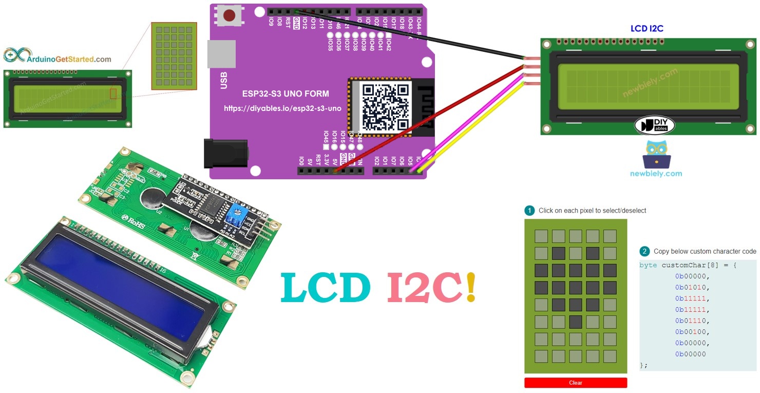
Hardware Preparation
Or you can buy the following kits:
| 1 | × | DIYables Sensor Kit (18 sensors/displays) |
Additionally, some of these links are for products from our own brand, DIYables .
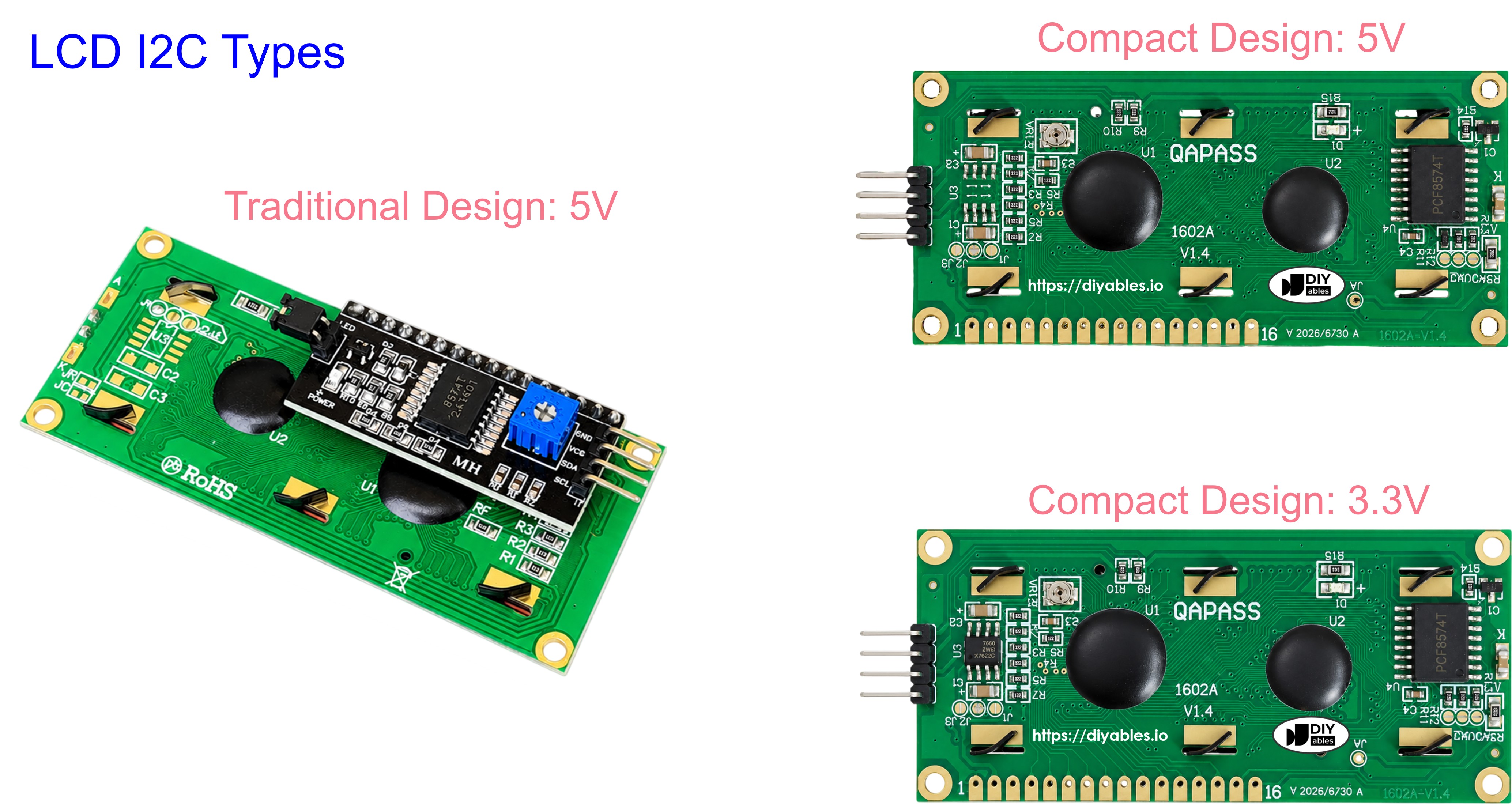
Buy Note: Most LCD I2C displays available on the market are 5V displays. They may work with this board, but it is unsafe and can damage the board. We strongly recommend using the 3.3V LCD I2C display recommended above.
Overview of LCD I2C 16x2
A plain 16x2 LCD needs many wires. The I2C version has a small backpack board on the back that cuts this down to just two signal lines. This makes it one of the easiest displays to add to an ESP32 S3 Uno project.
The screen has 16 columns and 2 rows, so it can show up to 32 characters at once. A small potentiometer on the backpack lets you set the contrast.
Pinout
The LCD I2C module has 4 pins. Two of them give power, and two carry the I2C signals.
| Pin | Function |
|---|---|
| GND | Ground (0V) |
| VCC | Power supply (5V) |
| SDA | I2C data line |
| SCL | I2C clock line |
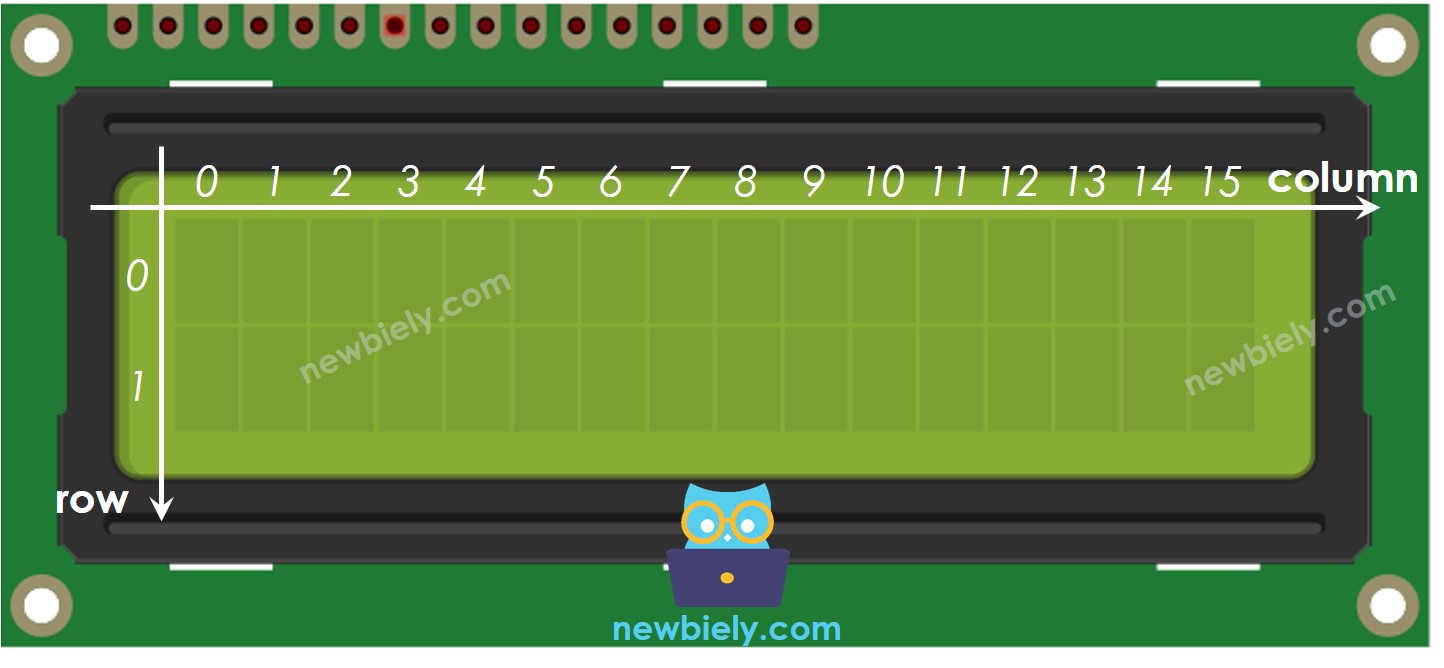
LCD Coordinate
To print in the right place, you need to know how the screen positions are numbered. The LCD 16x2 has 16 columns and 2 rows, and both the column and the row numbers start at 0. So the top-left cell is (0, 0) and the bottom-right cell is (15, 1).
ESP32 S3 Uno Pinout
The image below shows the pinout diagram of the ESP32 S3 Uno form board. Use it to find the SDA and SCL header pins and their GPIO numbers when you wire the LCD.

Wiring Diagram
The LCD takes power from the 5V pin and talks to the board over I2C. On the ESP32 S3 Uno, connect SDA and SCL to the SDA and SCL header pins, not to A4 and A5.
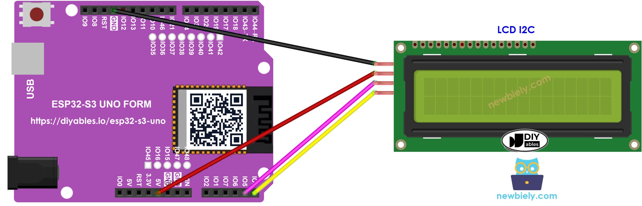
This image is created using Fritzing. Click to enlarge image
| LCD I2C Pin | ESP32 S3 Uno Pin |
|---|---|
| VCC | 5V |
| GND | GND |
| SDA | SDA (GPIO8) |
| SCL | SCL (GPIO9) |
※ NOTE THAT:
On this board, A4 and A5 are only analog pins, not I2C pins. The I2C bus is on the SDA (GPIO8) and SCL (GPIO9) header pins, and Wire.begin() uses them by default.
WARNING
The ESP32 S3 Uno pins work at 3.3V and are NOT 5V tolerant. Many LCD I2C backpacks pull SDA and SCL up to their own VCC, so with 5V power these lines can sit at 5V. To keep the board safe, pass SDA and SCL through a bidirectional 5V to 3.3V level converter, or remove the pull-up resistors on the backpack.
How To Program For LCD I2C
The DIYables_LCD_I2C library hides all the low-level I2C work. You only need a few short commands to put text on the screen. Here are the basic steps.
Include the library
Create the LCD object
Give it the I2C address, the number of columns and the number of rows.
Start the LCD
Call these two lines in setup() to start the display and turn on its backlight.
Move the cursor
Pick the column and row where the next text should start.
Print a message
The LCD can do much more than this. See the "Do More with LCD" section below.
※ NOTE THAT:
The I2C address of the LCD can be different between makers. This code uses 0x27, the address given by the manufacturer DIYables.
ESP32 S3 Uno Code
This sketch starts the LCD, turns on the backlight and prints two lines of text. "DIYables" appears on the first row from column 3, and "www.diyables.io" appears on the second row. All the work happens in setup(), so loop() stays empty.
Detailed Instructions
- New to the ESP32 S3 Uno? Follow ESP32 S3 Uno - Getting Started first.
- Wire it up as shown in the diagram, with SDA and SCL on the SDA and SCL header pins.
- Connect the board to your computer with a USB Type-C cable.
- Open Arduino IDE, choose the ESP32S3 Dev Module board and the correct COM port.
- Open the Library Manager by clicking the Libraries icon on the left side of the Arduino IDE.
- Search for DIYables LCD I2C and find the DIYables_LCD_I2C library by DIYables.
- Install the library by clicking the Install button.
- Search for DIYables LCD I2C created by DIYables.io and click the Install button.
- Copy the code above and paste it into the Arduino IDE.
- Upload the code by clicking the Upload button.
- Check the LCD. You should see the two lines of text on the screen.
- Tip: change the text and the cursor position in the code, then upload again to see how the layout changes.
Video Tutorial
Watch the video below to see this ESP32 S3 Uno project step by step.
Do More with LCD
Once basic text works, you can draw your own symbols and control the cursor. The parts below show you how.
Custom Character
The lcd.print() function can only show standard ASCII characters. To show a symbol like a heart or a small arrow, you need to design a custom character.
The LCD 16x2 has 32 character cells, 16 on each row. Every cell is a grid of 40 small dots: 8 rows and 5 columns. A custom character tells the LCD which of these dots to turn on.
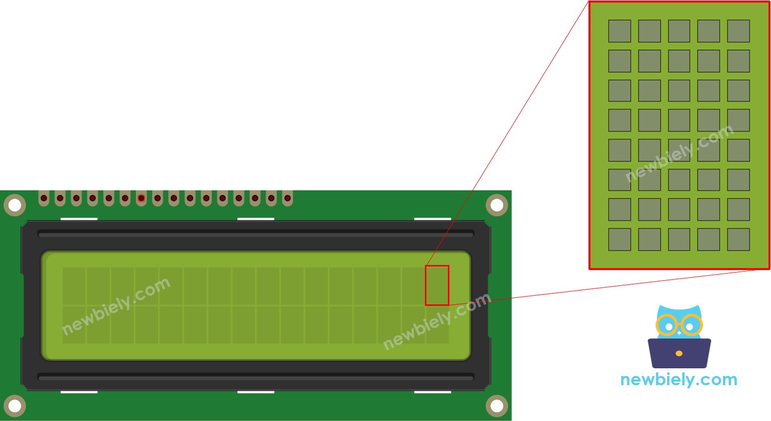
Use the character generator below to design your 40-dot character. Just follow the steps:
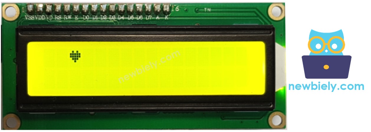
This is what you see on the screen:
Multiple custom characters
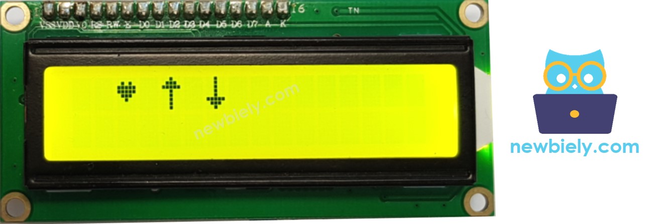
The LCD can store up to 8 custom characters, with index numbers 0 to 7. The sketch below creates three of them, a heart, an up arrow and a down arrow, and shows them side by side.
The result on the LCD display:
Summary: how to use a custom character on the LCD
- Design your symbol with the character generator above.
- Copy the binary code it gives you into your sketch.
- In setup(), register the character under an index from 0 to 7.
- Show the character wherever you need it, in setup() or in loop().
Other functions
The library has more handy functions. Try them one at a time: put each one in loop() and add delay(5000) after it, so you have time to see the effect.
Clear the screen
Move the cursor to the top-left corner
Move the cursor to a given column and row
Show the cursor
Hide the cursor
Make the cursor blink
Stop the cursor blinking
You can find more details in the LiquidCrystal Library Reference.
Troubleshooting on LCD I2C
When the LCD stays blank, the cause is almost always the contrast or the I2C address. Check these two things first:
- Turn the small potentiometer on the back of the LCD to change the contrast.
- Check the I2C address. It depends on the maker and is usually 0x27 or 0x3F. Try each one in the code. If neither works, upload the scanner sketch below to find the real address.
Open the Serial Monitor at 9600 baud. The output looks like this:
FAQ
Why is the LCD wired to SDA and SCL and not to A4 and A5?
On the UNO R4, A4 and A5 double as I2C pins, but on the ESP32 S3 Uno they are only analog pins. The I2C bus is on the SDA (GPIO8) and SCL (GPIO9) header pins. Wire.begin() uses these pins by default, so the code needs no pin numbers.
Can I power the LCD I2C from 3.3V on the ESP32 S3 Uno?
Most 16x2 LCD I2C modules are made for 5V. At 3.3V the text is often very faint or not visible at all. Power the LCD from 5V, and use a level converter on SDA and SCL to keep the 5V pull-ups away from the board's 3.3V pins.
Does the DIYables_LCD_I2C library work on the ESP32 S3 Uno?
Yes. The library uses the standard Wire library, which works on the ESP32 S3 Uno. The same code runs on the UNO R4 and on the ESP32 S3 Uno without any change.
How do I show a number or a sensor value on the LCD?
Pass the value to lcd.print(), for example lcd.print(temperature);. Call lcd.clear() or print spaces first, so old digits do not stay on the screen when the number gets shorter.
Can I connect two LCD I2C displays to one ESP32 S3 Uno?
Yes, if they have different I2C addresses. Many backpacks have A0, A1 and A2 solder pads to change the address. Create two DIYables_LCD_I2C objects, one for each address, and wire both LCDs to the same SDA and SCL pins.
What if my project needs more pins than the Uno headers give?
The ESP32 S3 Uno has two extra rows of holes with more GPIOs: GPIO15 and GPIO16 (I/O, PWM, analog), GPIO45 and GPIO35 to GPIO42 (I/O, PWM), and GPIO47/GPIO48 (output only, PWM). Solder pin headers to them and write the GPIO number in code. The LCD only uses the I2C pins, so the extra pins are free for buttons or sensors. Use GPIO15/GPIO16 for analog sensors and GPIO35 to GPIO42 for buttons. Do not use GPIO47/GPIO48 for inputs, because they are output only. Be careful with two things. First, GPIO47/GPIO48 may run at 1.8V instead of 3.3V on some modules (especially ones with "V" in the name, like R8V or R16V), so 3.3V devices can be damaged or act strangely. Second, GPIO0, GPIO3 (D6), GPIO45 and GPIO46 (D9) are boot strapping pins, and a wrong connection can stop the board from booting or uploading code. Use the other extra pins first.
Troubleshooting
| Problem | Possible Cause | Solution |
|---|---|---|
| No COM port in Arduino IDE | USB driver missing or bad cable | Install the CP210x or CH340 driver, try a data USB cable, or hold BOOT while pressing RESET |
| LCD shows nothing at all | LCD not powered or SDA/SCL on A4/A5 | Power the LCD from 5V and move SDA and SCL to the SDA (GPIO8) and SCL (GPIO9) header pins |
| Backlight is on but no text | Contrast too low or wrong I2C address | Turn the contrast screw on the back and run the I2C scanner to find the address (often 0x27 or 0x3F) |
| Top row shows only white blocks | LCD not started or wrong address in code | Make sure lcd.init() runs in setup() and the address in the code matches the scanner result |
| Scanner prints No I2C devices found | SDA and SCL swapped or loose wires | Check that SDA goes to SDA (GPIO8) and SCL goes to SCL (GPIO9), and press the wires in firmly |
| Text is faint or flickers | LCD powered from 3.3V or weak USB power | Power the LCD from the 5V pin and use a good USB cable |
| Compile error about DIYables_LCD_I2C.h | Library not installed | Install the DIYables_LCD_I2C library from the Library Manager |
| Custom character shows wrong symbol | Index used in write() does not match createChar() | Use the same index from 0 to 7 in lcd.createChar() and lcd.write((byte)index) |