
ESP32 S3 UNO - Blink multiple LED
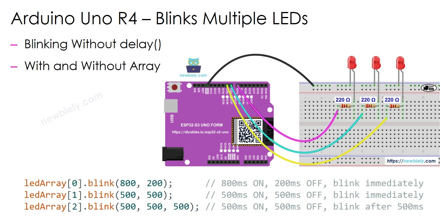
This ESP32 S3 Uno blink multiple LED tutorial shows you how to make several LEDs blink at different speeds at the same time on the ESP32 S3 Uno form board. You will not use the delay() function, so every LED keeps its own rhythm. The example uses three LEDs, but you can easily change it to blink two LEDs, four LEDs or more.
In this tutorial, you will:
- Wire three LEDs to the ESP32 S3 Uno
- Blink multiple LEDs at different speeds without delay()
- Install and use the ezLED library in the Arduino IDE
- Manage an array of LEDs with a simple for loop
Hardware Preparation
Or you can buy the following kits:
| 1 | × | DIYables Sensor Kit (18 sensors/displays) |
Additionally, some of these links are for products from our own brand, DIYables .
Buy Note: Use the LED Module for easier wiring. It includes an integrated resistor.
Overview of LED
This project builds on the single LED basics. If you have not used an LED before, learn how it works first, because each LED here is wired the same way.
The LED tutorial explains the LED pins, how it lights up, how to wire it with a resistor and how to control it with code on the ESP32 S3 Uno. You can read it here: ESP32 S3 Uno - LED tutorial.
※ NOTE THAT:
You need one LED and one 220 ohm resistor for each LED you want to blink. For this example, that means three LEDs and three resistors.
ESP32 S3 Uno Pinout
The image below shows the pinout diagram of the ESP32 S3 Uno form board. Use it to find the Uno header pins (D7, D8, D9…) and their GPIO numbers when you wire the LEDs.

Wiring Diagram
Each LED connects to its own pin through a 220 ohm resistor, and all LED cathodes go to GND.
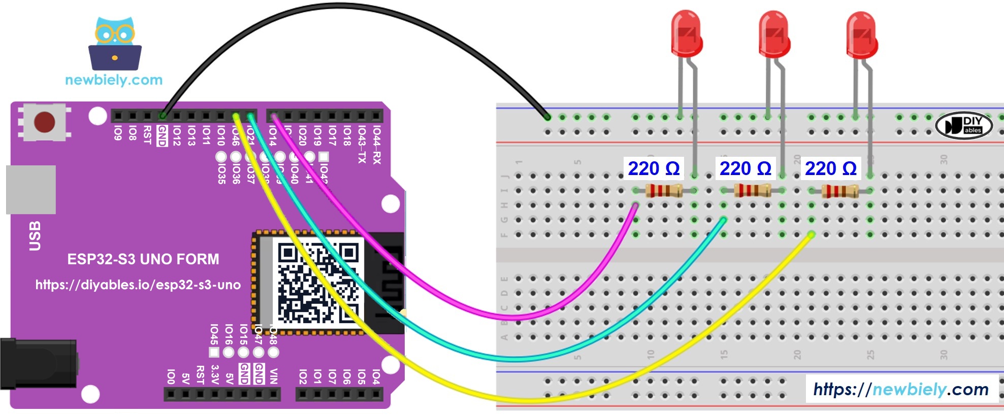
This image is created using Fritzing. Click to enlarge image
| Component Pin | ESP32 S3 Uno Pin |
|---|---|
| LED 1 anode (+) through 220 ohm resistor | D7 (GPIO14) |
| LED 2 anode (+) through 220 ohm resistor | D8 (GPIO21) |
| LED 3 anode (+) through 220 ohm resistor | D9 (GPIO46) |
| LED 1, 2, 3 cathode (-) | GND |
WARNING
LED 3 uses D9 (GPIO46). This is a boot strapping pin on the ESP32 S3 Uno. The chip reads it at startup to pick the boot mode. An LED with a 220 ohm resistor to GND is normally fine, but if the board does not boot or upload, unplug the wire from D9 first, upload the code, then plug it back in.
※ NOTE THAT:
The ESP32 S3 Uno pins work at 3.3V, not 5V. A 220 ohm resistor still works well, the LEDs are just a little less bright than on a 5V board.
ESP32 S3 Uno Code - Blink Multiple LEDs
If you blink LEDs with delay(), the board stops and waits. While it waits, nothing else runs, so you cannot blink several LEDs at different speeds. The fix is to check the time with millis() and switch each LED only when its own time is up.
Keeping a timestamp for every LED is hard for beginners. The ezLED library does this work for you inside the library, so your code stays short and easy to read.
The sketch creates one ezLED object for each pin. In setup(), each LED gets its own ON time, OFF time and optional start delay. In loop(), you must call loop() on every LED object, because this is where the library checks the time and switches the LED.
Detailed Instructions
Follow these steps one by one:
- New to the ESP32 S3 Uno? Follow ESP32 S3 Uno - Getting Started first.
- Wire it up as shown in the diagram.
- Connect the board to your computer with a USB Type-C cable.
- Open Arduino IDE, choose the ESP32S3 Dev Module board and the correct COM port.
- Open the Library Manager by clicking the Libraries icon on the left side of the Arduino IDE.
- Search for "ezLED" and find the LED library by ArduinoGetStarted.
- Install the library by clicking the Install button.
- Search for ezLED created by ArduinoGetStarted.com and click the Install button.
- Copy the code above and paste it into the Arduino IDE.
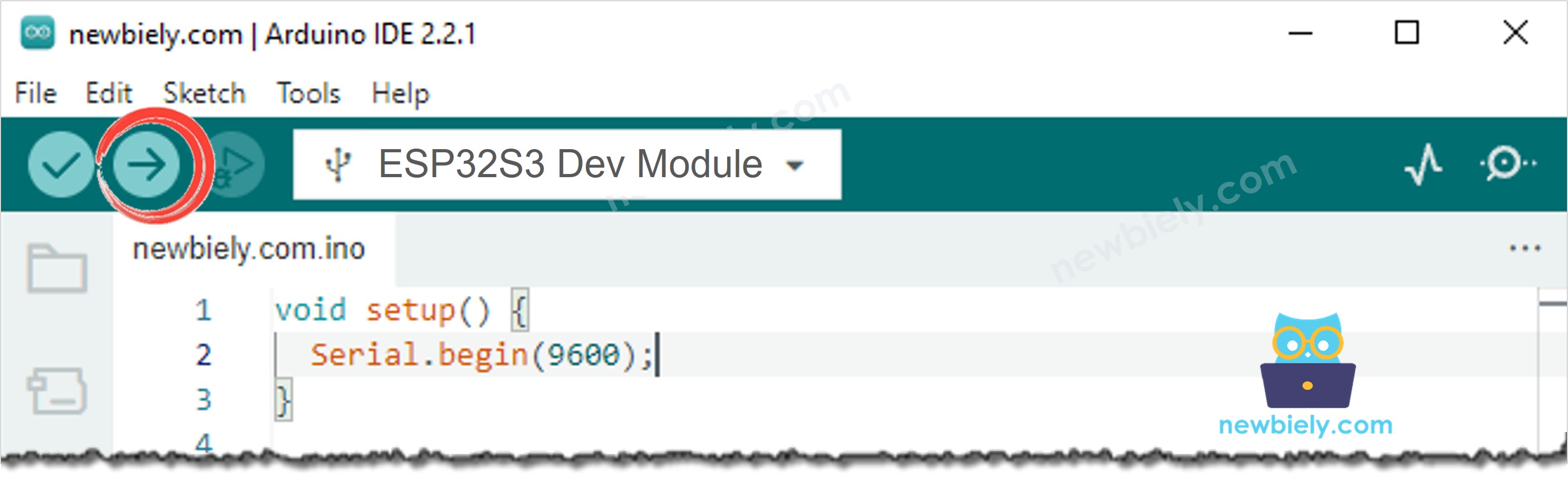
- Upload the code by clicking the Upload button.
- Watch the LEDs. LED 1 stays on longer than it stays off, LED 2 blinks evenly, and LED 3 starts blinking half a second later.
- Tip: Change the numbers in blink() to give each LED a different speed, then upload again to see the result.
ESP32 S3 Uno Code - Blink Multiple LEDs by using array
When you add more LEDs, the code above gets long because every LED needs its own lines. An array of LED objects fixes this. You keep all LEDs in one list and handle them with a single for loop.
This version stores the three ezLED objects in ledArray. The setup part is the same as before, and loop() uses a for loop to call loop() on every LED. To blink four LEDs, change NUM_LED to 4 and add one more pin and one more object to the array.
More things you can do with ezLED
The ezLED library gives you a lot of control over many LEDs at once. You can make each LED blink at its own speed, start blinking at a different time, blink only for a set period, or blink a set number of times. The example sketches that come with the library show how to do each of these.
Video Tutorial
Watch the video below to see this ESP32 S3 Uno project step by step.
FAQ
Can I blink multiple LEDs on the ESP32 S3 Uno without delay()?
Yes. Use millis() to check the time, or use the ezLED library, which does the timing for you. With delay(), the board stops and waits, so the LEDs cannot blink at different speeds.
Which pins can I use for LEDs on the ESP32 S3 Uno?
Almost any Uno header pin works, because they all support digital output and PWM. Good choices are D2 (GPIO18), D3 (GPIO17), D4 (GPIO19), D5 (GPIO20), D7 (GPIO14) and D8 (GPIO21). In code, always write the GPIO number, not the D label. Avoid D0 and D1, because they are used for USB serial.
Do I need a different resistor on the ESP32 S3 Uno than on a 5V Arduino?
No. A 220 ohm resistor works fine. The ESP32 S3 Uno pins give 3.3V, so the current is a bit lower and the LED is a little dimmer. Do not connect an LED without a resistor, because it can damage the pin.
Why does my board not boot when an LED is on D9?
D9 is GPIO46 on the ESP32 S3 Uno, which is a boot strapping pin. The chip reads it at startup. A plain LED with a resistor to GND usually does not cause a problem, but if the board does not start or upload, unplug D9 while you upload, or move the LED to a free pin and change the pin number in code.
What if I want to blink more LEDs than the Uno headers give?
The ESP32 S3 Uno has two extra rows of holes with more GPIOs: GPIO15 and GPIO16 (I/O, PWM, analog), GPIO45 and GPIO35 to GPIO42 (I/O, PWM), and GPIO47/GPIO48 (output only, PWM). Solder pin headers to use them and write the GPIO number in code. For extra LEDs, GPIO35 to GPIO42, GPIO15 and GPIO16 are the best choice. Be careful with two things. First, GPIO47 and GPIO48 may run at 1.8V instead of 3.3V on some modules (especially ones with "V" in the name, like R8V or R16V), so 3.3V devices can be damaged or act strangely. Second, GPIO0, GPIO3 (D6), GPIO45 and GPIO46 (D9) are boot strapping pins, and a wrong connection can stop the board from booting or uploading code. Use the other extra pins first.
Does the ezLED library work on the ESP32 S3 Uno?
Yes. The ezLED library only uses standard Arduino functions like digitalWrite() and millis(), so it works on the ESP32 S3 Uno just like on other Arduino boards.
Troubleshooting
| Problem | Possible Cause | Solution |
|---|---|---|
| No COM port in the Arduino IDE | USB driver missing or charge-only cable | Install the CP210x or CH340 driver, use a data USB cable, or hold BOOT while pressing RESET |
| Upload fails or board does not start | LED circuit on D9 (GPIO46) affects the boot strapping pin | Unplug the D9 wire while uploading, then plug it back in |
| One LED never lights up | LED is in backwards or the wire is loose | Put the long leg (anode) toward the resistor and pin, and check every jumper wire |
| All LEDs stay off | Common GND wire is missing | Connect all LED cathodes to a GND pin of the ESP32 S3 Uno |
| Compile error ezLED.h not found | ezLED library is not installed | Install ezLED from the Library Manager |
| LEDs blink once and then stop | The loop() function of an LED object is not called | Call loop() for every LED object inside loop() |
| LEDs are very dim | Resistor value is too high | Use a 220 ohm resistor, the pins only give 3.3V |