
ESP32 S3 UNO - DHT11 - LCD
This ESP32 S3 Uno DHT11 LCD tutorial shows you how to build a small room monitor: the ESP32 S3 Uno form board reads a DHT11 temperature and humidity sensor and prints both values on a 16x2 LCD I2C display. The screen updates every two seconds, so you can watch the numbers change when the air gets warmer or cooler.
In this tutorial, you will:
- Wire a DHT11 module and an LCD I2C display to the ESP32 S3 Uno.
- Install the DHT sensor library and the DIYables LCD I2C library in Arduino IDE.
- Read temperature and humidity with readTemperature() and readHumidity().
- Show the values on the LCD display, including the degree sign.
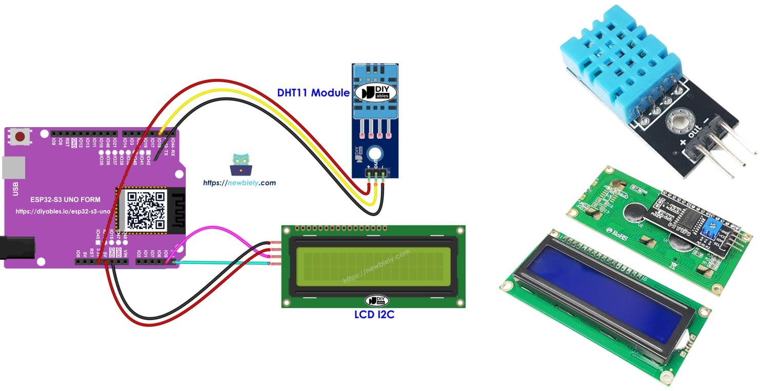
Hardware Preparation
Or you can buy the following kits:
| 1 | × | DIYables Sensor Kit (18 sensors/displays) |
Additionally, some of these links are for products from our own brand, DIYables .
Buy Note: Most LCD I2C displays available on the market are 5V displays. They may work with this board, but it is unsafe and can damage the board. We strongly recommend using the 3.3V LCD I2C display recommended above.
Overview of DHT11 and LCD
This project joins two parts you may already know. If you want the details of each one first, like the pinout and the basic code, read these tutorials:
ESP32 S3 Uno Pinout
The image below shows the pinout of the ESP32 S3 Uno form board. Use it to find the D2, SDA and SCL header pins and their GPIO numbers while you wire the circuit.

Wiring Diagram
The DHT11 DATA pin goes to D2, and the LCD goes to the SDA and SCL header pins. Follow the diagram and the table below.
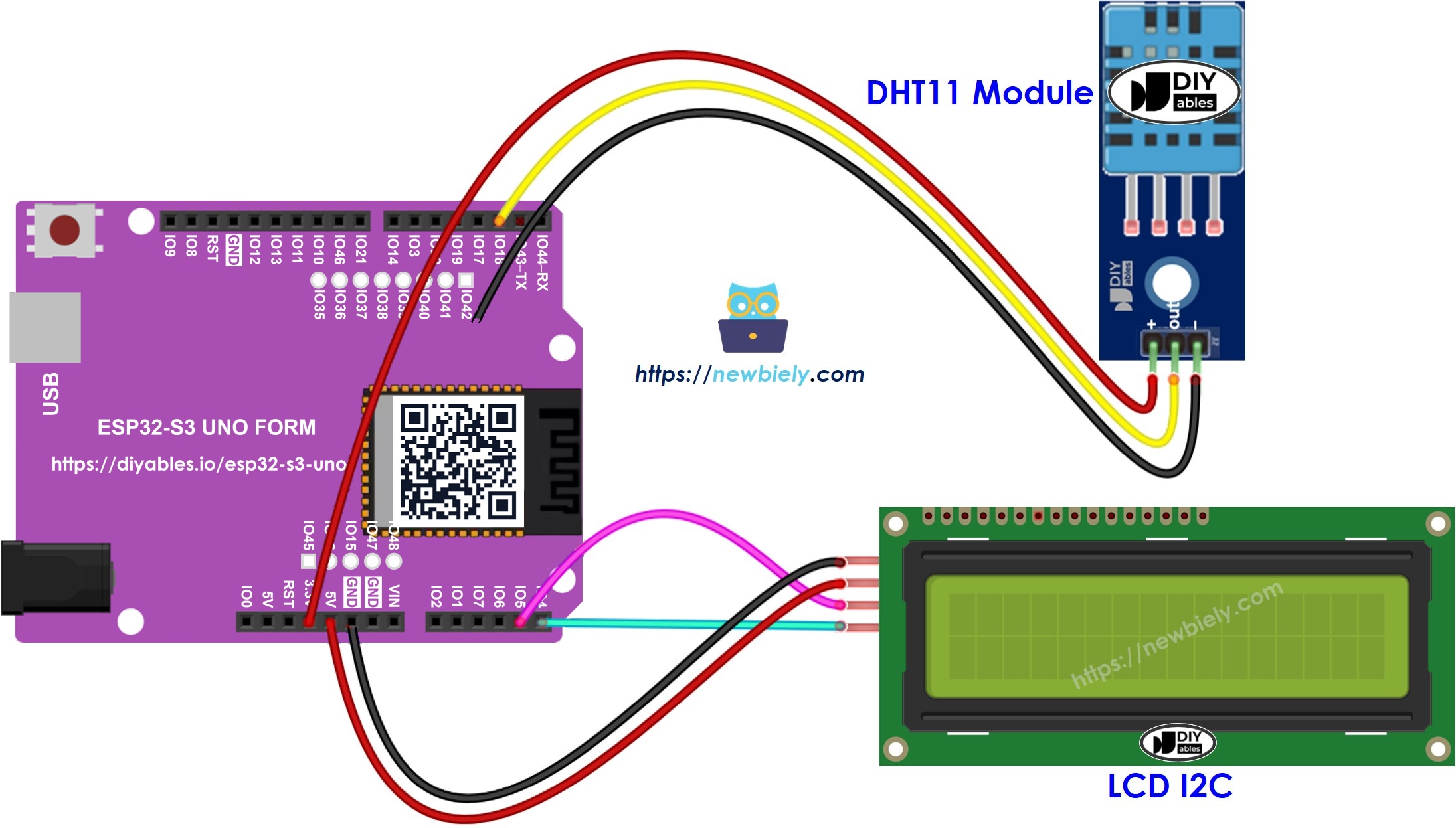
This image is created using Fritzing. Click to enlarge image
| Component Pin | ESP32 S3 Uno Pin |
|---|---|
| DHT11 VCC (+) | 3.3V |
| DHT11 GND (-) | GND |
| DHT11 DATA (OUT) | D2 (GPIO18) |
| LCD VCC | 5V |
| LCD GND | GND |
| LCD SDA | SDA (GPIO8) |
| LCD SCL | SCL (GPIO9) |
The DHT11 module already has a pull-up resistor on its DATA line. If you use the bare 4-pin DHT11 sensor, add a 10 kΩ resistor between DATA and 3.3V.
WARNING
The ESP32 S3 Uno pins work at 3.3V and are NOT 5V tolerant. Power the DHT11 from 3.3V, so its pull-up keeps the DATA line at 3.3V. Many LCD I2C backpacks pull SDA and SCL up to their own 5V supply. To keep the board safe, pass SDA and SCL through a bidirectional 5V to 3.3V level converter, or remove the pull-up resistors on the LCD backpack.
※ NOTE THAT:
On the ESP32 S3 Uno, A4 and A5 are NOT I2C pins. Always wire the LCD to the SDA and SCL header pins.
ESP32 S3 Uno Code - DHT11 Sensor - LCD I2C
The sketch reads the DHT11 every two seconds. It prints the temperature in °C on the first LCD row and the humidity on the second row. If the reading fails, the LCD shows "Failed", so you know to check the sensor wiring. The DHT11 data pin is set to 18, which is the D2 header pin.
※ NOTE THAT:
The I2C address of an LCD can be different from one maker to another. The code uses 0x27, which is the address of the DIYables LCD. If your screen stays empty, scan for the address and change it in the code.
Detailed Instructions
Do these steps in order:
- New to the ESP32 S3 Uno? Follow ESP32 S3 Uno - Getting Started first.
- Wire it up as shown in the diagram.
- Connect the board to your computer with a USB Type-C cable.
- Open Arduino IDE, choose the ESP32S3 Dev Module board and the correct COM port.
- Open the Library Manager by clicking the Libraries icon on the left side of Arduino IDE.
- Install the DHT library: search for "DHT", find the DHT sensor library by Adafruit and click Install.
- Search for DHT sensor library created by Adafruit and click the Install button.
- Install the dependencies: Arduino IDE asks for extra libraries. Click Install All.
- Install the LCD library: search for "DIYables LCD I2C", find the DIYables_LCD_I2C library by DIYables and click Install.
- Search for DIYables LCD I2C created by DIYables.io and click the Install button.
- Copy the code above and paste it into Arduino IDE.
- Upload the code by clicking the Upload button.
- Test it: make the air around the sensor warmer or cooler, for example by holding the sensor in your hand.
- Look at the LCD: the first row shows the temperature and the second row shows the humidity. The values change after a few seconds.
- Tip: the DHT11 needs about one second between readings. Do not make the delay in the loop shorter than that, or you will see "Failed" on the LCD.
If the LCD shows nothing, read the Troubleshooting for LCD I2C.
Video Tutorial
Watch the video below to see this ESP32 S3 Uno project step by step.
FAQ
Should I power the DHT11 from 3.3V or 5V on the ESP32 S3 Uno?
Use 3.3V. The DHT11 works from 3V to 5V, and at 3.3V its DATA line stays at a safe level. The ESP32 S3 Uno pins are not 5V tolerant, so a 5V pull-up on DATA can damage GPIO18.
Why is the LCD wired to SDA and SCL and not to A4 and A5?
On the UNO R4, A4 and A5 are the I2C pins. On the ESP32 S3 Uno they are only analog pins. I2C is on the separate SDA (GPIO8) and SCL (GPIO9) header pins, and Wire.begin() uses them by default.
Why does the LCD show "Failed"?
The code shows "Failed" when the DHT library gets no valid data from the sensor. Usually the DATA wire is loose or on the wrong pin, the sensor has no power, or the bare sensor has no pull-up resistor.
Can I show the temperature in Fahrenheit on the LCD?
Yes. Use dht11.readTemperature(true) to get °F, and print "F" instead of "C". The 16x2 LCD has room for only two short lines, so pick one unit, or show °C and °F one after the other.
Can I use another pin for the DHT11?
Yes. Most digital pins work. Change DHT11_PIN to the GPIO number, not the D label. For example, D7 is 14. Avoid D6 (GPIO3) and D9 (GPIO46), because they are boot strapping pins.
What if my project needs more pins than the Uno headers give?
The ESP32 S3 Uno has two extra rows of holes with more GPIOs. GPIO15 and GPIO16 support I/O, PWM and analog. GPIO45 and GPIO35 to GPIO42 support I/O and PWM. GPIO47 and GPIO48 are output only, with PWM. Solder pin headers to use them and write the GPIO number in code. For a second DHT11 or a button, GPIO35 to GPIO42 are a good choice. Do not use GPIO47/GPIO48 for sensors or inputs. Be careful with two things. First, GPIO47 and GPIO48 may run at 1.8V instead of 3.3V on some modules (especially ones with "V" in the name, like R8V or R16V), so 3.3V devices can be damaged or act strangely. Second, GPIO0, GPIO3 (D6), GPIO45 and GPIO46 (D9) are boot strapping pins, and a wrong connection can stop the board from booting or uploading code. Use the other extra pins first.
Troubleshooting
| Problem | Possible Cause | Solution |
|---|---|---|
| No COM port in Arduino IDE | USB driver is missing or the board is not in upload mode | Install the CP210x or CH340 driver, or hold BOOT while pressing RESET |
| LCD shows nothing at all | LCD not powered, or SDA/SCL wired to A4/A5 | Power the LCD from 5V and wire SDA and SCL to the SDA (GPIO8) and SCL (GPIO9) header pins |
| LCD backlight is on but there is no text | Wrong I2C address or low contrast | Run an I2C scanner, set the right address in the code, and turn the contrast screw on the backpack |
| LCD shows "Failed" | The board gets no data from the DHT11 | Check the DATA wire on D2 (GPIO18), the power wires, and the pull-up resistor on a bare sensor |
| Compile error about DHT.h or DIYables_LCD_I2C.h | A library is not installed | Install the DHT sensor library, Adafruit Unified Sensor and DIYables_LCD_I2C from the Library Manager |
| Values change very slowly or in big steps | This is normal for the DHT11 | The DHT11 shows whole numbers only. Use a DHT22 for more precision |
| Temperature reads too high | The sensor is close to the board or the LCD, which get warm | Keep the sensor a few centimeters away from the board and the LCD |