
ESP32 S3 UNO - LCD Keypad Shield
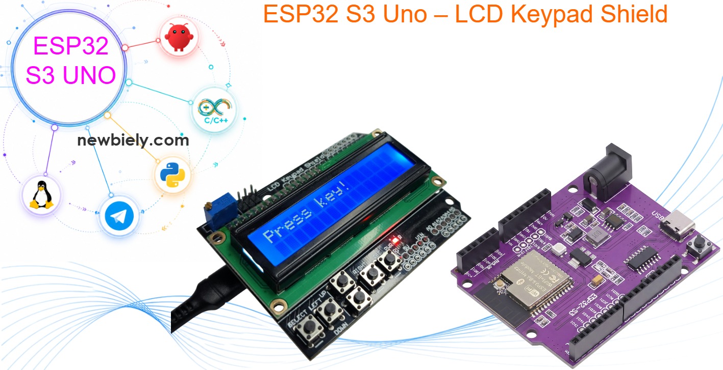
This ESP32 S3 Uno LCD Keypad Shield tutorial shows you how to stack the shield on the ESP32 S3 Uno form board and program it with Arduino code. The shield puts a 16x2 LCD and a 5-button keypad on one board. You press a button, and the LCD shows its name. You also learn one small, important fix that keeps the 3.3V analog pin safe from the shield's 5V button signal.
In this tutorial, you will:
- Learn how the LCD keypad shield works and which pins it uses
- Add one resistor so the 5V button ladder is safe for a 3.3V pin
- Show text on the 16x2 LCD with the LiquidCrystal library
- Read all 5 buttons from one analog pin with analogRead()
- Build a menu project with the keypad shield, a servo, LEDs and a DHT11
Hardware Preparation
| 1 | × | ESP32 S3 Uno-form Board | |
| 1 | × | USB Cable Type-A to Type-C (for USB-A PC) | |
| 1 | × | USB Cable Type-C to Type-C (for USB-C PC) | |
| 1 | × | LCD Keypad Shield | |
| 1 | × | 3.3 kΩ Resistor (protects the A0 pin from 5V) |
Or you can buy the following kits:
| 1 | × | DIYables Sensor Kit (18 sensors/displays) |
Additionally, some of these links are for products from our own brand, DIYables .
What’s the LCD Keypad Shield?
The LCD keypad shield gives your project a screen and buttons with no loose wires. Knowing what is on the board helps you understand the code and the one fix this board needs.
16x2 LCD
The screen shows 2 rows of 16 characters. It is a classic HD44780 type LCD, so the LiquidCrystal library drives it in 4-bit mode.
Five buttons on one pin
The Up, Down, Left, Right and Select buttons all share the A0 pin. Each button connects a different resistor, so each one gives a different voltage. The code reads that voltage and works out which button you pressed.
Reset button
The sixth button is wired to the board's RST pin. It restarts the ESP32 S3 Uno. The code cannot read it.
Contrast knob
The small blue potentiometer sets the LCD contrast. Turn it if the text is too faint or the screen is all dark boxes.
Pinout
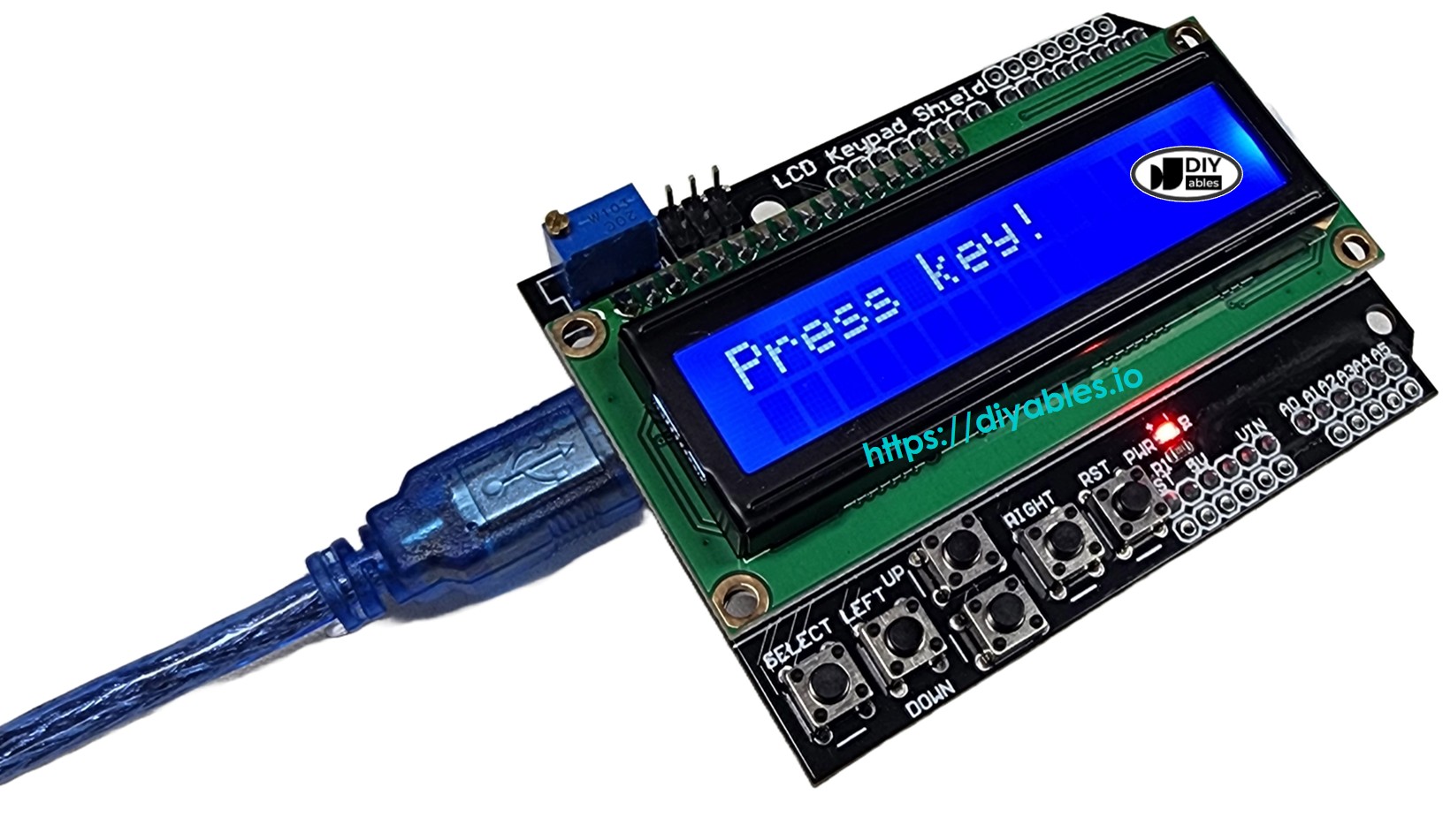
When you stack the shield, it uses the same Uno header positions as on any Uno board. The table shows where each shield pin lands and its GPIO number on the ESP32 S3 Uno.
| Shield Pin | Function | ESP32 S3 Uno Pin |
|---|---|---|
| DB4 | Data | D4 (GPIO19) |
| DB5 | Data | D5 (GPIO20) |
| DB6 | Data | D6 (GPIO3) |
| DB7 | Data | D7 (GPIO14) |
| RS | Register Select | D8 (GPIO21) |
| E | Enable | D9 (GPIO46) |
| Analog A0 | Button Input | A0 (GPIO2) |
The shield powers the LCD and the button ladder from the 5V pin. The LCD pins only receive signals from the board, and a 3.3V HIGH is enough for this LCD. The A0 button pin is different. It sends a voltage INTO the board, and that voltage can reach 5V. The wiring part below shows how to fix this.
※ NOTE THAT:
On many LCD keypad shields, D10 controls the backlight through a transistor. Do not set D10 (GPIO10) as an OUTPUT and drive it HIGH. On some shields this can overload the pin. The code in this tutorial does not use D10.
ESP32 S3 Uno Pinout
The image below shows the pinout diagram of the ESP32 S3 Uno form board. Use it to find the Uno header pins (D4 to D9, A0) and their GPIO numbers.

Wiring Diagram
The ESP32 S3 Uno has the Uno shape, so the shield plugs straight onto its headers. There is no wiring to do, but you must add one resistor first.
This image is created using Fritzing. Click to enlarge image
| Shield Pin | ESP32 S3 Uno Pin |
|---|---|
| 5V | 5V |
| GND | GND |
| DB4 | D4 (GPIO19) |
| DB5 | D5 (GPIO20) |
| DB6 | D6 (GPIO3) |
| DB7 | D7 (GPIO14) |
| RS | D8 (GPIO21) |
| E | D9 (GPIO46) |
| Buttons | A0 (GPIO2) + 3.3 kΩ resistor from A0 to GND |
WARNING
The button circuit on the shield uses a 2 kΩ pull-up to 5V. When no button is pressed, the A0 pin sits at 5V, and the Select button gives about 3.6V. The ESP32 S3 Uno pins are NOT 5V tolerant, so this can damage the A0 (GPIO2) pin over time. Before you stack the shield, solder a 3.3 kΩ resistor between the A0 pin and a GND pin on the bottom side of the shield. With this resistor, the highest voltage on A0 drops to about 3.1V, and all five buttons stay inside the 0 to 3.3V range. Do not run the shield without it.
WARNING
The LCD uses two boot strapping pins of the ESP32 S3 Uno. D6 is GPIO3 and D9 is GPIO46 (the LCD Enable pin). The board reads these pins at power-up. The LCD normally does not block booting, but if the board does not start or cannot upload code, remove the shield, upload the code, and then stack it again.
ESP32 S3 Uno Code
This sketch prints "Hello!" for 3 seconds. Then it reads A0 every 200 ms and shows the name of the pressed button on the LCD. The button thresholds are set for the 0 to 4095 range of the ESP32 S3 Uno ADC and for the 3.3 kΩ resistor fix.
The code calls analogSetAttenuation(ADC_11db) in setup(). By default, the ESP32 S3 Uno ADC can only measure a small voltage. The 11 dB setting lets the A0 pin read the full range, from 0V up to about 3.3V. Without it, the reading hits 4095 too early, and Left, Select and "no button" all look the same.
※ NOTE THAT:
Shields from different makers use slightly different resistors. If a button shows the wrong name, remove the // in front of Serial.println(key);, open the Serial Monitor, press each button and note its value. Then move the thresholds in the code so each one sits halfway between two buttons.
Detailed Instructions
- New to the ESP32 S3 Uno? Follow ESP32 S3 Uno - Getting Started first.
- Add the resistor. Solder a 3.3 kΩ resistor between A0 and GND on the bottom of the shield.
- Stack the shield on the ESP32 S3 Uno. Check that every pin sits in the right header hole.
- Connect the board to your computer with a USB Type-C cable.
- Open Arduino IDE, choose the ESP32S3 Dev Module board and the correct COM port.
- Copy the code above and paste it into the Arduino IDE. The LiquidCrystal library comes with the Arduino IDE. If it is missing, install LiquidCrystal from the Library Manager.
- Upload the code by clicking the Upload button.
- Press the buttons one at a time.
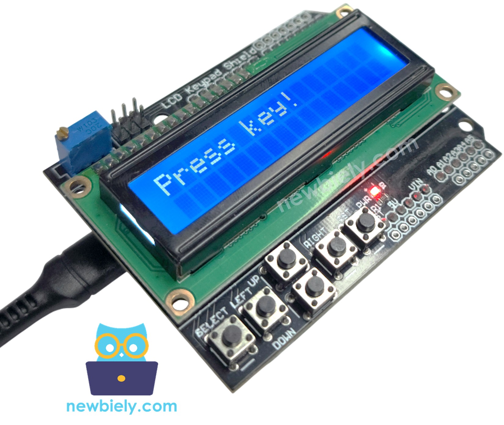
- Watch the LCD. It shows RIGHT, UP, DOWN, LEFT or SELECT. With no button pressed, it shows "Press key!".
- Tip: if a button gives the wrong name, print the A0 value to the Serial Monitor and tune the thresholds as the note above explains.
Blank screen? Check these first:
- Make sure the shield is pressed fully onto the headers.
- Turn the contrast knob slowly from one end to the other.
- Check that the code uploaded and the board has power.
Bonus: Cleaner Code
A good next step is to move the button reading into its own function. This version has a getKey() function that returns a key constant, and loop() uses a switch to print the name. The thresholds are the same as in the first sketch, so you can reuse this function in bigger projects.
Video Tutorial
Watch the video below to see this ESP32 S3 Uno project step by step.
The demo in the video is a small "smart control station". You move through menus with the keypad, read temperature and humidity from a DHT11, turn a servo and switch three LEDs. It also has an auto mode that picks the LED color and servo angle from the temperature.
| Part | ESP32 S3 Uno Pin |
|---|---|
| DHT11 DATA | D2 (GPIO18) |
| Servo signal | D3 (GPIO17) |
| Red LED | D11 (GPIO11) |
| Yellow LED | D12 (GPIO13) |
| Green LED | D13 (GPIO12) |
※ NOTE THAT:
Power the DHT11 module from 3.3V, so its data line never goes above 3.3V. The servo can run from 5V, because its signal wire only goes OUT of the board. The servo code uses the ESP32Servo library by Kevin Harrington, and the DHT11 code uses the DHT sensor library by Adafruit. Install both from the Library Manager.
Extra Help
Want to do more with the LCD? The Arduino LiquidCrystal LCD tutorial shows more ways to print text, move the cursor and make custom characters. The same LiquidCrystal functions work on the ESP32 S3 Uno.
You are now ready to build your own menus and control panels with the LCD keypad shield. Have fun!
FAQ
Can I use an Arduino Uno LCD keypad shield on the ESP32 S3 Uno?
Yes. The ESP32 S3 Uno has the Uno header layout, so the shield plugs in at the same positions. The LCD works with 3.3V signals. Only the A0 button pin needs a fix, because the shield can send up to 5V into it. Add a 3.3 kΩ resistor from A0 to GND before you use it.
Why are the button values different from the UNO R4 code?
The UNO R4 ADC gives 0 to 1023, but the ESP32 S3 Uno ADC gives 0 to 4095. The added resistor also lowers every button voltage a little. That is why the thresholds in this code are 400, 1300, 2150, 2900 and 3500 instead of 50, 200, 400, 600 and 800.
Why does the code call analogSetAttenuation(ADC_11db)?
It sets the ESP32 S3 Uno ADC input range to about 0 to 3.3V, so the full button signal maps to 0 to 4095. Without it, the range is smaller and the readings saturate early, so several buttons read the same value. The UNO R4 does not need this line. It is for ESP32 boards only. Keep the A0 voltage at 3.3V or less.
Why does the code use 21, 46, 19, 20, 3, 14 for the LCD?
The code uses GPIO numbers, not the Uno labels. The shield's RS, E, DB4, DB5, DB6 and DB7 sit on D8, D9, D4, D5, D6 and D7. On the ESP32 S3 Uno these are GPIO21, GPIO46, GPIO19, GPIO20, GPIO3 and GPIO14.
Can I read the Reset button in code?
No. The Reset button connects to the RST pin and restarts the board. Only the Up, Down, Left, Right and Select buttons are read on A0.
What if my project needs more pins than the Uno headers give?
The shield covers most of the headers, but the ESP32 S3 Uno has two extra rows of holes with more GPIOs. They are GPIO15 and GPIO16 (I/O, PWM, analog), GPIO45 and GPIO35 to GPIO42 (I/O, PWM), and GPIO47/GPIO48 (output only, PWM). Solder pin headers to them and write the GPIO number in code. For an analog sensor, use GPIO15 or GPIO16. For extra buttons or a DHT sensor, use GPIO35 to GPIO42, not GPIO47/GPIO48. Be careful with two things. First, GPIO47/GPIO48 may run at 1.8V instead of 3.3V on some modules (especially ones with "V" in the name, like R8V or R16V), so 3.3V devices can be damaged or act strangely. Second, GPIO0, GPIO3 (D6), GPIO45 and GPIO46 (D9) are boot strapping pins, and a wrong connection can stop the board from booting or uploading code. Use the other extra pins first.
Troubleshooting
| Problem | Possible Cause | Solution |
|---|---|---|
| No COM port in Arduino IDE | USB driver missing or bad cable | Install the CP210x or CH340 driver, try a data USB cable, or hold BOOT while pressing RESET |
| Upload fails with the shield on | Boot strapping pins D6 (GPIO3) or D9 (GPIO46) disturbed | Remove the shield, upload the code, then stack it again |
| Screen lights up but shows no text | Contrast set wrong or shield not seated | Turn the contrast knob and press the shield fully onto the headers |
| LCD shows strange characters | Wrong pin numbers in LiquidCrystal lcd(...) | Use lcd(21, 46, 19, 20, 3, 14) exactly as in the code |
| Always shows Press key! | Thresholds do not match your shield | Print the A0 value to the Serial Monitor and adjust the thresholds |
| SELECT is read as no button | The 3.3 kΩ resistor or the 11 dB attenuation is missing | Add the resistor from A0 to GND and keep analogSetAttenuation(ADC_11db) in setup() |
| A0 reads 4095 all the time | 5V on A0 without the resistor, or A0 pin damaged | Add the resistor, and if the pin still fails, move the button wire to another analog pin |