
ESP32 S3 UNO - TM1637 4-Digit 7-Segment Display
This ESP32 S3 Uno TM1637 tutorial shows you how to wire a 4-digit 7-segment display to the ESP32 S3 Uno form board and drive it with Arduino code. With the DIYables_4Digit7Segment_TM1637 library, the LED display shows numbers, short words, temperature and a clock with a blinking colon. You only need two signal wires.
In this tutorial, you will:
- Wire the TM1637 4-digit 7-segment display to the ESP32 S3 Uno.
- Install the DIYables_4Digit7Segment_TM1637 library in Arduino IDE.
- Show integers, text and temperature on the 7-segment display.
- Display time in HH:MM format with a blinking colon.
- Control each digit and change the brightness.
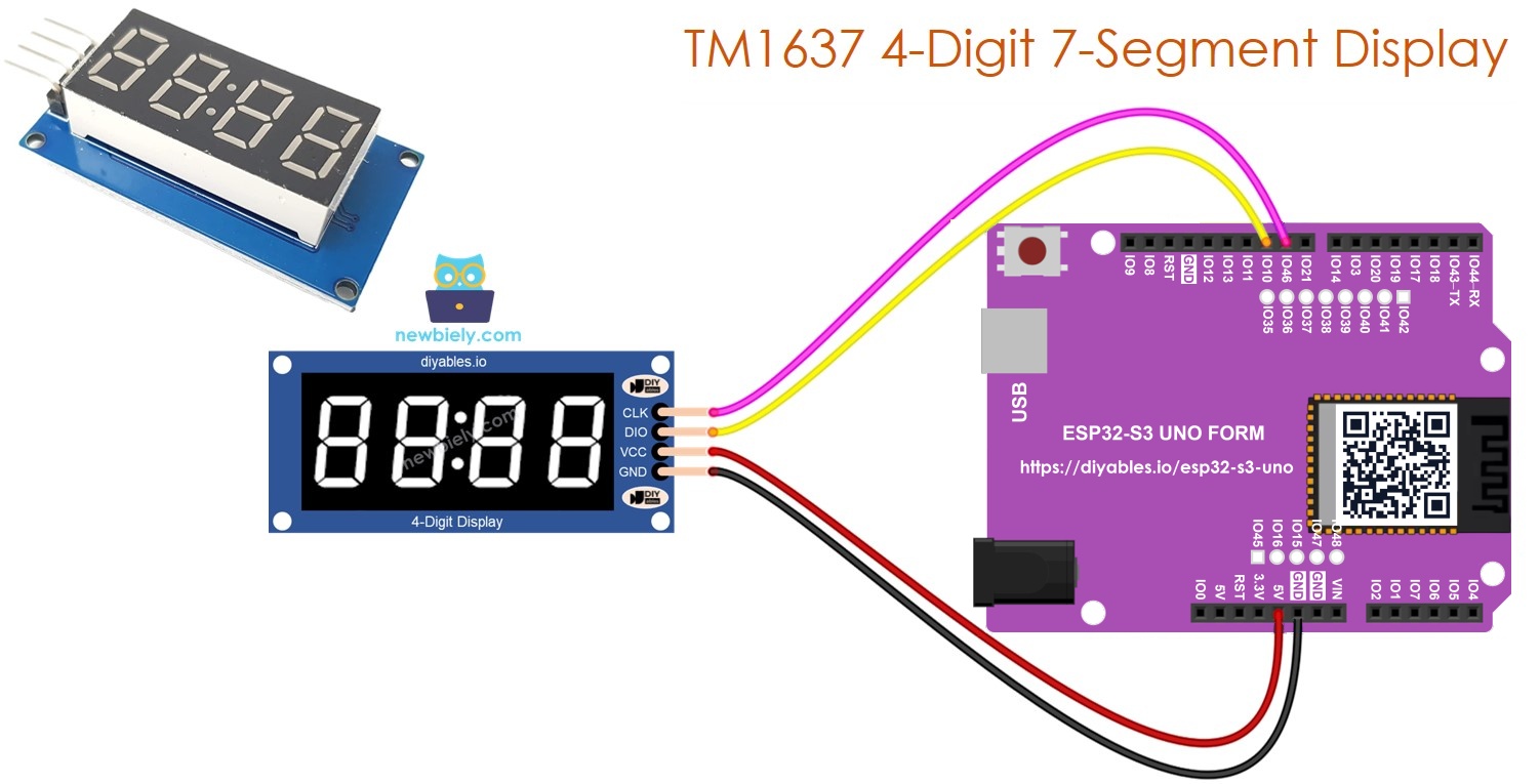
Hardware Preparation
| 1 | × | ESP32 S3 Uno-form Board | |
| 1 | × | USB Cable Type-A to Type-C (for USB-A PC) | |
| 1 | × | USB Cable Type-C to Type-C (for USB-C PC) | |
| 1 | × | TM1637 4-digit 7-segment Display (colon-separated) | |
| 1 | × | Jumper Wires |
Or you can buy the following kits:
| 1 | × | DIYables Sensor Kit (18 sensors/displays) |
Additionally, some of these links are for products from our own brand, DIYables .
TM1637 4-Digit 7-Segment Display Overview
Before you wire anything, it helps to know why this module is so easy to use. The TM1637 chip does all the hard work, so your ESP32 S3 Uno only sends it short data packets.
What the module does
The TM1637 drives four 7-segment LED digits through just two signal lines, CLK and DIO. It handles the LED multiplexing by itself and keeps the shown data in its own memory. Because of this, the digits stay lit even when your code is busy doing something else.
Main features
Each of the four digits has seven segments and a decimal point. A colon LED sits between the second and third digits, which is perfect for clocks. You can pick one of 8 brightness levels, and the module accepts both 3.3V and 5V logic.
Pinout
| Pin | Function |
|---|---|
| CLK | Clock signal input |
| DIO | Data input and output |
| VCC | Power supply (3.3V or 5V) |
| GND | Ground |
You can use any two free digital pins of the ESP32 S3 Uno for CLK and DIO. This tutorial uses D9 and D10.
ESP32 S3 Uno Pinout
The image below shows the pinout of the ESP32 S3 Uno form board. Use it to find the Uno header pins (D9, D10, 3.3V…) and their GPIO numbers while you wire the display.

Wiring Diagram
Only four wires are needed. Follow the image and the table below.
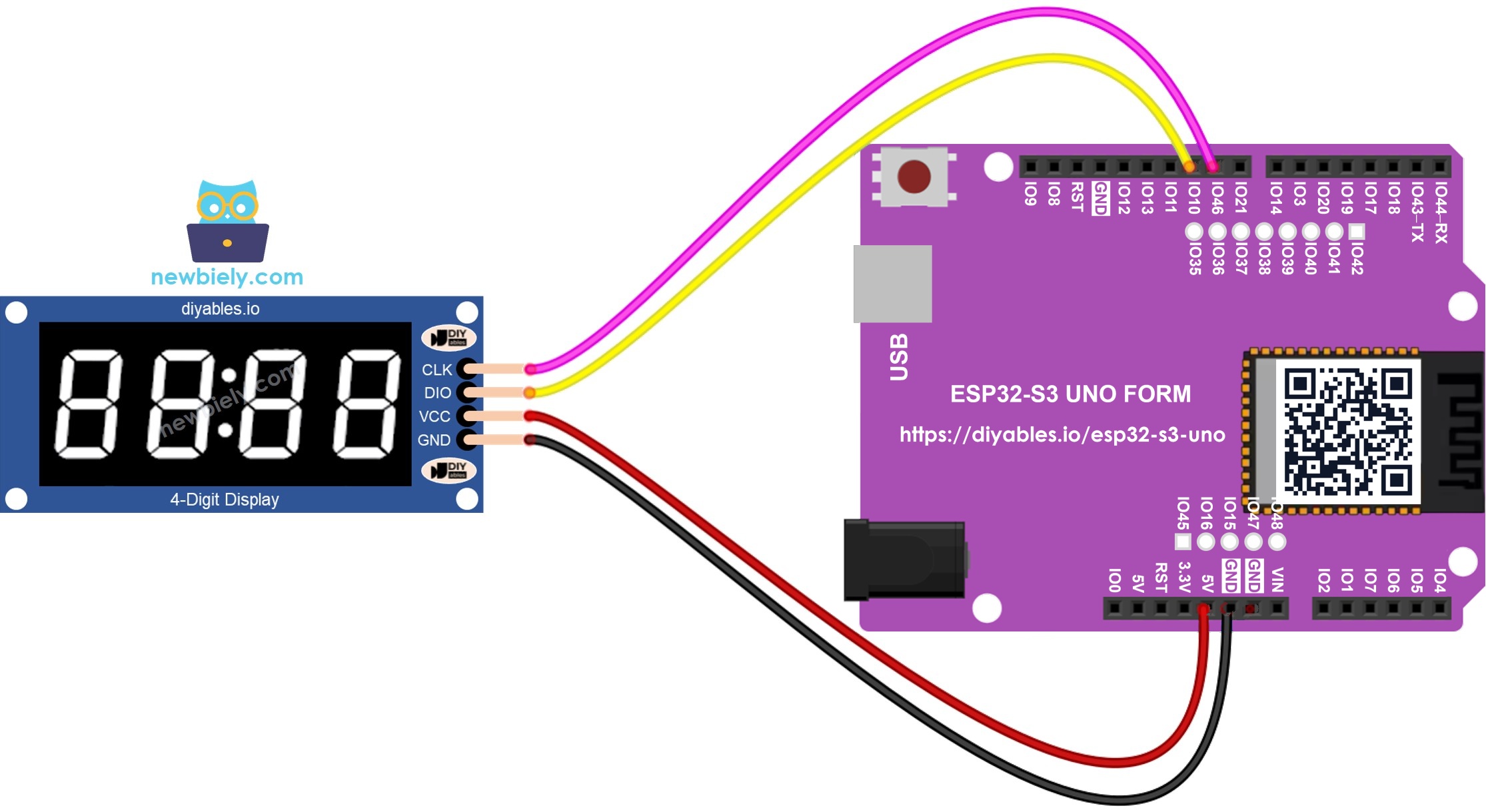
This image is created using Fritzing. Click to enlarge image
| TM1637 Pin | ESP32 S3 Uno Pin |
|---|---|
| CLK | D9 (GPIO46) |
| DIO | D10 (GPIO10) |
| VCC | 3.3V |
| GND | GND |
WARNING
D9 is GPIO46 on the ESP32 S3 Uno, which is a boot strapping pin. The TM1637 module has a pull-up resistor on CLK, and in rare cases this can stop the board from entering upload mode. If an upload fails, unplug the CLK wire, upload the code, then plug the wire back in.
WARNING
ESP32 S3 Uno pins are not 5V tolerant. The TM1637 module pulls CLK and DIO up to its own VCC, so power it from 3.3V, not 5V. The display works fine at 3.3V and the signal lines stay at a safe level.
How to Install the Library
The DIYables_4Digit7Segment_TM1637 library takes care of the TM1637 protocol for you. Install it once and every example below will compile.
- Connect the ESP32 S3 Uno to your computer with a USB Type-C cable.
- Open Arduino IDE, select the ESP32S3 Dev Module board and the correct COM port.
- Click the Libraries icon on the left side bar.
- Type "DIYables_4Digit7Segment_TM1637" in the search box and find the library by DIYables.
- Click Install.
- Search for DIYables_4Digit7Segment_TM1637 created by DIYables.io and click the Install button.
The library has no other dependencies, so nothing else needs to be installed.
Minimal Sketch Structure
Every sketch in this tutorial starts from the same small skeleton. Once you know it, the other examples are easy to read.
You create the display object with the two GPIO numbers, call begin() one time in setup(), and then send data to the display. Note that the code uses GPIO numbers (46 and 10), not the D9 and D10 header labels.
Showing Integer Values
Numbers are the most common thing to show on a 7-segment display. This sketch shows several integers, including negative ones and a zero-padded value.
How to Run
- New to the ESP32 S3 Uno? Follow ESP32 S3 Uno - Getting Started first.
- Wire it up as shown in the wiring diagram.
- Connect the board to your computer with a USB Type-C cable.
- Open Arduino IDE, choose the ESP32S3 Dev Module board and the correct COM port.
- Copy the code above and paste it into Arduino IDE.
- Upload the code by clicking the Upload button.
- Open the Serial Monitor at 9600 baud.
- Tip: If the display stays dark, check the CLK and DIO wires first.
The display shows 0, 42, 1234, -5, -123 and 9999, two seconds each, then "0042" with leading zeros.
Method Quick Reference
| Method | What It Does | Usage |
|---|---|---|
| print(int) | Shows an integer (-999 to 9999) | display.print(1234) |
| print(int, true) | Shows the number with leading zeros | display.print(42, true) |
| clear() | Turns off all segments | display.clear() |
Showing Text and Temperature
A 7-segment display can also show short words and a degree sign. This is handy for status messages and for a simple thermometer.
How to Run
- Keep the same wiring as above.
- Upload the sketch to the ESP32 S3 Uno.
- Open the Serial Monitor to follow what is shown.
- Tip: Some letters, like M and W, cannot be drawn well with seven segments, so pick short words.
The display shows "HELP", "Hi", "COOL" and "done", then "25°C" and "72°F". The last step builds "25°C" by hand with the DEGREE constant.
Method Quick Reference
| Method | What It Does | Usage |
|---|---|---|
| print(const char*) | Shows a string of up to 4 characters | display.print("HELP") |
| printTemperature(int, char) | Shows a temperature with degree sign and unit | display.printTemperature(25, 'C') |
| DEGREE | Degree character for building your own strings | display.DEGREE |
Showing Time with Blinking Colon
The colon in the middle makes this module a natural choice for a clock. This sketch shows a fixed time and turns the colon on and off every half second.
How to Run
- Upload the code with the same wiring.
- Watch the display: it shows "12:30" and the colon blinks twice per second.
- Tip: To build a real clock, get the time from NTP over WiFi or from an RTC module and pass it to printTime().
Method Quick Reference
| Method | What It Does | Usage | |
|---|---|---|---|
| printTime(int, int) | Shows HH | MM with the colon on | display.printTime(12, 30) |
| printTime(int, int, bool) | Shows HH | MM and sets the colon on or off | display.printTime(12, 30, false) |
Blinking the Display On and Off
Blinking is a simple way to grab attention, for example when a timer ends. The off() and on() functions hide and show the content without erasing it.
How to Run
- Upload the code to the ESP32 S3 Uno.
- Watch the display: "1234" blinks five times, then "HELP" blinks five times, and the cycle repeats.
- Tip: Change the delay(300) values to make the blink faster or slower.
Method Quick Reference
| Method | What It Does | Usage |
|---|---|---|
| off() | Turns the display off and keeps the data | display.off() |
| on() | Turns the display back on | display.on() |
| setBrightness(int) | Sets the brightness (0 to 7) | display.setBrightness(4) |
Controlling Individual Digits
Sometimes you want full control over each position, for example to show a score and a label side by side. This sketch sets each digit one by one with numbers, letters and the colon.
How to Run
- Upload the code to the ESP32 S3 Uno.
- Watch the display: it shows 1234, 12:34, HELP, A3:b7 and then 12:30 with a blinking colon.
- Tip: Positions are numbered 0 to 3 from left to right.
Method Quick Reference
| Method | What It Does | Usage |
|---|---|---|
| setNumber(int, int) | Puts a digit 0-9 at a position | display.setNumber(0, 1) |
| setChar(int, char) | Puts a character at a position | display.setChar(0, 'H') |
| setColon(bool) | Turns the colon on or off | display.setColon(true) |
| setSegments(int, uint8_t) | Writes raw segment data | display.setSegments(0, 0x76) |
Platform Support
The library only uses standard Arduino functions: pinMode, digitalWrite, digitalRead and delayMicroseconds. That is why the same code runs on the ESP32 S3 Uno and on other Arduino-compatible boards. You only need to change the two pin numbers.
FAQ
Can I power the TM1637 display from 5V on the ESP32 S3 Uno?
It is better to use 3.3V. The module has pull-up resistors on CLK and DIO that connect to its VCC, so at 5V these lines would carry 5V into the ESP32 S3 Uno pins, which are not 5V tolerant. The display is bright enough at 3.3V.
Why does the code use 46 and 10 instead of D9 and D10?
On the ESP32 S3 Uno, the Uno header labels are only printed names. In code you must write the real GPIO numbers. D9 is GPIO46 and D10 is GPIO10, so the sketch uses 46 and 10.
Can I use other pins for CLK and DIO?
Yes. Any free digital pin works, because the library uses normal digitalWrite and digitalRead calls. Good choices are D2 (GPIO18), D4 (GPIO19), D5 (GPIO20) or D7 (GPIO14). Just change CLK_PIN and DIO_PIN in the code to match.
What if my project needs more pins than the Uno headers give?
The ESP32 S3 Uno has two extra rows of holes with more GPIOs: GPIO15 and GPIO16 (I/O, PWM, analog), GPIO45 and GPIO35 to GPIO42 (I/O, PWM), and GPIO47/GPIO48 (output only, PWM). Solder pin headers to use them and write the GPIO number in code. CLK and DIO of a second TM1637 fit well on GPIO35 to GPIO42; do not use GPIO47/48 for DIO, because DIO must also be read as an input. Be careful with two things. First, GPIO47 and GPIO48 may run at 1.8V instead of 3.3V on some modules (especially ones with "V" in the name, like R8V or R16V), so 3.3V devices can be damaged or act strangely. Second, GPIO0, GPIO3 (D6), GPIO45 and GPIO46 (D9) are boot strapping pins, and a wrong connection can stop the board from booting or uploading code. Use the other extra pins first.
Can I connect two TM1637 displays to one ESP32 S3 Uno?
Yes. Each display needs its own pair of CLK and DIO pins. Create two display objects, for example display1(46, 10) and display2(14, 18), and call begin() on both.
How do I make a real clock with this display?
The time example only shows a fixed value. For a real clock, read the time from the internet with NTP over the ESP32 S3 Uno WiFi, or from an RTC module such as the DS3231, and pass the hours and minutes to printTime().
Troubleshooting
| Problem | Possible Cause | Solution |
|---|---|---|
| No COM port appears in Arduino IDE | USB driver missing or charge-only cable | Install the CP210x or CH340 driver, try a data USB Type-C cable, or hold BOOT while pressing RESET |
| Upload fails while the display is wired | Pull-up on CLK affects the GPIO46 boot strapping pin | Unplug the CLK wire, upload the code, then plug it back in |
| Nothing appears on the display | Loose wire, no power, or wrong pin numbers in code | Check VCC to 3.3V and GND, and make sure CLK_PIN is 46 and DIO_PIN is 10 |
| Wrong or random characters | CLK and DIO wires are swapped | Swap the two signal wires or swap the pin numbers in code |
| Display is too dim | Brightness level is low | Call display.setBrightness(7) for full brightness |
| Compile error about DIYables_4Digit7Segment_TM1637.h | Library is not installed | Install DIYables_4Digit7Segment_TM1637 from the Library Manager |
| Serial Monitor shows strange symbols | Baud rate does not match the code | Set the Serial Monitor to 9600 baud |