
ESP32 S3 UNO - IR Slotted Optical Speed Sensor
This ESP32 S3 Uno IR slotted optical speed sensor tutorial shows you how to wire the U-shaped sensor to the ESP32 S3 Uno form board and read it with Arduino code. The module is also called a photo interrupter or opto interrupter. You will count objects that pass through the slot, and then turn it into a simple tachometer that shows motor speed in RPM.
In this tutorial, you will:
- Learn how a photo interrupter detects an object between its two arms
- Wire the IR slotted optical speed sensor to the ESP32 S3 Uno
- Count objects in the slot with digitalRead()
- Measure motor speed (RPM) with an encoder disc and an interrupt
Hardware Preparation
| 1 | × | ESP32 S3 Uno-form Board | |
| 1 | × | USB Cable Type-A to Type-C (for USB-A PC) | |
| 1 | × | USB Cable Type-C to Type-C (for USB-C PC) | |
| 1 | × | IR Slotted Optical Speed Sensor | |
| 1 | × | Jumper Wires | |
| 1 | × | Optionally, Breadboard |
Or you can buy the following kits:
| 1 | × | DIYables Sensor Kit (18 sensors/displays) |
Additionally, some of these links are for products from our own brand, DIYables .
Overview of IR Slotted Optical Speed Sensor
Before you wire anything, it helps to know what is inside this little U-shaped block. Once you see how simple it is, the code will make sense right away.
The module has two arms with a 5.9 mm gap between them. One arm holds an infrared LED, and the other holds an NPN phototransistor. They look at each other across the gap. So the sensor answers just one question for the ESP32 S3 Uno: is the gap empty, or is something in it?
| IR Slotted Optical Speed Sensor | |
|---|---|
| Sensor type | slot-type photoelectric (IR LED + NPN phototransistor) |
| Slot width | 5.9 mm |
| Operating voltage | 3.3V to 5V DC |
| Output | digital (TTL), LOW when blocked, HIGH when clear |
| Signal conditioning | built-in Schmitt trigger |
| Mounting | M3 screw holes at both ends |
| Pins | 3 (VCC, GND, OUT) |
You will find this sensor in many projects. It works as a tachometer when you add an encoder disc to a motor. It can count objects or pulses, and it can measure distance by counting wheel turns. Robots use it for wheel speed feedback, and machines use it to find a limit or home position.
Pinout
The module has only three pins, so wiring is quick.
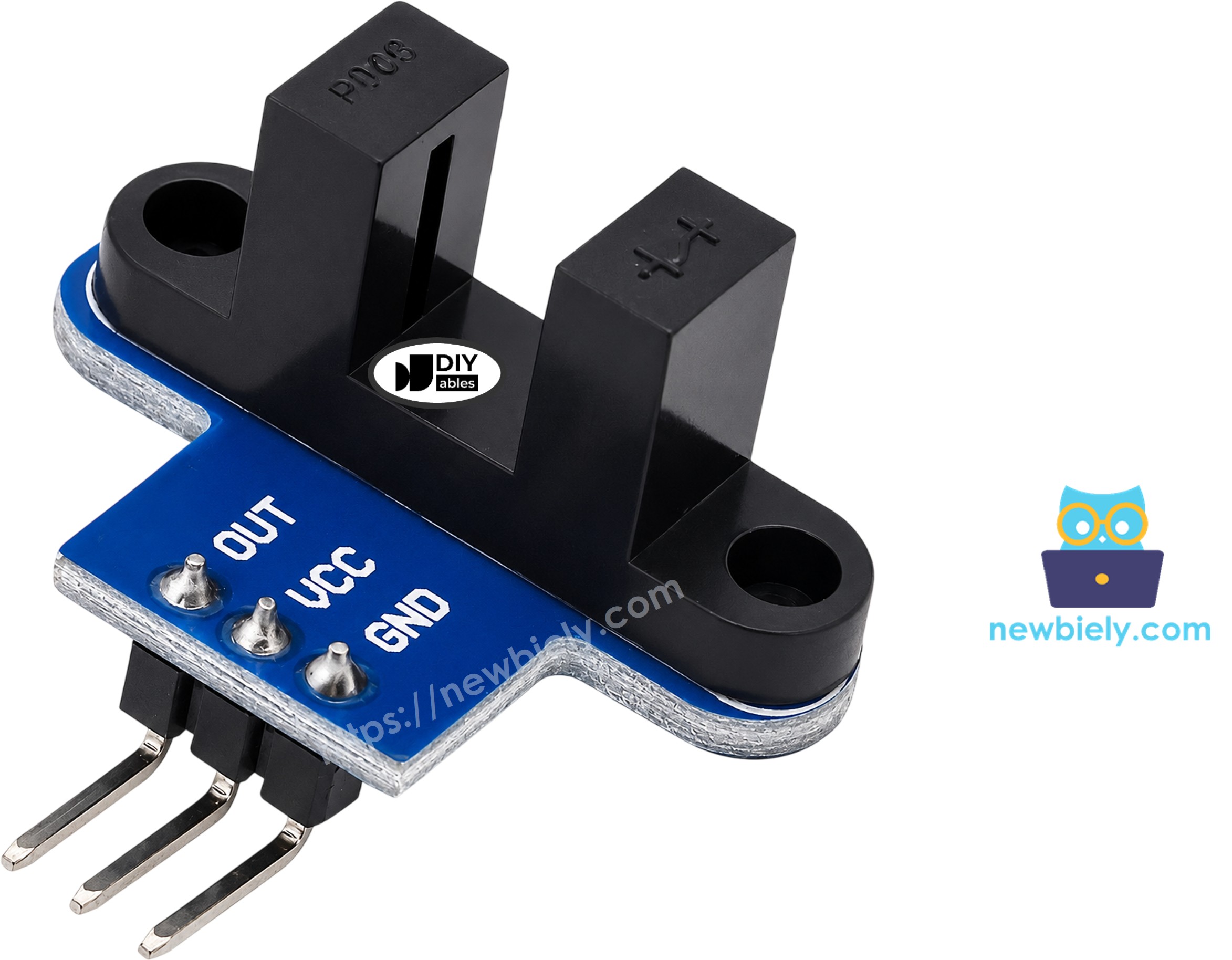
VCC pin
Connect it to the 3.3V pin of the ESP32 S3 Uno. The module works from 3.3V to 5V, but 3.3V keeps the output safe for the board.
GND pin
Connect it to GND (0V).
OUT pin
This is the digital output. Connect it to an input pin of the ESP32 S3 Uno.
The pin order can be different from one batch to the next. Always check the labels printed on your module before you connect it.
How It Works
The idea is simple: light either reaches the receiver, or it does not.

The IR LED shines across the slot all the time. When the slot is empty, the light hits the phototransistor and the OUT pin is HIGH. When something opaque is in the slot (a card, a finger or a tooth of an encoder disc), the light is blocked and the OUT pin goes LOW.
A Schmitt trigger on the module turns the raw light level into a clean 0 or 1. The signal does not bounce, so you do not need software debounce.
Two things to watch for
Clear plastic or glass can let IR light pass, so the sensor may not see it. Use opaque objects. Also, some modules from other makers work the other way round. If your sensor says "blocked" when the slot is empty, swap LOW and HIGH in the first sketch. The RPM sketch counts one edge per slot, so it works with both types.
How To Program For IR Slotted Optical Speed Sensor
There are two ways to read this sensor. Polling is easy and good for slow objects. An interrupt is the right tool when a disc spins fast.
Check if the slot is blocked (polling)
- Set the pin connected to OUT as an input:
- Read the pin. LOW means blocked, HIGH means clear:
- Compare it with the last reading, so you only react when the state changes:
Count fast pulses (interrupt)
- Create a counter. Make it volatile, because the interrupt changes it:
- Write a short function that adds one to the counter. On the ESP32 S3 Uno, add IRAM_ATTR so the function sits in fast RAM:
- Call that function each time the signal falls from HIGH to LOW (a tooth enters the slot):
- Once per second, copy and reset the counter with interrupts paused, then convert pulses to RPM:
Where does the formula come from? A 20-slot disc makes 20 pulses in one full turn. Multiply the pulses in 1 second by 60 to get pulses per minute. Then divide by 20 to get turns per minute, which is RPM.
ESP32 S3 Uno Pinout
The image below shows the pinout of the ESP32 S3 Uno form board. Use it to find the D2 header pin and its GPIO number before you wire the sensor.

Wiring Diagram
You need just three wires. Power the sensor from 3.3V, connect GND to GND, and connect OUT to D2.
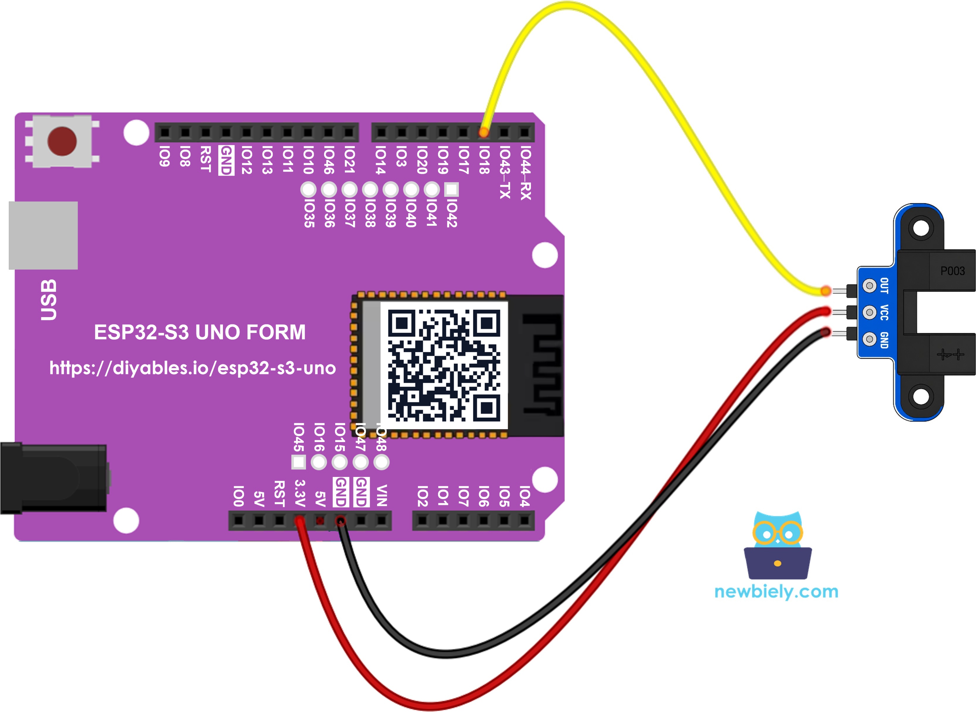
This image is created using Fritzing. Click to enlarge image
| Speed Sensor Pin | ESP32 S3 Uno Pin |
|---|---|
| VCC | 3.3V |
| GND | GND |
| OUT | D2 (GPIO18) |
Any ESP32 S3 Uno GPIO can run an interrupt, and D2 is a safe, normal pin. The RPM sketch below uses that interrupt.
WARNING
ESP32 S3 Uno pins are NOT 5V tolerant. If you power the sensor from 5V, its OUT pin also gives 5V, which can damage GPIO18. Power the module from 3.3V (it works fine there), or add a voltage divider or level shifter on the OUT line if you must use 5V.
ESP32 S3 Uno Code - Detect Object in the Slot
This sketch reads the OUT pin over and over. It prints a line only when the state changes, and it adds one to a counter every time the slot gets blocked.
Detailed Instructions
- New to the ESP32 S3 Uno? Follow ESP32 S3 Uno - Getting Started first.
- Wire it up as shown in the diagram.
- Connect the board to your computer with a USB Type-C cable.
- Open Arduino IDE, choose the ESP32S3 Dev Module board and the correct COM port.
- Copy the code above and paste it into the Arduino IDE.
- Upload the sketch with the Upload button.
- Open the Serial Monitor and set it to 9600 baud.
- Test it by sliding a piece of card (or your finger) into the slot and pulling it out a few times.
- Check the output on the Serial Monitor:
- Tip: If nothing prints, look at the small LED on the module (if it has one). It should change when you block the slot. If it does, check the OUT wire to D2.
Every pass gives two lines: one when the card goes in, and one when it comes out. While nothing moves, nothing is printed.
ESP32 S3 Uno Code - Measure Motor Speed (RPM)
Polling inside loop() works for slow objects, but a spinning disc is much faster and loop() could miss teeth. This sketch counts pulses with an interrupt on the FALLING edge, so each tooth gives exactly one count. Every second it prints the pulse count and the speed in RPM.
SLOTS_PER_TURN is set to 20, which matches the common encoder disc sold with TT gear motors. If your disc has a different number of slots, change this value.
The only ESP32 S3 Uno change in this sketch is IRAM_ATTR on the interrupt function. It places the function in internal RAM, so it runs quickly and safely even while the chip reads its flash memory.
Set Up the Encoder Disc
The disc turns rotation into pulses, so it must sit in the right place.
- Fix the encoder disc on the motor shaft or the wheel.
- Place the sensor so the teeth of the disc pass through the slot.
- Make sure the disc does not rub against the sensor arms.
- Spin the disc by hand, or power the motor. The motor needs its own wiring; see the ESP32 S3 Uno - DC Motor tutorial for that part.
Detailed Instructions
- Keep the wiring the same as before.
- Copy the RPM code above and paste it into the Arduino IDE.
- Upload the sketch with the Upload button.
- Open the Serial Monitor at 9600 baud.
- Spin the disc, then let it stop.
- Read the speed on the Serial Monitor. In this example the motor runs at about 300 RPM:
- Tip: Check one line by hand. 100 pulses × 60 ÷ 20 = 300 RPM.
Do you want to know how far a wheel has moved? Multiply the number of turns by the wheel circumference (π × wheel diameter).
※ NOTE THAT:
- Keep the interrupt function short, and never call Serial.print() inside it.
- Every variable the interrupt changes must be volatile.
- To sense an object at a distance instead of inside a slot, try the obstacle avoidance sensor. For a knob that also gives turn direction, try the rotary encoder.
Video Tutorial
Watch the video below to see this ESP32 S3 Uno project step by step.
Function References
FAQ
Can I power the IR slotted optical speed sensor from 5V on the ESP32 S3 Uno?
The module itself runs on 5V, but then its OUT pin also outputs 5V. ESP32 S3 Uno pins are 3.3V only and are not 5V tolerant. Power the sensor from 3.3V, or put a voltage divider on the OUT line if you need 5V.
Which ESP32 S3 Uno pin should I use for the OUT signal?
This tutorial uses D2 (GPIO18). On the ESP32 S3 Uno every GPIO can trigger an interrupt, so D3, D4, D5 or D7 also work. Avoid D6 (GPIO3) and D9 (GPIO46), because they are boot strapping pins.
Why does the ESP32 S3 Uno interrupt function use IRAM_ATTR?
IRAM_ATTR stores the function in internal RAM. Without it, an interrupt that fires while the chip reads flash can crash the board. The UNO R4 does not need this keyword, but on the ESP32 S3 Uno it is good practice for every interrupt function.
How fast a motor can the ESP32 S3 Uno measure?
The interrupt can count many thousands of pulses per second, so the board is rarely the limit. The sensor response time and the number of disc slots set the real limit. For very fast motors, use a disc with fewer slots.
My RPM value jumps around. How can I make it smoother?
A 1-second window with a 20-slot disc gives a resolution of 3 RPM. Use a longer time window, or average the last few readings. Also make sure the disc is centered and does not wobble in the slot.
What if my project needs more pins than the Uno headers give?
The ESP32 S3 Uno has two extra rows of holes with more GPIOs: GPIO15 and GPIO16 (I/O, PWM, analog), GPIO45 and GPIO35 to GPIO42 (I/O, PWM), and GPIO47/GPIO48 (output only, PWM). Solder pin headers to use them and write the GPIO number in code. A second speed sensor fits well on GPIO35 to GPIO42 or GPIO15/16; do not use GPIO47/48, because they are output only. Be careful: GPIO47 and GPIO48 may run at 1.8V instead of 3.3V on some modules (especially ones with "V" in the name, like R8V or R16V), so 3.3V devices can be damaged or act strangely. Also, GPIO0, GPIO3 (D6), GPIO45 and GPIO46 (D9) are boot strapping pins, and a wrong connection can stop the board from booting or uploading code. Use the other extra pins first.
Troubleshooting
| Problem | Possible Cause | Solution |
|---|---|---|
| No COM port in Arduino IDE | USB driver missing or board not in upload mode | Install the CP210x or CH340 driver, use a data USB cable, or hold BOOT while you press RESET |
| Nothing prints on the Serial Monitor | Wrong baud rate or wrong board selected | Set the Serial Monitor to 9600 baud and choose ESP32S3 Dev Module |
| State never changes | Loose wire or wrong pin order on the module | Check VCC, GND and OUT against the labels on your module and use D2 (GPIO18) |
| Blocked and clear are swapped | The module has inverted output | Swap LOW and HIGH in the first sketch |
| Object is not detected | Object is transparent or too thin | Use an opaque card or object that fully covers the slot |
| RPM reads 0 while the disc spins | Disc teeth do not pass the slot or wiring is wrong | Move the sensor so the teeth cross the gap and check the OUT wire |
| RPM value is too high or too low | SLOTS_PER_TURN does not match the disc | Count the slots on your disc and update SLOTS_PER_TURN |
| Board resets or GPIO stops working | Sensor powered from 5V sends 5V into the pin | Power the sensor from 3.3V or add a voltage divider on OUT |