
ESP32 S3 UNO - Automated Light Control with Motion Sensor and LED Strip
This ESP32 S3 Uno motion sensor LED strip project shows you how to make a light that turns on by itself when someone walks by. You connect an HC-SR501 PIR sensor and a relay to the ESP32 S3 Uno form board, and the relay switches a 12V LED strip. It is a simple and energy-saving piece of smart home automation.
In this tutorial, you will:
- Wire an HC-SR501 motion sensor and a relay to the ESP32 S3 Uno
- Switch a 12V LED strip safely through a relay
- Set up the motion sensor adjusters for fast testing
- Upload automated light control code from Arduino IDE
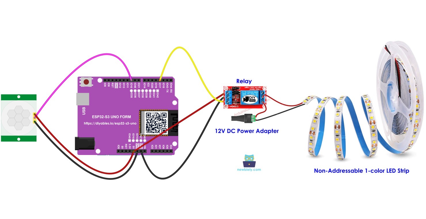
You can use the same idea in many places around your home:
Automatic stair lighting
The stairs light up when someone comes close, so nobody walks in the dark.
Under-bed lighting
A soft light glows when you put your feet on the floor at night.
Christmas tree lights
The tree lights turn on when people are nearby, and turn off when the room is empty.
Hardware Preparation
Or you can buy the following kits:
| 1 | × | DIYables Sensor Kit (18 sensors/displays) |
Additionally, some of these links are for products from our own brand, DIYables .
Overview of LED Strip and Motion Sensor
This project puts two parts together. If one of them is new to you, read its own tutorial first. There you will learn the pinout, how it works, and how to code it on the ESP32 S3 Uno.
In short, the HC-SR501 sees the body heat of a person and sets its OUTPUT pin HIGH. The LED strip needs 12V, which the board cannot give, so a relay works as a switch between the 12V power adapter and the strip. The ESP32 S3 Uno reads the sensor and turns the relay on or off.
ESP32 S3 Uno Pinout
The image below shows the pinout diagram of the ESP32 S3 Uno form board. Use it to find the D3 and D10 headers and their GPIO numbers when you wire the circuit.

Wiring Diagram
Connect the motion sensor and the relay to the board as shown below. The 12V side (power adapter, relay contacts and LED strip) is fully separate from the board pins.
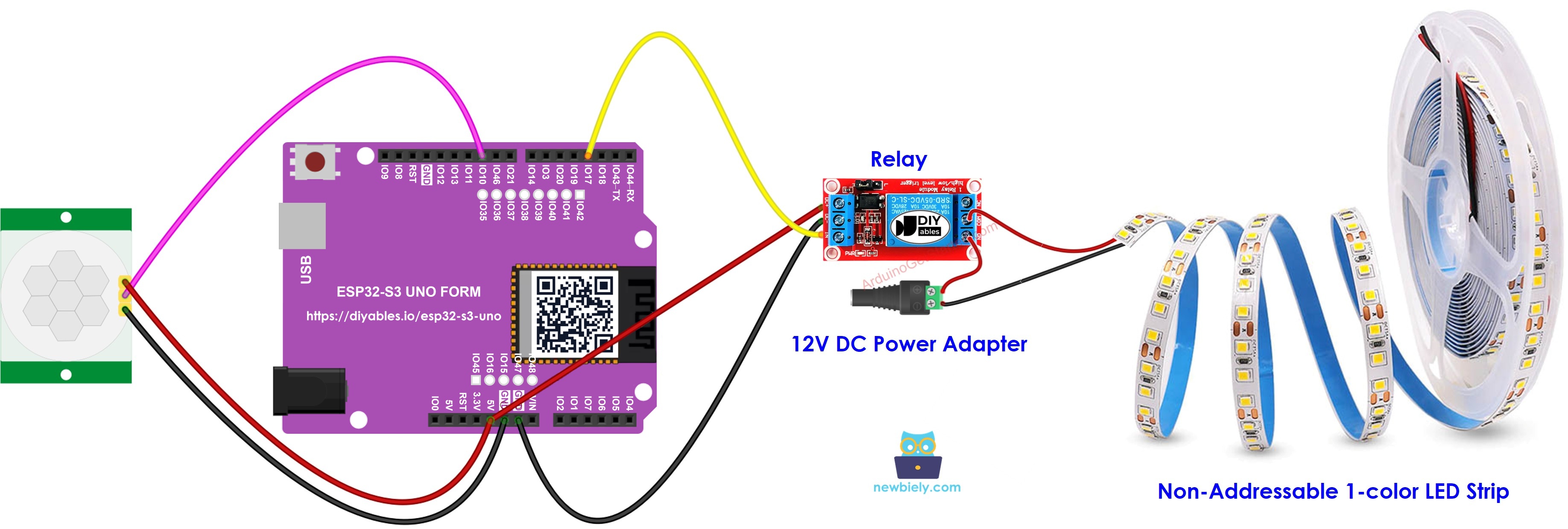
This image is created using Fritzing. Click to enlarge image
| Component Pin | ESP32 S3 Uno Pin |
|---|---|
| Motion sensor VCC | 5V |
| Motion sensor GND | GND |
| Motion sensor OUTPUT | D10 (GPIO10) |
| Relay VCC | 5V |
| Relay GND | GND |
| Relay IN | D3 (GPIO17) |
On the 12V side, the relay's COM and NO screw terminals sit in the positive wire between the 12V power adapter (through the DC power jack) and the LED strip. The negative wire of the adapter goes straight to the negative pad of the strip.
※ NOTE THAT:
The HC-SR501 can be powered from 5V, but its OUTPUT pin gives about 3.3V. This is safe for the ESP32 S3 Uno, whose pins are NOT 5V tolerant. Do not connect any other 5V signal to D10 (GPIO10).
WARNING
Never connect the 12V supply to any ESP32 S3 Uno pin. Keep the 12V wires on the relay contacts only.
Initial Setting
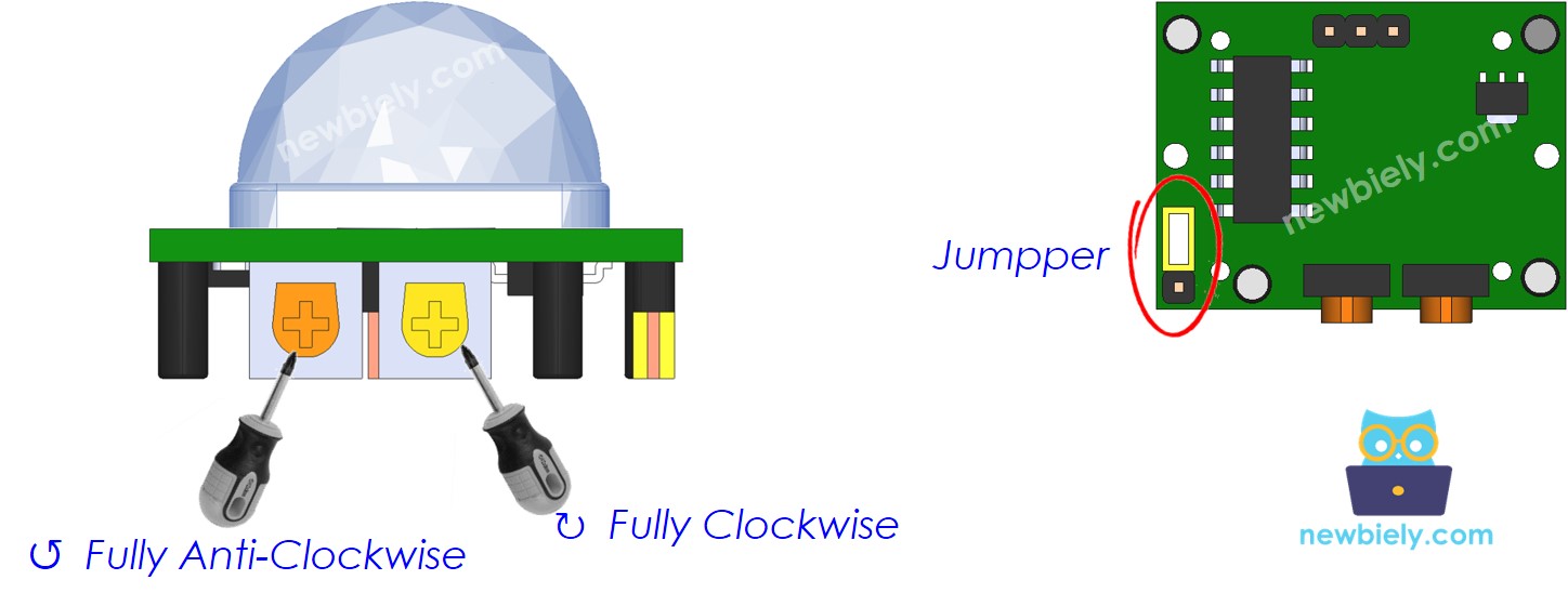
The HC-SR501 has two small screws and a jumper on its back. Set them like this before you start, so the light reacts quickly and you can test it without waiting.
| Time Delay Adjuster | Screw it in anti-clockwise direction fully. |
| Detection Range Adjuster | Screw it in clockwise direction fully. |
| Repeat Trigger Selector | Put jumper as shown on the image. |
ESP32 S3 Uno Code - Motion Sensor Controls LED strip
The sketch reads the motion sensor on D10 (GPIO10) in every loop and keeps the last state. When the state changes from LOW to HIGH, it turns the relay on D3 (GPIO17) on, so the LED strip lights up. When it changes from HIGH to LOW, it turns the relay off and the strip goes dark.
Detailed Instructions
Follow these steps in order:
- New to the ESP32 S3 Uno? Follow ESP32 S3 Uno - Getting Started first.
- Wire it up as shown in the diagram.
- Connect the board to your computer with a USB Type-C cable.
- Open Arduino IDE, choose the ESP32S3 Dev Module board and the correct COM port.
- Copy the code above and paste it into Arduino IDE.
- Upload the code by clicking the Upload button.
- Plug in the 12V power adapter for the LED strip.
- Wave your hand in front of the motion sensor.
- Look at the LED strip. It turns on when motion is seen and turns off when the motion stops.
- Open the Serial Monitor at 9600 baud to see the messages.
- Tip: After you finish testing, turn the Time Delay Adjuster clockwise to keep the light on longer, for example on a staircase.
Video Tutorial
Watch the video below to see this ESP32 S3 Uno project step by step.
Summary
You built an automatic light with the ESP32 S3 Uno, an HC-SR501 motion sensor, a relay and a 12V LED strip. The board watches the sensor and turns the strip on only when someone is near, so you save energy.
You can use the same circuit for stair lights, under-bed lights or Christmas tree lights. Try changing the sensor settings or the code to fit your own lighting ideas.
FAQ
Can the ESP32 S3 Uno power a 12V LED strip directly?
No. The board pins give only 3.3V and a very small current. Use a relay (or a MOSFET) and a separate 12V power adapter for the strip. The board only drives the relay's IN pin.
Is the HC-SR501 safe to use with the 3.3V pins of the ESP32 S3 Uno?
Yes. You power the sensor from 5V, but its OUTPUT pin gives about 3.3V when it detects motion. That level is safe for the ESP32 S3 Uno, whose pins are not 5V tolerant.
Will a 5V relay module work with the ESP32 S3 Uno?
Most 5V relay modules switch fine with a 3.3V signal on the IN pin. Power the module from the 5V pin. If your relay does not click, use a relay module rated for 3.3V input, or add a small transistor driver.
How do I keep the LED strip on for longer after motion stops?
Turn the Time Delay Adjuster on the HC-SR501 clockwise. It sets how long the OUTPUT stays HIGH, from a few seconds up to a few minutes. The code follows the sensor, so the strip stays on for the same time.
What if my project needs more pins than the Uno headers give?
The ESP32 S3 Uno has two extra rows of holes with more GPIOs. GPIO15 and GPIO16 support I/O, PWM and analog. GPIO45 and GPIO35 to GPIO42 support I/O and PWM. GPIO47 and GPIO48 are output only, with PWM. Solder pin headers to use them and write the GPIO number in your code. For more motion sensors use inputs like GPIO35 to GPIO42, not GPIO47/48. For more relays any of GPIO35 to GPIO42 work well. Be careful with two things. First, GPIO47 and GPIO48 may run at 1.8V instead of 3.3V on some modules (especially ones with "V" in the name, like R8V or R16V), so 3.3V devices can be damaged or act strangely. Second, GPIO0, GPIO3 (D6), GPIO45 and GPIO46 (D9) are boot strapping pins, and a wrong connection can stop the board from booting or uploading code. Use the other extra pins first.
Is this code different from the UNO R4 version?
Only the pin numbers change. On the ESP32 S3 Uno you write the GPIO number in code, so D10 becomes 10 and D3 becomes 17. The logic is the same.
Troubleshooting
| Problem | Possible Cause | Solution |
|---|---|---|
| No COM port in Arduino IDE | USB driver missing or charge-only cable | Install the CP210x or CH340 driver, use a data USB cable, or hold BOOT while you press RESET |
| LED strip never turns on | Wrong wiring on the 12V side | Check that COM and NO are in the positive wire and the adapter is plugged in |
| Relay clicks but the strip stays off | Strip connected to NC instead of NO | Move the wire from the NC terminal to the NO terminal |
| Relay never clicks | Relay IN not on D3 or relay not powered | Connect IN to D3 (GPIO17) and VCC to 5V, and check the GND wire |
| Serial Monitor shows nothing | Wrong baud rate | Set the Serial Monitor to 9600 baud |
| Light turns on by itself | Sensor sees heat or moving air | Point the sensor away from heaters, windows and fans, and lower the detection range |
| Light stays on too long | Time Delay Adjuster set high | Turn the Time Delay Adjuster anti-clockwise |
| Sensor does not react right after power on | HC-SR501 needs warm-up time | Wait about 30 to 60 seconds after power on before testing |