
ESP32 S3 UNO - Temperature Sensor
This ESP32 S3 Uno temperature sensor tutorial shows you how to wire a DS18B20 to the ESP32 S3 Uno form board and read the temperature with Arduino code. The DS18B20 is a 1-wire temperature sensor, so it needs only one data pin. You will see the temperature in both Celsius and Fahrenheit on the Serial Monitor.
In this tutorial, you will:
- Wire the DS18B20 1-wire temperature sensor to the ESP32 S3 Uno on a breadboard.
- Connect the DS18B20 sensor the easy way with a wiring adapter.
- Install the DallasTemperature and OneWire libraries in the Arduino IDE.
- Read the temperature in Celsius and convert it to Fahrenheit.
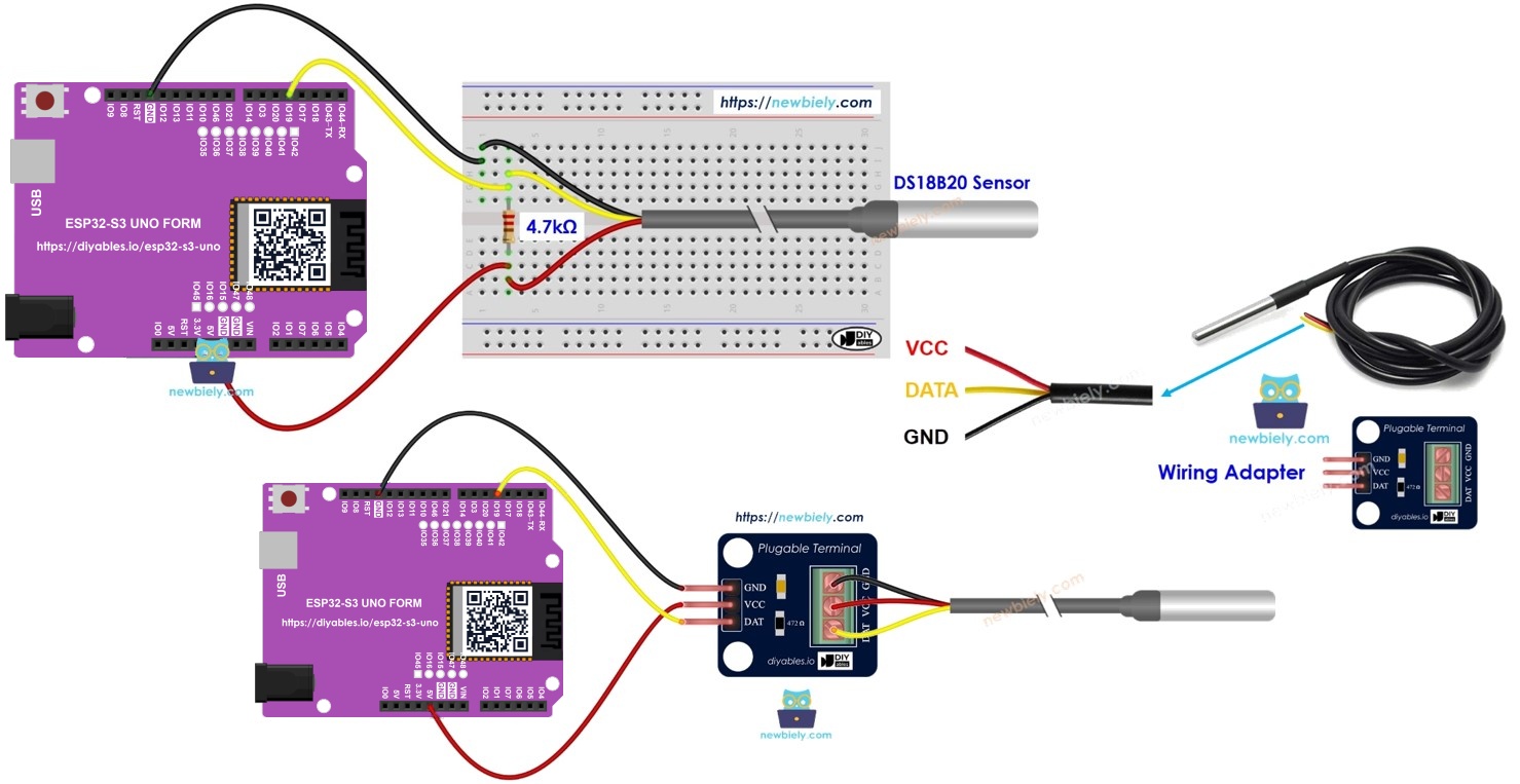
Hardware Preparation
Or you can buy the following kits:
| 1 | × | DIYables Sensor Kit (18 sensors/displays) |
Additionally, some of these links are for products from our own brand, DIYables .
Buy Note: Many DS18B20 sensors available in the market are unreliable. We strongly recommend buying the sensor from the DIYables brand using the link provided above. We tested it, and it worked reliably.
Overview of One Wire Temperature Sensor DS18B20
The DS18B20 is a digital temperature sensor. It sends the temperature as data over a single wire, so the ESP32 S3 Uno does not need an analog pin to read it. Knowing its three pins makes the wiring step quick and safe.
Pinout
The DS18B20 has three pins. Each one has a simple job.
| Pin | What it does |
|---|---|
| GND | Ground. Connect it to GND (0V). |
| VCC | Power. Connect it to 3.3V or 5V. Use 3.3V with the ESP32 S3 Uno. |
| DATA | The 1-Wire data bus. Connect it to a digital pin on the ESP32 S3 Uno. |
You can buy the sensor in two forms. One looks like a small transistor (TO-92 package). The other is a waterproof probe on a cable. This tutorial uses the waterproof probe.
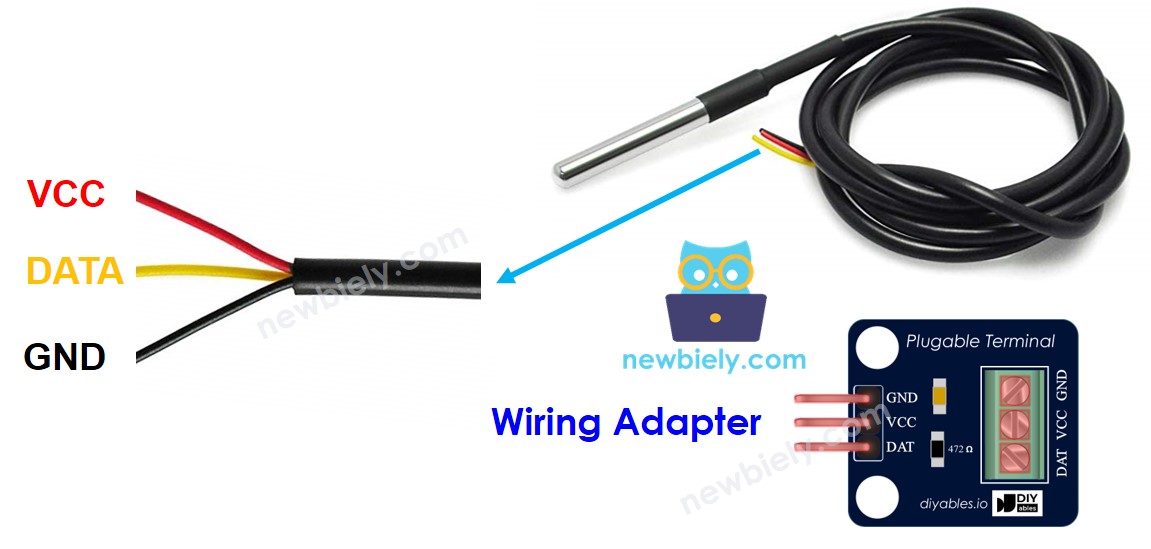
Why a pull-up resistor is needed
The DATA line needs a pull-up resistor (usually 4.7 kΩ) between DATA and VCC. Adding it on a breadboard takes extra parts and care. Some makers sell the sensor with a wiring adapter. The adapter already has the pull-up resistor and a screw terminal block, so the setup is much easier.
ESP32 S3 Uno Pinout
The image below shows the pinout of the ESP32 S3 Uno form board. Use it to find the Uno header pins (D4, 3.3V, GND…) and their GPIO numbers before you wire the sensor.

Wiring Diagram
You can wire the sensor in two ways. Pick the breadboard version if you have a bare sensor and a resistor, or the adapter version for a cleaner setup.
Breadboard wiring
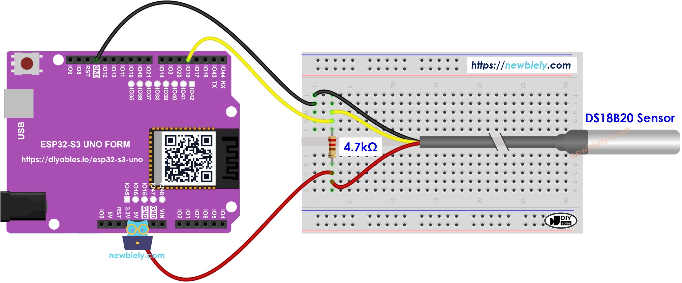
This image is created using Fritzing. Click to enlarge image
Wiring with the adapter
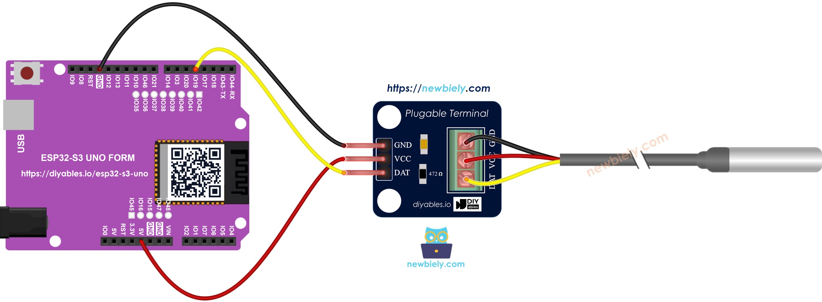
This image is created using Fritzing. Click to enlarge image
| DS18B20 Pin | ESP32 S3 Uno Pin |
|---|---|
| VCC | 3.3V |
| GND | GND |
| DATA | D4 (GPIO19) |
If you use the bare sensor, put a 4.7 kΩ resistor between DATA and 3.3V. The adapter already has this resistor inside.
WARNING
The ESP32 S3 Uno pins work at 3.3V and are NOT 5V tolerant. Power the DS18B20 from 3.3V so the DATA line, pulled up by the resistor, never goes above 3.3V. If you power the sensor from 5V, the pull-up pushes 5V into D4 (GPIO19) and can damage the pin.
We suggest the DS18B20 sensor with a wiring adapter. It has the resistor built in, so you need no extra parts.
How To Program For DS18B20 Temperature Sensor
Reading the DS18B20 takes only a few library calls. The steps below show each part on its own, so the full sketch is easy to follow later.
- Include the two libraries:
- Create a OneWire object on the pin wired to the DATA pin, then pass it to a DallasTemperature object:
- Start the sensor in setup():
- Ask the sensor to measure the temperature:
- Read the result in Celsius:
- (Optional) Convert Celsius to Fahrenheit:
ESP32 S3 Uno Code
The sketch below reads the DS18B20 on D4 (GPIO19) every half second. It prints the temperature in Celsius and Fahrenheit to the Serial Monitor. Note that the code uses the GPIO number 19, not the label D4.
Detailed Instructions
Follow these steps in order:
- New to the ESP32 S3 Uno? Follow ESP32 S3 Uno - Getting Started first.
- Wire it up as shown in the diagram above.
- Connect the board to your computer with a USB Type-C cable.
- Open Arduino IDE, choose the ESP32S3 Dev Module board and the correct COM port.
- Open the library manager by clicking the Libraries icon on the left side of the Arduino IDE.
- Find the library by searching for DallasTemperature by Miles Burton.
- Install it by clicking the Install button.
- Search for DallasTemperature created by Miles Burton
- Install the dependency when the IDE asks. Click Install All to add the OneWire library too.
- Copy the code above and paste it into the Arduino IDE.
- Upload the code by clicking the Upload button.
- Test the sensor by putting it in warm and cold water, or by holding it in your hand.
- Check the result on the Serial Monitor (set it to 9600 baud).
- Tip: If the value changes slowly, that is normal for the waterproof probe. The metal tube needs a few seconds to reach the new temperature.
Video Tutorial
Watch the video below to see this ESP32 S3 Uno project step by step.
FAQ
Can I power the DS18B20 from 3.3V on the ESP32 S3 Uno?
Yes. The DS18B20 works from 3.0V to 5.5V, so 3.3V is fine. It is also the safe choice, because the ESP32 S3 Uno pins are not 5V tolerant. Pull the DATA line up to 3.3V, not 5V.
Which ESP32 S3 Uno pin should I use for the DS18B20 DATA line?
This tutorial uses D4, which is GPIO19, so the code has #define SENSOR_PIN 19. Any normal digital pin works. Avoid D0 and D1 (USB serial) and the boot strapping pins D6 (GPIO3) and D9 (GPIO46). Always write the GPIO number in code, not the D label.
Can I connect several DS18B20 sensors to one pin?
Yes. The 1-Wire bus lets many sensors share the same DATA pin and one pull-up resistor. Each sensor has its own 64-bit address. Read them with getTempCByIndex(0), getTempCByIndex(1) and so on.
Why does the Serial Monitor show -127°C?
The value -127 means the library could not find the sensor. Usually the DATA wire is loose, on the wrong pin, or the pull-up resistor is missing. Check the wiring and the pin number in the code.
Is the code different from the UNO R4 version?
Only the pin number changes. The DallasTemperature and OneWire libraries work on the ESP32 S3 Uno without any change. On the UNO R4 the sketch used pin 4; here it uses GPIO19, which sits at the same D4 header position.
What if my project needs more pins than the Uno headers give?
The ESP32 S3 Uno has two extra rows of holes with more GPIOs. GPIO15 and GPIO16 support I/O, PWM and analog. GPIO45 and GPIO35 to GPIO42 support I/O and PWM. GPIO47 and GPIO48 are output only, with PWM. Solder pin headers to use them and write the GPIO number in code. For extra DS18B20 buses or other sensors, GPIO15, GPIO16 or GPIO35 to GPIO42 are good picks. Do not use GPIO47 or GPIO48, because a sensor DATA line needs input. Two warnings: (1) GPIO47 and GPIO48 may run at 1.8V instead of 3.3V on some modules (especially ones with "V" in the name, like R8V or R16V), so 3.3V devices can be damaged or act strangely. (2) GPIO0, GPIO3 (D6), GPIO45 and GPIO46 (D9) are boot strapping pins. A wrong connection can stop the board from booting or uploading code. Use the other extra pins first.
Troubleshooting
| Problem | Possible Cause | Solution |
|---|---|---|
| No COM port in Arduino IDE | USB driver missing or charge-only cable | Install the CP210x or CH340 driver, use a data USB cable, or hold BOOT while pressing RESET |
| Temperature always reads -127°C | Sensor not found on the bus | Check the DATA wire on D4 (GPIO19) and make sure SENSOR_PIN is 19 |
| Temperature reads -127°C or jumps around | Pull-up resistor missing on a bare sensor | Add a 4.7 kΩ resistor between DATA and 3.3V or use the adapter |
| Temperature always reads 85°C | Sensor read before the conversion ended or power is weak | Call requestTemperatures() before reading and check the VCC and GND wires |
| Compile error about DallasTemperature.h or OneWire.h | Library not installed | Install DallasTemperature by Miles Burton and its OneWire dependency |
| Strange symbols on the Serial Monitor | Wrong baud rate | Set the Serial Monitor to 9600 baud |
| Board gets hot or pin stops working | Sensor pulled up to 5V | Power the sensor and the pull-up from 3.3V only |