
ESP32 S3 UNO - SSD1309 OLED Display
This ESP32 S3 Uno SSD1309 OLED tutorial shows you how to connect a 2.42 inch 128x64 I2C OLED display to the ESP32 S3 Uno form board and draw on it with Arduino code. The same steps work for modules sold as 2.4 inch OLED. You will show text, numbers, shapes and pictures, then make the screen scroll and change its brightness with the DIYables_OLED_SSD1309 library.
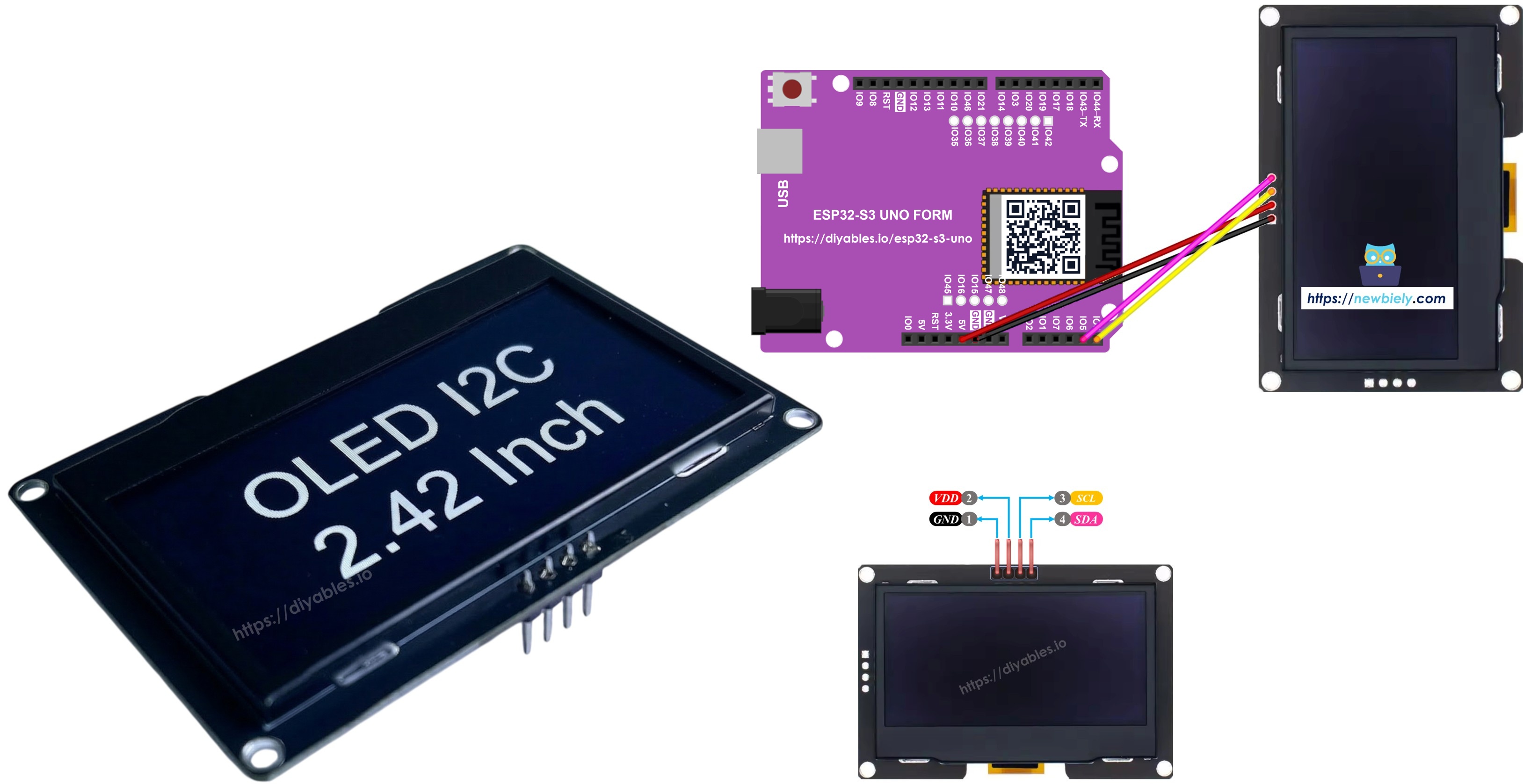
In this tutorial, you will:
- Wire a 2.42 inch SSD1309 I2C OLED to the SDA and SCL pins of the ESP32 S3 Uno
- Print text and numbers on a 128x64 OLED display
- Draw lines, rectangles, circles and triangles, and show bitmap images
- Use hardware scrolling and control the OLED contrast
- Use custom Adafruit GFX fonts on the screen
Hardware Preparation
| 1 | × | ESP32 S3 Uno-form Board | |
| 1 | × | USB Cable Type-A to Type-C (for USB-A PC) | |
| 1 | × | USB Cable Type-C to Type-C (for USB-C PC) | |
| 1 | × | SSD1309 I2C OLED Display 128x64 (2.42 inch) | |
| 1 | × | Jumper Wires |
Or you can buy the following kits:
| 1 | × | DIYables Sensor Kit (18 sensors/displays) |
Additionally, some of these links are for products from our own brand, DIYables .
Overview of the SSD1309 2.42-Inch OLED Display
Knowing a little about the driver chip helps you pick the right library and avoid wiring mistakes. It also explains why some code written for other OLED screens almost works, but not quite.
An OLED screen has no backlight. Each pixel makes its own light, so black areas are truly black, the contrast is very high, and you can read the screen from almost any angle. The SSD1309 is the driver chip that controls a 128×64 pixel OLED panel. Its command set is close to the popular SSD1306, so code moves between the two with only small changes.
How the SSD1309 differs from the SSD1306
The SSD1309 has no built-in charge pump, so the panel needs an outside VCC supply. You do not need to worry about this: ready-made 2.42 inch and 2.4 inch breakout boards carry their own boost circuit. The SSD1309 also accepts a much higher panel voltage, up to 16 V, while the SSD1306 stops at about 4.2 V.
Screen color
The color you see (white, blue, yellow, green, or a two-color layout) comes from the OLED glass itself. You cannot change it in code.
I2C interface
This tutorial talks to the display over the I2C bus. It needs only two signal wires, SDA and SCL, and other I2C modules can share the same two wires.
SSD1309 OLED Pinout (I2C Module)
A typical 2.42 inch SSD1309 I2C module has four pins. Here is what each one does.
| Pin | Function |
|---|---|
| GND | Ground, connect to a GND pin of the ESP32 S3 Uno |
| VCC | Power input for the module (5V on most boards, or 3.3V if your module supports it) |
| SCL | I2C clock line |
| SDA | I2C data line |
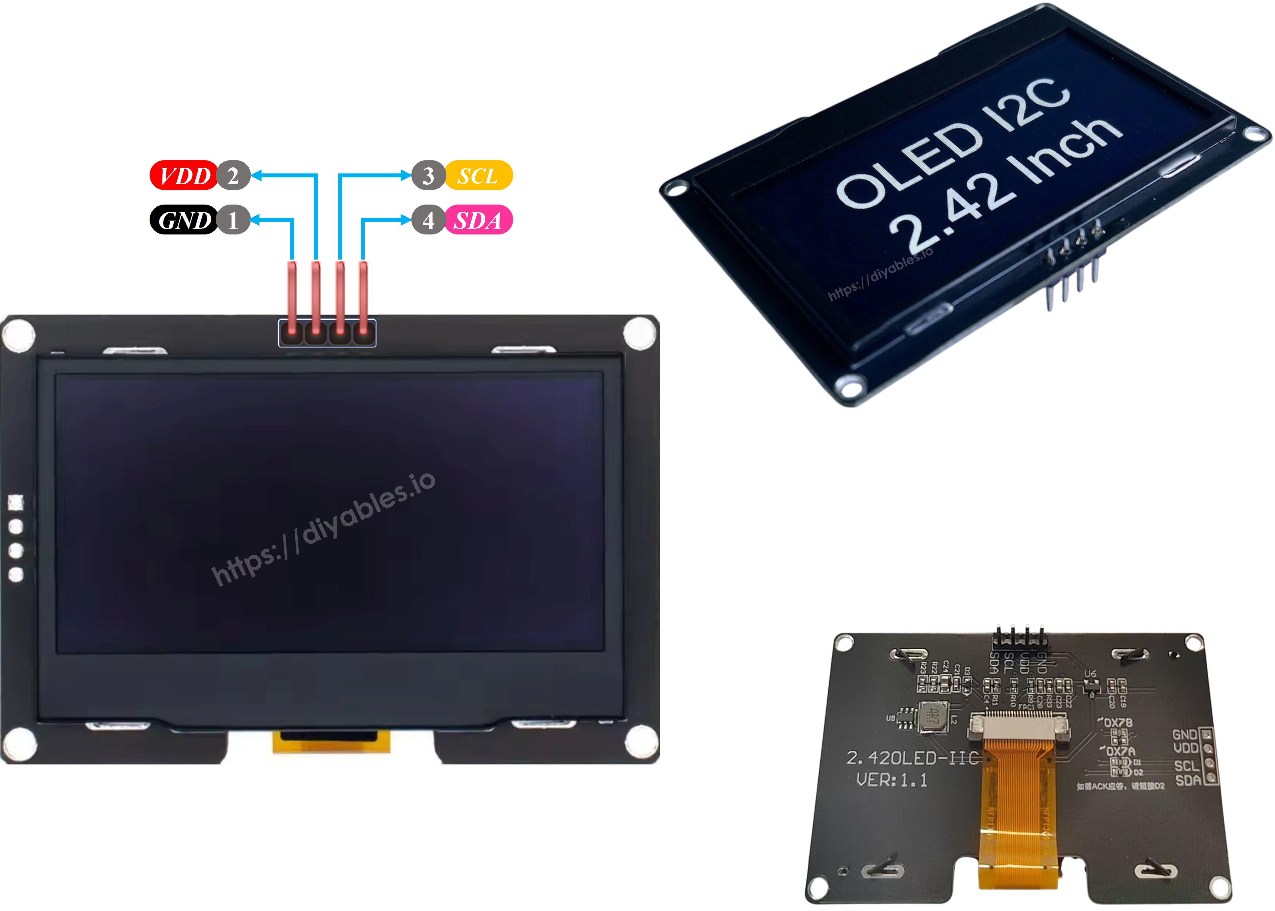
※ NOTE THAT:
- Pin order is not the same on every brand. Always read the labels printed on your module before you connect any wire.
- This guide was tested with the 2.42 inch SSD1309 OLED display from DIYables. Other 2.4/2.42 inch SSD1309 modules should work the same way.
ESP32 S3 Uno Pinout
The image below shows the pinout diagram of the ESP32 S3 Uno form board. Use it to find the SDA and SCL header pins and their GPIO numbers before you wire the OLED.

Wiring Diagram — ESP32 S3 Uno & SSD1309 OLED 128×64
On the ESP32 S3 Uno, the I2C bus is on the SDA (GPIO8) and SCL (GPIO9) header pins, not on A4 and A5 like on a classic Uno. The diagram and the photo below show the four wires you need.
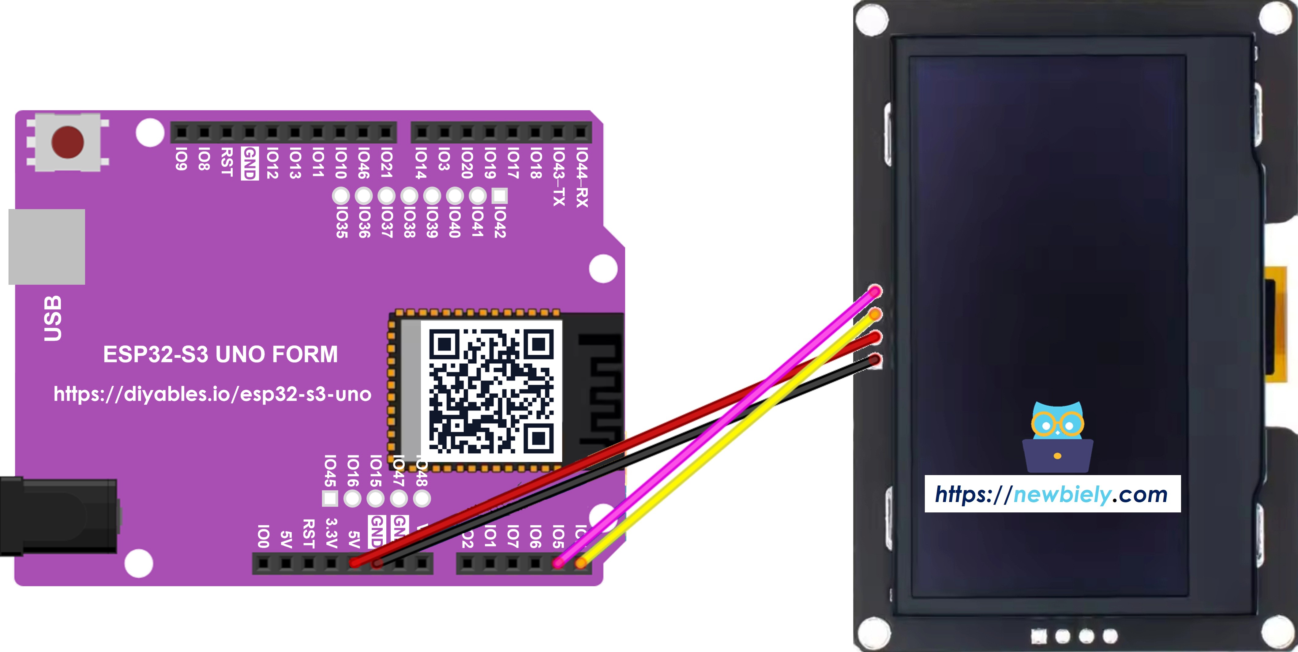
This image is created using Fritzing. Click to enlarge image
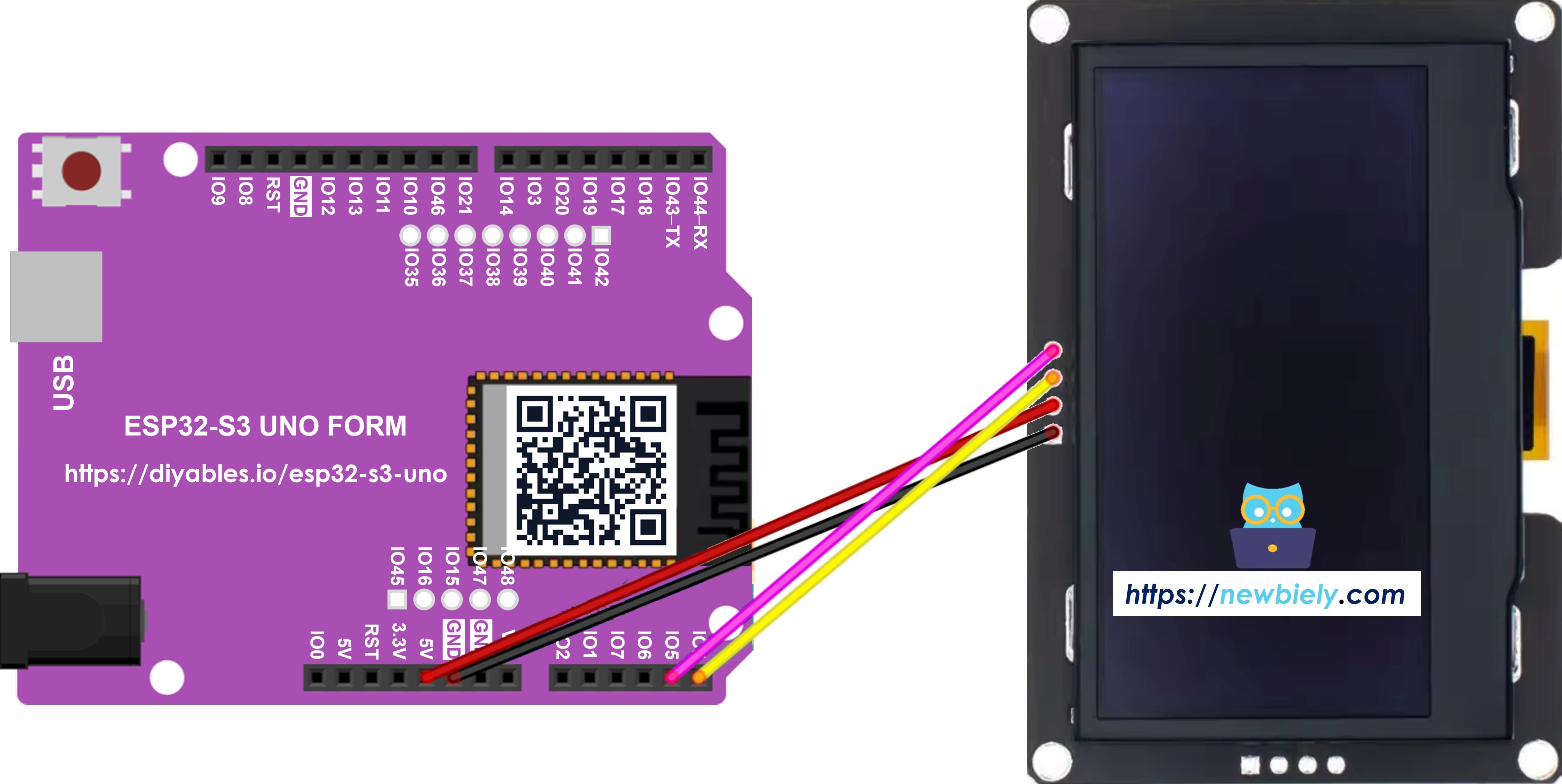
This image is created using Fritzing. Click to enlarge image
| OLED Module Pin | ESP32 S3 Uno Pin |
|---|---|
| VCC (Vin) | 5V |
| GND | GND |
| SDA | SDA (GPIO8) |
| SCL | SCL (GPIO9) |
WARNING
The ESP32 S3 Uno pins are 3.3V only and are NOT 5V tolerant. Most 2.42 inch SSD1309 modules have an onboard regulator, so their SDA and SCL lines stay at 3.3V even when VCC is 5V. If your module pulls SDA and SCL up to 5V, power it from the 3.3V pin instead (if the module supports it), or put an I2C level shifter between the module and the board.
※ NOTE THAT:
A4 and A5 are plain analog pins on the ESP32 S3 Uno. Do not wire the OLED to them. Wire.begin() uses GPIO8 (SDA) and GPIO9 (SCL) by default, so the code needs no pin settings.
Getting Started — SSD1309 OLED with ESP32 S3 Uno
Before you upload any example, you need the right library and a basic idea of how an OLED sketch is built. Every example in this tutorial follows the same pattern, so it pays to learn it once.
Step 1: Install the DIYables_OLED_SSD1309 Library
- Open the Library Manager — in Arduino IDE, click the Libraries icon on the left bar.
- Search — type "DIYables_OLED_SSD1309" and find the library made by DIYables.
- Install — click the Install button.
- Search for DIYables_OLED_SSD1309 created by DIYables and click the Install button.
- Add the dependency — Arduino IDE asks you to also install the Adafruit GFX Library. Click Install All.
Step 2: Basic Programming Structure
Every SSD1309 sketch does five things. It includes the headers, creates a display object, starts the display in setup(), draws into a memory buffer, and finally sends that buffer to the screen with display().
Include the headers
Set the screen size
The 2.42 inch module is 128 pixels wide and 64 pixels tall.
Create the display object
Pass -1 as the reset pin, because the module's reset line is not connected.
Start the display in setup()
After this, you call drawing functions such as clearDisplay(), drawPixel() or print(). Nothing shows on the screen until you call oled.display().
※ NOTE THAT:
Every code example in this guide is written for the SSD1309 OLED 128×64 (2.42 inch) with the DIYables_OLED_SSD1309 library, running on the ESP32 S3 Uno.
Quick Steps to run any example below
- New to the ESP32 S3 Uno? Follow ESP32 S3 Uno - Getting Started first.
- Wire it up as shown in the diagram above.
- Connect the board to your computer with a USB Type-C cable.
- Open Arduino IDE, choose the ESP32S3 Dev Module board and the correct COM port.
- Install the library as shown in Step 1, if you have not done it yet.
- Copy the code of the example and paste it into Arduino IDE.
- Upload — click the Upload button and wait for "Done uploading".
- Check the screen — the OLED shows the result a moment after the board restarts.
- Tip: if the screen stays dark, open the Serial Monitor at 9600 baud. A "SSD1309 allocation failed" message means the board cannot talk to the OLED, so check the wiring and the I2C address.
ESP32 S3 Uno Code — Hello World on SSD1309 OLED
Start with the simplest test. If this sketch works, your wiring, library and I2C address are all correct.
The code starts the display, prints "Hello, World!" in small text, then "DIYables" in a bigger size, and a short label at the bottom. Everything is drawn once in setup(), so loop() stays empty.
ESP32 S3 Uno Code — Display Text on SSD1309 OLED
Text is what most projects show, so it helps to see the options in one place. This example goes one step further than Hello World.
The sketch first shows two text sizes, one after the other. Then it clears the screen and prints an integer, a float and a hex number. The F() macro keeps fixed strings in flash memory instead of RAM.
Useful Display Functions Reference
Keep this list nearby when you write your own sketches. These are the SSD1309 functions you will use most with the DIYables library.
| Function | What it does |
|---|---|
| oled.clearDisplay() | Clears the buffer, all pixels off |
| oled.display() | Sends the buffer to the OLED so changes become visible |
| oled.drawPixel(x, y, color) | Turns one pixel on or off |
| oled.setTextSize(n) | Scales the font by n (1 = 6×8, 2 = 12×16, up to 8) |
| oled.setCursor(x, y) | Moves the text cursor to pixel (x, y) |
| oled.setTextColor(SSD1309_PIXEL_ON) | Text color only, with a see-through background |
| oled.setTextColor(SSD1309_PIXEL_OFF, SSD1309_PIXEL_ON) | Text color with a solid background |
| oled.println("message") | Prints a string and goes to the next line |
| oled.println(number) | Prints a number in decimal |
| oled.println(number, HEX) | Prints a number in hexadecimal |
| oled.startscrollright(start, stop) | Hardware scroll to the right from page start to page stop |
| oled.startscrollleft(start, stop) | Hardware scroll to the left |
| oled.startscrolldiagright(start, stop) | Hardware scroll diagonally to the right |
| oled.startscrolldiagleft(start, stop) | Hardware scroll diagonally to the left |
| oled.stopscroll() | Stops any running hardware scroll |
| oled.setContrast(value) | Sets the brightness (0 to 255) |
| oled.dim(true/false) | Dims to minimum, or goes back to the last contrast |
| oled.invertDisplay(true/false) | Swaps on and off pixels in hardware |
How to Vertically and Horizontally Center Text on the SSD1309 OLED
Centered text looks much cleaner on a small screen. The guide below shows how to measure the text and place it in the middle, and it works the same way on the ESP32 S3 Uno: How to vertical/horizontal center on OLED
ESP32 S3 Uno Code — Draw Shapes on SSD1309 OLED
Shapes let you build gauges, frames, icons and simple games. The DIYables_OLED_SSD1309 library is built on Adafruit_GFX, so you get all its drawing functions for free.
This sketch loops through pixels, lines, rectangles, circles, rounded rectangles and triangles. Each shape is drawn first as an outline and then filled with SSD1309_PIXEL_INVERSE, which flips the pixels and makes nice ring patterns. Every pattern stays on the screen for 1.5 seconds.
ESP32 S3 Uno Code — Hardware Scrolling on SSD1309 OLED
Scrolling text catches the eye, and the SSD1309 can do it by itself. The chip moves the picture, so your ESP32 S3 Uno code is free to do other work.
There are four scroll modes: right, left, diagonal right and diagonal left. Each one takes a start page and a stop page. A page is a band 8 pixels tall, and a 64-pixel screen has pages 0 to 7. The sketch below prints "DIYables" and then runs each mode for 3 seconds.
※ NOTE THAT:
Call display() to send your content to the OLED before you start a scroll. Do not draw new content while a scroll is running — call stopscroll() first.
ESP32 S3 Uno Code — Display Bitmap Image on SSD1309 OLED
A logo or an icon makes your project look finished. The OLED cannot read a PNG or JPG file, so you first turn the picture into a C byte array. The free image2cpp online tool does this for you:
- Upload your image (PNG, JPG, BMP and so on).
- Set the canvas size to 128×64 or smaller.
- Choose Arduino code as the output format.
- Copy the array it creates into your sketch.
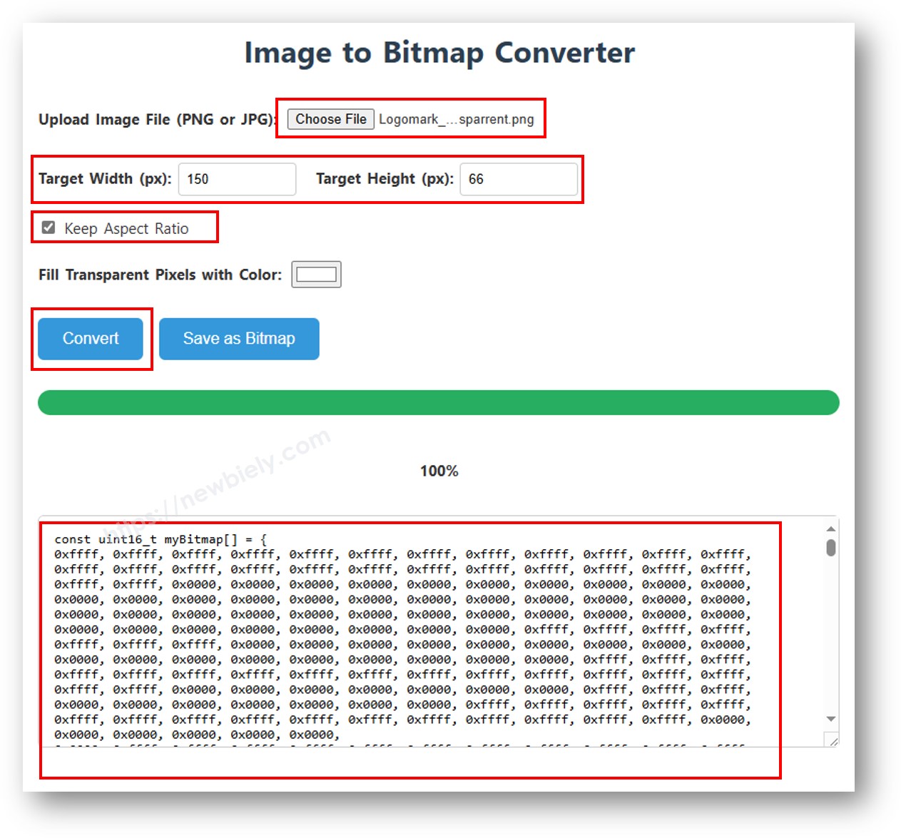
The example switches between a small 16×16 heart in the middle of the screen and a full-screen DIYables logo. After that, it inverts the whole display for 2 seconds.
※ NOTE THAT:
- The bitmap must not be bigger than the screen (128×64 for the 2.42 inch module).
ESP32 S3 Uno Code — Contrast and Dim on SSD1309 OLED
Brightness control saves power and keeps the screen easy to read in a dark room. The SSD1309 has 256 contrast steps, from 0 to 255.
The sketch draws a test pattern, then slowly raises the contrast to full and lowers it again with setContrast(). After that, it uses dim() to jump to the lowest brightness and back.
ESP32 S3 Uno Code — Custom External Fonts on SSD1309 OLED
The built-in font is small and blocky. For a nicer look, the Adafruit GFX library comes with many FreeFont typefaces: Serif, Sans and Mono, each in regular, bold and italic, in several sizes.
To use one, include its header file and call setFont(). The sketch below shows the built-in font first, then FreeSerif 9pt, FreeSansBold 12pt and FreeMono 9pt, each for 3 seconds. Call setFont(NULL) to go back to the built-in font.
※ NOTE THAT:
- With an external font, the cursor Y position is the text baseline, not the top-left corner. This is different from the built-in 5×7 font.
- External fonts are stored in flash memory. Small boards like the classic Uno (32 KB flash) run out of space fast, but the ESP32 S3 Uno has megabytes of flash, so you can use several fonts in one sketch.
SSD1309 OLED Diagnostics with ESP32 S3 Uno
A blank screen after upload is the most common problem with OLEDs. Go through these checks one by one.
Check the wiring
Make sure SDA goes to SDA (GPIO8), SCL goes to SCL (GPIO9), and VCC and GND are connected. On the ESP32 S3 Uno, A4 and A5 do not work for I2C.
Check the driver chip
This library is made for the SSD1309. A module with another chip, such as the SH1106, will not respond the right way.
Find the I2C address
Most SSD1309 modules use 0x3C, but some use 0x3D. Upload the I2C scanner sketch below and open the Serial Monitor at 9600 baud to see the real address.
When the OLED is found, the Serial Monitor shows something like this:
Call display()
The SSD1309 library draws into a buffer in RAM. Nothing shows on the screen until you call oled.display().
Check the power
The 2.42 inch module needs more current than small OLEDs, about 20–40 mA at full brightness. Use a good USB cable and port so the board gets enough power.
FAQ
Which ESP32 S3 Uno pins do I use for the SSD1309 I2C OLED?
Use the SDA (GPIO8) and SCL (GPIO9) header pins. On this board A4 and A5 are analog pins only, not I2C. Wire.begin() already uses GPIO8 and GPIO9, so you do not need to set the pins in code.
Can I power the 2.42 inch OLED from 5V on the ESP32 S3 Uno?
Yes, most 2.42 inch SSD1309 modules run from 5V and have their own regulator. The important part is the SDA and SCL voltage, because ESP32 S3 Uno pins are not 5V tolerant. If your module pulls these lines up to 5V, use 3.3V power (if the module supports it) or an I2C level shifter.
Does the same code work on the UNO R4 and the ESP32 S3 Uno?
Yes. The DIYables_OLED_SSD1309 library and the Adafruit GFX library work on both boards, and the example sketches are the same. Only the wiring changes: on the ESP32 S3 Uno, use the SDA and SCL header pins instead of A4 and A5.
Can I change the color of the SSD1309 OLED in code?
No. The color comes from the OLED panel itself (white, blue, yellow, green or two colors). The code can only turn each pixel on or off.
Can I connect other I2C sensors together with the OLED?
Yes. I2C is a shared bus, so you can connect more modules to the same SDA and SCL pins. Each device must have a different address. Run the I2C scanner to check that all of them show up.
What if my project needs more pins than the Uno headers give?
The ESP32 S3 Uno has two extra rows of holes with more GPIOs. GPIO15 and GPIO16 offer I/O, PWM and analog. GPIO45 and GPIO35–GPIO42 offer I/O and PWM. GPIO47 and GPIO48 are output only, with PWM. Solder pin headers to use them and write the GPIO number in code. For an OLED project, GPIO35–GPIO42 are good for extra buttons, and GPIO15/16 fit analog sensors. Be careful with two things. First, GPIO47 and GPIO48 may run at 1.8V instead of 3.3V on some modules (especially ones with "V" in the name, like R8V or R16V), so 3.3V devices can be damaged or act strangely. Second, GPIO0, GPIO3 (D6), GPIO45 and GPIO46 (D9) are boot strapping pins, and a wrong connection can stop the board from booting or uploading code. Use the other extra pins first.
Troubleshooting
| Problem | Possible Cause | Solution |
|---|---|---|
| No COM port in Arduino IDE | USB driver missing or board not in upload mode | Install the CP210x or CH340 driver, try another USB cable, or hold BOOT while you press RESET |
| Screen stays dark | OLED wired to A4/A5 or a loose wire | Connect SDA to SDA (GPIO8) and SCL to SCL (GPIO9), and check VCC and GND |
| "SSD1309 allocation failed" in Serial Monitor | Wrong I2C address or no I2C link | Run the I2C scanner and put the found address (0x3C or 0x3D) in SCREEN_ADDRESS |
| Code does not compile | DIYables_OLED_SSD1309 or Adafruit GFX library missing | Install both libraries from the Library Manager |
| Picture is garbled or shifted | The module uses another driver chip such as SH1106 | Check the chip on your module and use a library made for that chip |
| Screen flickers or resets | Weak USB power or long thin wires | Use a better USB port and cable, and keep the I2C wires short |
| Nothing changes after drawing | display() is not called | Call oled.display() after your drawing functions |
| Serial Monitor shows strange characters | Wrong baud rate | Set the Serial Monitor to 9600 baud |