
ESP32 S3 UNO - DC Motor Shield
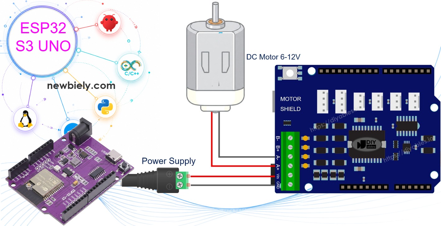
This ESP32 S3 Uno DC motor shield tutorial shows you how to stack the Motor Shield Rev3 on the ESP32 S3 Uno form board and drive DC motors with Arduino code. The shield is built around the L298P motor driver, so you can change speed with PWM, flip direction, brake, and read the motor current. Because the board has the classic Uno header layout, the shield plugs right on top.
In this tutorial, you will:
- Stack the Motor Shield Rev3 on the board and connect a DC motor and a battery pack.
- Spin the motor forward and backward with the DIYables_DC_Motor library.
- Set the motor speed with a PWM value from 0 to 255.
- Brake the motor and read its current draw on the 12-bit ADC.
- Drive two motors at once on Channel A and Channel B.
Hardware Preparation
Or you can buy the following kits:
| 1 | × | DIYables Sensor Kit (18 sensors/displays) |
Additionally, some of these links are for products from our own brand, DIYables .
Motor Shield Rev3 Overview
Before you write any code, it helps to know which pin does what on the shield. Every motor channel uses four pins, and the code must point to the right GPIO numbers.
The main chip on the Motor Shield Rev3 is the L298P dual full-bridge driver. It controls two DC motors on their own. Each motor channel has a direction line, a PWM speed line, a brake line, and a current-sensing output.
Direction
This is a digital output. HIGH spins the motor one way, and LOW spins it the other way.
PWM (Speed)
This is a PWM output. The value goes from 0 (stopped) to 255 (full speed).
Brake
This is a digital output. HIGH locks the motor shaft. LOW lets the motor turn freely.
Current Sensing
This is an analog signal that goes back into the ESP32 S3 Uno. Its voltage rises when the motor draws more current.
The ESP32 S3 Uno uses the same header positions as a classic Uno, so the shield pins land on these ESP32 S3 Uno pins:
| Function | Channel A | Channel B |
|---|---|---|
| Direction | D12 (GPIO13) | D13 (GPIO12) |
| PWM (Speed) | D3 (GPIO17) | D11 (GPIO11) |
| Brake | D9 (GPIO46) | D8 (GPIO21) |
| Current Sensing | A0 (GPIO2) | A1 (GPIO1) |
WARNING
The library shortcuts MOTOR_CH_A and MOTOR_CH_B store classic Uno pin numbers (12, 3, 9, A0...). On the ESP32 S3 Uno these numbers point to the wrong GPIOs. That is why every sketch in this tutorial passes the GPIO numbers to the constructor, for example DIYables_DC_Motor motor(13, 17, 46, 2);
Powering the Motors
A DC motor needs more current than the USB port can give. Connect a 6-12V external supply (for example two 18650 lithium cells in series) to the power screw terminals of the shield. The ESP32 S3 Uno can still run from USB.
※ NOTE THAT:
The shield has a "Vin Connect" jumper on its back. When it is closed, the motor supply also goes to the VIN pin of the ESP32 S3 Uno. Make sure your supply voltage is inside the VIN range of your board. If you are not sure, cut this jumper and power the board from USB.
ESP32 S3 Uno Pinout
The image below shows the pinout of the ESP32 S3 Uno form board. Use it to see which GPIO sits under each Uno header pin that the shield uses.

Wiring Diagram
There are no jumper wires for the control signals. You just stack the shield and connect the motor and the battery to the screw terminals.
- Push the Motor Shield Rev3 onto the ESP32 S3 Uno headers. Check that every pin goes in fully.
- Connect the two DC motor wires to the Channel A screw terminals. The channel names are printed on the shield.
- Connect the external battery pack to the power screw terminals.
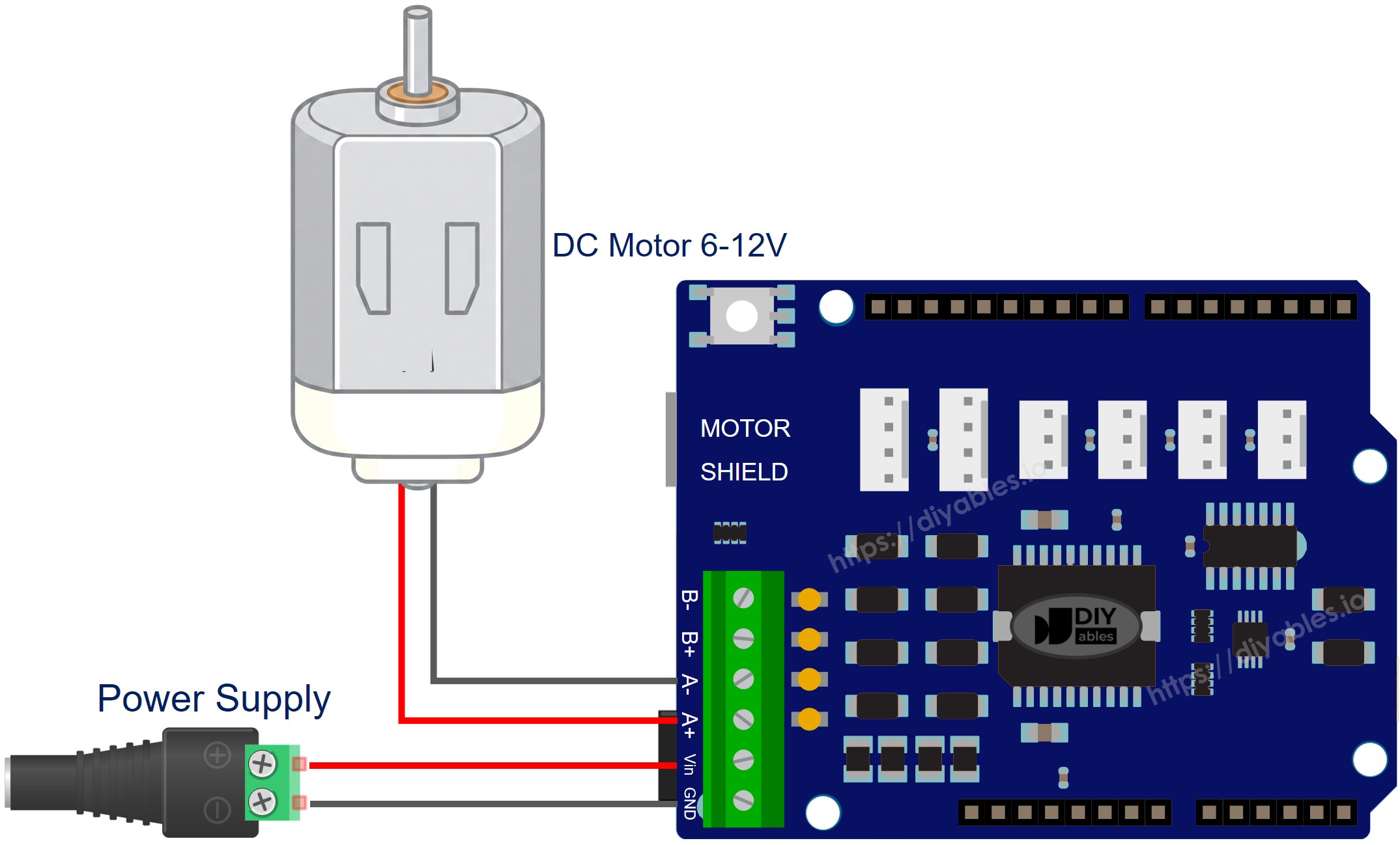
This image is created using Fritzing. Click to enlarge image
| Motor Shield Function | ESP32 S3 Uno Pin |
|---|---|
| Channel A Direction | D12 (GPIO13) |
| Channel A PWM | D3 (GPIO17) |
| Channel A Brake | D9 (GPIO46) |
| Channel A Current Sensing | A0 (GPIO2) |
| Channel B Direction | D13 (GPIO12) |
| Channel B PWM | D11 (GPIO11) |
| Channel B Brake | D8 (GPIO21) |
| Channel B Current Sensing | A1 (GPIO1) |
WARNING
Channel A Brake uses D9, which is GPIO46 on the ESP32 S3 Uno. GPIO46 is a boot strapping pin. The board reads it at power-up to choose the boot mode. In most cases the shield does not pull it HIGH, so the board starts normally. If the board does not boot or cannot upload code with the shield on, remove the shield, upload the code, and then put the shield back.
※ NOTE THAT:
All signals from the ESP32 S3 Uno to the shield are 3.3V outputs, which the shield accepts. The only signals that come back into the board are the current-sensing outputs on A0 and A1. They give about 1.65V per amp, so they stay under 3.3V up to the 2A limit of each channel. No 5V signal goes into an ESP32 S3 Uno pin.
How to Install the Library
The DIYables_DC_Motor library hides the pin details and gives you simple functions like run() and brake(). You only need to install it once.
- Connect the ESP32 S3 Uno to your computer with a USB Type-C cable.
- Open the Arduino IDE and select the ESP32S3 Dev Module board and the correct COM port.
- Click the Libraries icon on the left side.
- Type "DIYables_DC_Motor" in the search box and find the library by DIYables.
- Click Install.
- Search for DIYables_DC_Motor created by DIYables.io and click the Install button.
The library has no other dependencies, so nothing else needs to be installed.
Minimal Sketch Structure
Every motor sketch in this tutorial follows the same small pattern. Once you know it, the longer examples are easy to read.
The call to motor.begin() sets up the direction, PWM and brake pins. Then motor.run() sets the direction, releases the brake and applies the speed you ask for. Finally, motor.brake() locks the motor and sets the PWM to zero.
Single Motor on Channel A
This first full example is the best place to check that your shield, motor and battery all work. The motor turns forward, stops, turns backward, and stops again, every two seconds.
How to Run
- New to the ESP32 S3 Uno? Follow ESP32 S3 Uno - Getting Started first.
- Wire it up: stack the shield and connect the motor to Channel A.
- Connect the battery pack to the power screw terminals.
- Connect the board to your computer with a USB Type-C cable.
- Open Arduino IDE, choose the ESP32S3 Dev Module board and the correct COM port.
- Copy the code above and paste it into the Arduino IDE.
- Upload the code by clicking the Upload button.
- Open the Serial Monitor at 9600 baud to see the direction changes.
- Tip: if the motor only hums and does not turn, raise the speed value from 30 to 80 or more.
The motor switches between forward and backward at speed 30, with a 2-second stop between each change.
Method Quick Reference
| Method | What It Does | Usage |
|---|---|---|
| run(dir, speed) | Spins the motor in the given direction at the given speed | motor.run(MOTOR_FORWARD, 100) |
| setSpeed(speed) | Changes speed without touching direction or brake | motor.setSpeed(200) |
| setDirection(dir) | Changes direction without touching speed or brake | motor.setDirection(MOTOR_BACKWARD) |
| brake() | Engages the brake and drops speed to zero | motor.brake() |
| release() | Disengages the brake | motor.release() |
| readCurrent() | Returns the raw ADC value of the current-sensing pin | motor.readCurrent() |
Single Motor on Channel B
The second channel works in exactly the same way. Only the pin numbers in the constructor change.
How to Run
- Move the motor wires to the Channel B screw terminals.
- Upload the sketch and open the Serial Monitor.
The motor behaves just like on Channel A. The difference is only the pins: D13 (GPIO12), D11 (GPIO11), D8 (GPIO21) and A1 (GPIO1).
Two Motors - Both Channels
With two motors you can build a small robot car. This sketch shows the three basic moves: both forward, both backward, and one forward with one backward (turning on the spot).
How to Run
- Connect one motor to Channel A and the other motor to Channel B.
- Upload the sketch and open the Serial Monitor.
The sketch repeats the three moves with a short brake between each one.
Reading Motor Current
Reading the current tells you how hard the motor is working. A sudden jump often means the motor is stalled or blocked.
The sketch runs the motor forward at speed 100 and prints the raw current reading every 500 ms. The line analogSetAttenuation(ADC_11db) in setup() is important. By default, the ESP32 S3 Uno ADC can only measure a small voltage. The 11 dB setting lets the analog pin read the full range, from 0V up to about 3.3V. Without it, readings reach 4095 too early and the current values look wrong.
How to Run
- Connect a motor to Channel A.
- Upload the sketch and open the Serial Monitor.
- Watch the value, which updates every 500 ms. Gently slow the motor shaft with your fingers and the number goes up.
About Current Sensing
Pins A0 (GPIO2) and A1 (GPIO1) carry a voltage that grows with the current of Channel A and Channel B. The shield gives about 1.65V per amp. The readCurrent() function returns the raw ADC value. On the ESP32 S3 Uno this is a 12-bit number from 0 to 4095, where 4095 is about 3.3V. To get a rough current in milliamps, use: current (mA) = raw × 3300 / 4095 / 1.65. For example, a reading of 410 is about 330mV, which is about 200mA. The ESP32 S3 Uno ADC is not perfectly linear, so treat this as an estimate.
Custom Pin Assignment
You can also give your own pin numbers to the constructor. This is useful if you use a different motor driver board, or if you want to move a signal to another pin.
How to Run
- Change the pin numbers in the constructor to match your hardware. Always write the GPIO number (for example 13), not the header label (D12).
- Upload the code and check that the motor runs as expected.
Quick Motor Checks
These are the first things to check when the motor does not behave as you expect. The full Troubleshooting table at the end of the page covers more cases.
Motor does not move
Check that the motor wires sit tightly in the screw terminals. Also check that the motor channel matches the pins in your code. Channel A uses 13, 17, 46, 2 and Channel B uses 12, 11, 21, 1.
Motor hums but has no torque
Raise the speed value. A very low PWM value may not be enough to start the motor.
External supply is dead
Charge or replace the batteries, and check the polarity at the power terminals.
Direction is reversed
Swap the two motor wires at the screw terminal, or swap MOTOR_FORWARD and MOTOR_BACKWARD in the code.
Current reading is always zero
Use the 4-pin constructor that includes the current-sensing pin, such as motor(13, 17, 46, 2). The 3-pin constructor has no current-sensing pin.
ESP32 S3 Uno DC Motor Shield - Full Demo
Watch the video below to see this ESP32 S3 Uno project step by step.
Platform Support
The library uses only standard Arduino functions (pinMode, digitalWrite, analogWrite, analogRead), so it runs on the ESP32 S3 Uno with the esp32 by Espressif Systems core. The only thing you must change is the constructor: pass the GPIO numbers instead of MOTOR_CH_A or MOTOR_CH_B, because those shortcuts hold classic Uno pin numbers.
FAQ
Can I use the Motor Shield Rev3 on the ESP32 S3 Uno?
Yes. The ESP32 S3 Uno has the Uno header layout, so the shield plugs in directly. The board sends 3.3V control signals to the shield, which the L298P driver reads as HIGH. The only signals coming back are the current-sensing voltages, and they stay under 3.3V.
Why can't I use MOTOR_CH_A and MOTOR_CH_B on the ESP32 S3 Uno?
These shortcuts store classic Uno pin numbers such as 12, 3 and 9. On the ESP32 S3 Uno, code uses GPIO numbers, and GPIO12, GPIO3 and GPIO9 are not under D12, D3 and D9. Use motor(13, 17, 46, 2) for Channel A and motor(12, 11, 21, 1) for Channel B instead.
Why does the current sensing code call analogSetAttenuation(ADC_11db)?
It sets the ESP32 S3 Uno ADC input range to about 0-3.3V, so the full current-sensing signal maps to 0-4095. Without it the range is smaller and readings saturate early. The UNO R4 does not need this line, because it is ESP32-only. The shield output stays at 3.3V or less up to 2A per channel.
Is D9 (GPIO46) safe to use for the brake pin?
It works in most cases. GPIO46 is a boot strapping pin, so the board checks it at power-up. If the board will not boot or upload with the shield on, take the shield off, upload, then put it back. You could also cut the brake trace and use a free pin, but then the brake would need a jumper wire.
Can I power the motors from the ESP32 S3 Uno 5V pin?
It is not a good idea. Motors draw high current and create electrical noise, which can reset the board. Use an external 6-12V supply on the shield's power terminals, and keep the board on USB.
What if my robot needs more pins than the Uno headers give?
The ESP32 S3 Uno has two extra rows of holes with more GPIOs: GPIO15 and GPIO16 (I/O, PWM, analog), GPIO45 and GPIO35 to GPIO42 (I/O, PWM), and GPIO47/GPIO48 (output only, PWM). Solder pin headers to use them and write the GPIO number in code. With the motor shield on, they are handy for extra parts: GPIO15/GPIO16 for analog sensors, and GPIO35 to GPIO42 for buttons or ultrasonic sensors. Do not use GPIO47/GPIO48 for inputs. Be careful with two things. First, GPIO47/GPIO48 may run at 1.8V instead of 3.3V on some modules (especially ones with "V" in the name, like R8V or R16V), so 3.3V devices can be damaged or act strangely. Second, GPIO0, GPIO3 (D6), GPIO45 and GPIO46 (D9) are boot strapping pins, and a wrong connection can stop the board from booting or uploading code. Use the other extra pins first.
Troubleshooting
| Problem | Possible Cause | Solution |
|---|---|---|
| No COM port or upload fails | USB driver missing or board not in download mode | Install the CP210x or CH340 driver, or hold BOOT while pressing RESET, then upload again |
| Board does not boot with the shield on | GPIO46 (D9 brake pin) is pulled HIGH at power-up | Remove the shield, upload the code, then stack the shield again |
| Motor does not move | Motor wires loose or no external power | Tighten the screw terminals and connect a charged 6-12V supply to the shield |
| Motor does not move but Serial Monitor prints | Code uses MOTOR_CH_A or MOTOR_CH_B | Pass the GPIO numbers to the constructor, like motor(13, 17, 46, 2) |
| Motor hums but does not turn | Speed value too low | Raise the PWM value to 80 or more |
| Board resets when the motor starts | Motor noise or power drop | Power the motors from the external supply, not the board 5V pin, and keep wires short |
| Current reading stays at 4095 or looks wrong | ADC attenuation not set | Add analogSetAttenuation(ADC_11db) in setup() |
| Compile error DIYables_DC_Motor.h not found | Library not installed | Install DIYables_DC_Motor from the Library Manager |