
ESP32 S3 UNO - Electromagnetic Lock
This ESP32 S3 Uno electromagnetic lock tutorial shows you how to lock and unlock a door from Arduino code. A maglock (magnetic lock) needs 12V, so you will drive it through a relay connected to the ESP32 S3 Uno form board. When the sketch runs, the EM lock grabs its metal plate, then lets it go, every 5 seconds.
In this tutorial, you will:
- Learn how a magnetic lock works and what its two parts do
- Wire a maglock, a relay and a 12V power adapter to the ESP32 S3 Uno
- Upload Arduino code that locks and unlocks the door with digitalWrite()
- Find out how to fix common relay and maglock problems
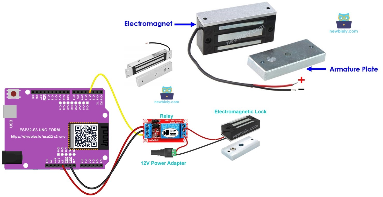
Hardware Preparation
| 1 | × | ESP32 S3 Uno-form Board | |
| 1 | × | USB Cable Type-A to Type-C (for USB-A PC) | |
| 1 | × | USB Cable Type-C to Type-C (for USB-C PC) | |
| 1 | × | Electromagnetic Lock | |
| 1 | × | Relay | |
| 1 | × | 12V Power Adapter | |
| 1 | × | DC Power Jack |
Or you can buy the following kits:
| 1 | × | DIYables Sensor Kit (18 sensors/displays) |
Additionally, some of these links are for products from our own brand, DIYables .
Overview of Electromagnetic Lock
An electromagnetic lock, or maglock, is a simple and strong way to keep a door shut. You will often see it at office entrances and gates. It usually works together with an access device, such as a switch, a fingerprint reader, an RFID/NFC reader, a keypad, or an app on a PC or phone.
Pinout
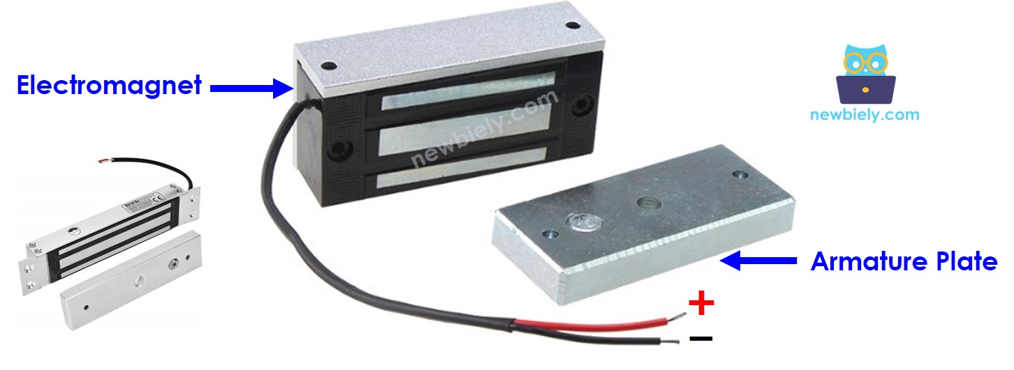
Knowing the two parts of the lock helps you mount it and wire it correctly. The first part is the electromagnet. It has two wires that go to the power circuit. The second part is the armature plate, a flat piece of metal with no wires at all.
How It Works
The idea is easy: power on means locked, power off means unlocked. When current flows through the electromagnet, it makes a magnetic field. This field pulls the armature plate hard against the magnet, and the door stays shut. When the current stops, the field disappears, and the plate can move away freely.
※ NOTE THAT:
Most electromagnetic locks run on 12V, 24V or 48V. An ESP32 S3 Uno pin gives only 3.3V and a few milliamps, so you can NOT connect the lock directly to it. Always switch the lock through a relay that is controlled by an ESP32 S3 Uno pin.
Using a Relay
In this project, the lock is wired to the relay in normally open mode. When the relay is open, no current reaches the lock, so the door is unlocked. When the relay is closed, the lock gets power, so the door is locked.
Your code controls the relay, and the relay controls the lock. If you have never used a relay before, read the ESP32 S3 Uno - Relay tutorial first.
Mounting the Lock
Put the armature plate on the part that moves, such as the door or window. Put the electromagnet on the part that stays still, such as the door frame. When the door is closed, the two parts must touch each other flat.
ESP32 S3 Uno Pinout
The image below shows the pinout diagram of the ESP32 S3 Uno form board. Use it to find the D3 header and its GPIO number when you wire the relay.

Wiring Diagram
The relay input side connects to the ESP32 S3 Uno, and the lock connects to the relay output together with the 12V power adapter. The control wire goes to D3.
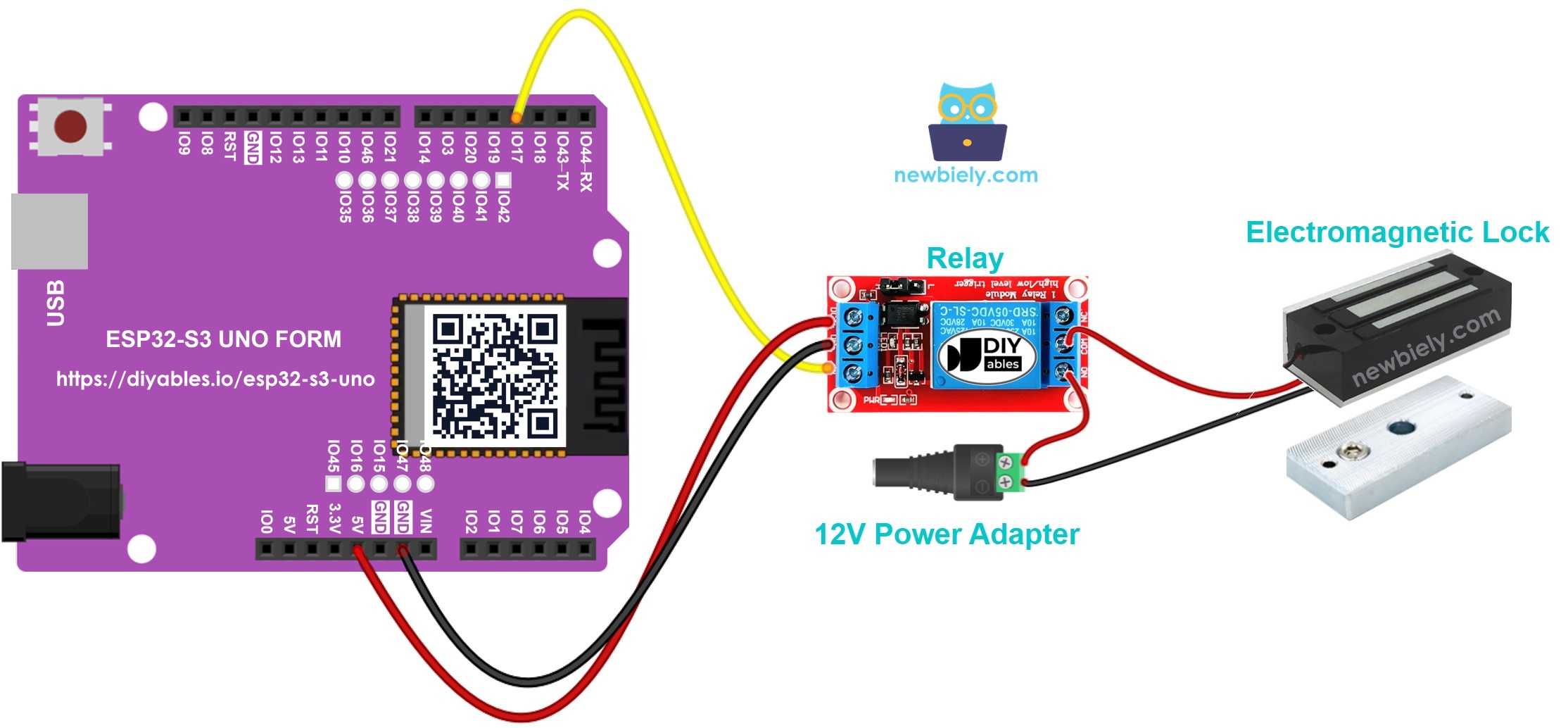
This image is created using Fritzing. Click to enlarge image
| Component Pin | ESP32 S3 Uno Pin |
|---|---|
| Relay DC+ (VCC) | 5V |
| Relay DC- (GND) | GND |
| Relay IN | D3 (GPIO17) |
※ NOTE THAT:
Most relay modules have a 5V coil, so power DC+ from the 5V pin. The IN pin only receives the 3.3V signal from the ESP32 S3 Uno, and most modules switch fine with it. The 12V adapter, the DC power jack and the lock connect to the COM and NO terminals of the relay. Never connect the 12V side to any ESP32 S3 Uno pin.
ESP32 S3 Uno Code
The sketch sets GPIO17 (D3) as an output. In the loop, it drives the relay HIGH to lock the door, waits 5 seconds, then drives it LOW to unlock the door and waits 5 seconds again.
Detailed Instructions
Follow these steps in order:
- New to the ESP32 S3 Uno? Follow ESP32 S3 Uno - Getting Started first.
- Wire it up as shown in the diagram.
- Connect the board to your computer with a USB Type-C cable.
- Open Arduino IDE, choose the ESP32S3 Dev Module board and the correct COM port.
- Copy the code above and paste it into Arduino IDE.
- Upload the code by clicking the Upload button.
- Hold the armature plate close to the electromagnet.
- Watch the lock. Every 5 seconds the plate is pulled in, then released.
- Tip: If the lock is on when it should be off, your relay may be a LOW level trigger module. Move its jumper to HIGH, or swap HIGH and LOW in the code.
Video Tutorial
Watch the video below to see this ESP32 S3 Uno project step by step.
FAQ
Can I power the electromagnetic lock from the ESP32 S3 Uno 5V pin?
No. A maglock needs 12V (or more) and a lot more current than the board can give. Use a separate 12V power adapter and let the relay switch it. The ESP32 S3 Uno only sends the control signal.
Will a 5V relay module work with the 3.3V ESP32 S3 Uno signal?
Most 5V relay modules switch fine with a 3.3V signal on the IN pin, because the input goes to a transistor or optocoupler. Power the module from the 5V pin. If your relay does not click, use a relay module rated for 3.3V logic.
Why is the door locked when the relay is HIGH?
The lock is wired in normally open mode. When IN is HIGH, the relay closes, the lock gets 12V and holds the plate. When IN is LOW, the relay opens and the door is free. Wire it to the NC terminal if you want the opposite.
What happens to the lock if the power goes out?
A maglock is "fail-safe": with no power, it can not hold the plate, so the door opens. This is good for fire exits, but it is not a high-security setup. Add a backup power supply if the door must stay locked.
Can I use the UNO R4 code on the ESP32 S3 Uno?
Yes, the logic is the same. Only the pin number changes. On the UNO R4 the relay pin is 3, but on the ESP32 S3 Uno the D3 header is GPIO17, so the code uses 17.
What if my project needs more pins than the Uno headers give?
The ESP32 S3 Uno has two extra rows of holes with more GPIOs: GPIO15 and GPIO16 (I/O, PWM, analog), GPIO45 and GPIO35 to GPIO42 (I/O, PWM), and GPIO47/GPIO48 (output only, PWM). Solder pin headers to use them and write the GPIO number in code. For extra relays or locks, GPIO35 to GPIO42 are a good choice; for buttons or keypads, avoid GPIO47/GPIO48 because they are output only. Be careful with two things. First, GPIO47 and GPIO48 may run at 1.8V instead of 3.3V on some modules (especially ones with "V" in the name, like R8V or R16V), so 3.3V devices can be damaged or act strangely. Second, GPIO0, GPIO3 (D6), GPIO45 and GPIO46 (D9) are boot strapping pins, and a wrong connection can stop the board from booting or uploading code. Use the other extra pins first.
Troubleshooting
| Problem | Possible Cause | Solution |
|---|---|---|
| No COM port in Arduino IDE | USB driver missing or board not in upload mode | Install the CP210x or CH340 driver, use a data USB cable, or hold BOOT while pressing RESET |
| Relay does not click | Relay not powered or IN wire on the wrong pin | Connect DC+ to 5V and DC- to GND, and check that IN goes to D3 (GPIO17) |
| Relay clicks but the lock does not hold | 12V adapter not connected or wired to the wrong terminals | Check the DC power jack polarity and wire the lock through COM and NO |
| Lock works in the opposite way | LOW level trigger relay or lock on the NC terminal | Set the relay jumper to HIGH trigger, move the wire to NO, or swap HIGH and LOW in code |
| Plate does not stick firmly | Plate and magnet not aligned or power too low | Mount the two parts flat against each other and use the voltage rated for your lock |
| Board resets when the lock switches | Electrical noise from the lock coil | Use a relay module with a flyback diode and keep the 12V wires away from the board |