
ESP32 S3 UNO - DIYables Bluetooth App Digital Pins

Overview

This ESP32 S3 Uno Bluetooth digital pins tutorial shows you how to switch output pins and watch input pins from your smartphone. The ESP32 S3 Uno form board talks to the free DIYables Bluetooth STEM app over BLE (Bluetooth Low Energy), so remote GPIO control works on both Android and iOS. You tap a pin in the app to turn it HIGH or LOW, and button or sensor values show up in real time.

In this tutorial, you will:

  1. Install the DIYables Bluetooth library in the Arduino IDE
  2. Control output pins (LED, relay) from your phone over BLE
  3. Monitor digital and analog input pins in real time
  4. Give each pin a friendly name in the app
  5. Learn which ESP32 S3 Uno pins the Bluetooth pin control app can use

※ NOTE THAT:

The ESP32 S3 Uno has BLE only. It has no Bluetooth Classic, so the BluetoothSerial version of this example does not run on this board. This page uses the BLE version only, which also has the bonus of working on iPhone.
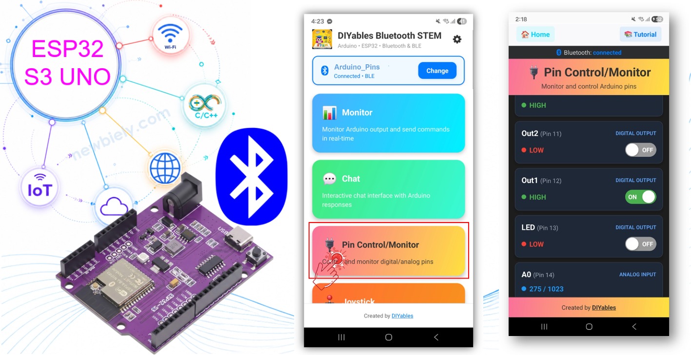
ESP32 S3 Uno Bluetooth digital pins

Features

The Digital Pins app turns your phone into a small control panel for the board. Here is what it gives you.

Output control

Tap an output pin in the app to switch it HIGH or LOW. This is all you need to drive an LED, a relay module or a buzzer.

Input monitoring

Digital inputs (buttons, switches, door sensors) and analog inputs (potentiometers, light sensors) appear in the app with their current value.

Custom pin names

Each pin can carry a short label such as "LED", "Btn1" or "A0", so you do not have to remember GPIO numbers.

Real-time updates

The sketch pushes a new value to the app as soon as an input changes. Up to 16 pins can be shown at once, and you can mix inputs and outputs.

Android and iOS

BLE works on both phone systems, and no manual pairing is needed.

Hardware Preparation

1×ESP32 S3 Uno-form Board
1×USB Cable Type-A to Type-C (for USB-A PC)
1×USB Cable Type-C to Type-C (for USB-C PC)
1×Breadboard
1×Jumper Wires

Or you can buy the following kits:

1×DIYables Sensor Kit (18 sensors/displays)
Disclosure: Some of the links provided in this section are Amazon affiliate links. We may receive a commission for any purchases made through these links at no additional cost to you.
Additionally, some of these links are for products from our own brand, DIYables .

ESP32 S3 Uno Pinout

The image below shows the pinout diagram of the ESP32 S3 Uno form board. Use it to find each Uno header pin (D7, D13, A0…) and its GPIO number when you connect LEDs, buttons or sensors.

ESP32 S3 Uno pinout diagram

ESP32 S3 Uno Code

The example runs without any extra parts, but it is more fun with an LED on D13 and a button on D7. The steps below install the library, upload the BLE sketch and check that it starts.

Detailed Instructions

  1. New to the ESP32 S3 Uno? Follow ESP32 S3 Uno - Getting Started first.
  2. Wire it up (optional): connect parts to the pins listed in the table below. The board has no built-in LED on D13, so add an external LED with a 220Ω resistor if you want to see the "LED" output change.
  3. Connect the board to your computer with a USB Type-C cable.
  4. Open Arduino IDE, choose the ESP32S3 Dev Module board and the correct COM port.
  5. Set the partition scheme: go to Tools > Partition Scheme and pick "Huge APP (3MB No OTA/1MB SPIFFS)". The Bluetooth stack is large and may not fit in the default app space.
  6. Open the Library Manager by clicking the Libraries icon on the left bar of the Arduino IDE.
  7. Search for the library: type "DIYables Bluetooth" and find the DIYables Bluetooth library by DIYables.
  8. Install it by clicking the Install button.
  • Search for DIYables Bluetooth created by DIYables and click the Install button.
∞
Newbiely | Arduino IDE 2.3.8
──
☐
✕
File
Edit
Sketch
Tools
Help
ESP32S3 Dev Module
Library Manager
Type:
All
Topic:
All
DIYables Bluetooth by DIYables
A comprehensive Bluetooth library that connects Arduino to the DIYables Bluetooth STEM mobile app (Android & iOS) via BLE and Classic Bluetooth. Features 11 built-in apps: Monitor, Chat, Digital Pin Control, Joystick, Sliders, Plotter, Analog Gauge, Rotator, Temperature, RTC, and Data Table. Clean architecture with platform abstraction. Works with Arduino Uno R4 WiFi, Arduino Nano 33 BLE, ESP32, and other BLE-capable boards. No mobile coding required. More info
1.0.1
INSTALL
Newbiely.ino
···
1 void setup() {
Output
Serial Monitor
Ln 1, Col 1
ESP32S3 Dev Module on COM15
1
  1. Install the dependencies: the IDE asks about other required libraries. Click Install All.
  2. Tip: if the upload ever stops at "Connecting...", hold the BOOT button, press RESET, then release BOOT and upload again.

Pins Used by the Example

The sketch enables seven pins in the app. The app shows the GPIO number of each pin, so this table helps you find the matching Uno header pin on the board.

App Name Mode ESP32 S3 Uno Pin
LED Output D13 (GPIO12)
Out1 Output D12 (GPIO13)
Out2 Output D11 (GPIO11)
Btn1 Input (pull-up) D7 (GPIO14)
Btn2 Input (pull-up) D6 (GPIO3)
A0 Analog input A0 (GPIO2)
A1 Analog input A1 (GPIO1)

WARNING

D6 (GPIO3) is a boot strapping pin on the ESP32 S3 Uno. Using it as a button input with the internal pull-up is normally fine. Do not tie it hard to 3.3V or GND with an external part while the board powers up, because that can change how the chip boots.

ESP32 S3 Uno BLE Code (works with the app on Android and iOS)

The sketch starts a BLE server named "ESP32BLE_Pins" and adds the Digital Pins app to it. When you tap a pin in the app, the onPinWrite() callback calls digitalWrite(). Every 100 ms the loop checks the two buttons and the two analog pins, and sends a new value to the app when something changes.

  1. Get the code: in the Arduino IDE, go to File Examples DIYables Bluetooth Esp32BLE_PinControl, or copy the ESP32 S3 Uno code below into the editor. The code below already uses the ESP32 S3 Uno pins from the table above.
/* * This ESP32 S3 Uno code was developed by newbiely.com * * This ESP32 S3 Uno code is made available for public use without any restriction * * For comprehensive instructions and wiring diagrams, please visit: * https://newbiely.com/tutorials/esp32-s3-uno/esp32-s3-uno-diyables-bluetooth-app-digital-pins */ /* * DIYables Bluetooth Library - ESP32 S3 Uno BLE Pin Control/Monitor Example * Works with DIYables Bluetooth STEM app on Android and iOS * * This example demonstrates the Bluetooth Pin Control/Monitor feature: * - Control digital output pins via Bluetooth * - Monitor digital input pins * - Monitor analog input pins * - Configure pin modes (INPUT/OUTPUT) * * Board: ESP32 S3 Uno (Arduino IDE board: "ESP32S3 Dev Module") * The ESP32 S3 Uno supports BLE only (no Classic Bluetooth). * * Note: Select "Huge APP (3MB No OTA/1MB SPIFFS)" partition scheme * in Arduino IDE: Tools > Partition Scheme * * Setup: * 1. Upload the sketch to your ESP32 S3 Uno * 2. Open Serial Monitor (115200 baud) to see connection status * 3. Use DIYables Bluetooth App to connect and control pins * * Tutorial: https://diyables.io/bluetooth-app * Author: DIYables */ #include <DIYables_BluetoothServer.h> #include <DIYables_BluetoothPinControl.h> #include <platforms/DIYables_Esp32BLE.h> // BLE Configuration const char* DEVICE_NAME = "ESP32BLE_Pins"; const char* SERVICE_UUID = "19B10000-E8F2-537E-4F6C-D104768A1214"; const char* TX_UUID = "19B10001-E8F2-537E-4F6C-D104768A1214"; const char* RX_UUID = "19B10002-E8F2-537E-4F6C-D104768A1214"; // Create Bluetooth instances DIYables_Esp32BLE bluetooth(DEVICE_NAME, SERVICE_UUID, TX_UUID, RX_UUID); DIYables_BluetoothServer bluetoothServer(bluetooth); // Create Pin Control/Monitor app instance DIYables_BluetoothPinControl bluetoothPins; // Pin configuration (ESP32 S3 Uno GPIOs) // The app accepts pin numbers 0-15 only, so all pins below are GPIO 0-15 const int LED_PIN = 12; // D13 (GPIO12) - external LED, no built-in LED on D13 const int OUTPUT_PIN_1 = 13; // D12 (GPIO13) const int OUTPUT_PIN_2 = 11; // D11 (GPIO11) const int INPUT_PIN_1 = 14; // D7 (GPIO14) const int INPUT_PIN_2 = 3; // D6 (GPIO3) - boot strapping pin const int ANALOG_PIN_1 = 2; // A0 (GPIO2) const int ANALOG_PIN_2 = 1; // A1 (GPIO1) void setup() { Serial.begin(115200); // set the ADC attenuation to 11 dB (up to ~3.3V input) analogSetAttenuation(ADC_11db); delay(1000); Serial.println("DIYables Bluetooth - ESP32 S3 Uno BLE Pin Control/Monitor Example"); // Initialize pins pinMode(LED_PIN, OUTPUT); pinMode(OUTPUT_PIN_1, OUTPUT); pinMode(OUTPUT_PIN_2, OUTPUT); pinMode(INPUT_PIN_1, INPUT_PULLUP); pinMode(INPUT_PIN_2, INPUT_PULLUP); // Initialize Bluetooth server with platform-specific implementation bluetoothServer.begin(); // Add digital pins app to server bluetoothServer.addApp(&bluetoothPins); // Configure which pins are accessible via Bluetooth with custom names bluetoothPins.enablePin(LED_PIN, BT_PIN_OUTPUT, "LED"); bluetoothPins.enablePin(OUTPUT_PIN_1, BT_PIN_OUTPUT, "Out1"); bluetoothPins.enablePin(OUTPUT_PIN_2, BT_PIN_OUTPUT, "Out2"); bluetoothPins.enablePin(INPUT_PIN_1, BT_PIN_INPUT, "Btn1"); bluetoothPins.enablePin(INPUT_PIN_2, BT_PIN_INPUT, "Btn2"); bluetoothPins.enablePin(ANALOG_PIN_1, BT_PIN_INPUT, "A0"); bluetoothPins.enablePin(ANALOG_PIN_2, BT_PIN_INPUT, "A1"); // Set up connection event callbacks bluetoothServer.setOnConnected([]() { Serial.println("Bluetooth connected!"); }); bluetoothServer.setOnDisconnected([]() { Serial.println("Bluetooth disconnected!"); }); // Set up callback for pin write commands bluetoothPins.onPinWrite([](int pin, int state) { digitalWrite(pin, state); Serial.print("Pin "); Serial.print(pin); Serial.print(" set to "); Serial.println(state ? "HIGH" : "LOW"); }); // Set up callback for pin read commands bluetoothPins.onPinRead([](int pin) -> int { int state; if (pin == ANALOG_PIN_1 || pin == ANALOG_PIN_2) { state = analogRead(pin); Serial.print("Analog pin "); Serial.print(pin); Serial.print(" read: "); Serial.println(state); } else { state = digitalRead(pin); Serial.print("Digital pin "); Serial.print(pin); Serial.print(" read: "); Serial.println(state ? "HIGH" : "LOW"); } return state; }); // Set up callback for pin mode changes bluetoothPins.onPinModeChange([](int pin, int mode) { pinMode(pin, mode == BT_PIN_OUTPUT ? OUTPUT : INPUT_PULLUP); Serial.print("Pin "); Serial.print(pin); Serial.print(" mode changed to "); Serial.println(mode == BT_PIN_OUTPUT ? "OUTPUT" : "INPUT"); }); Serial.println("Waiting for Bluetooth connection..."); Serial.print("Enabled pins: "); Serial.println(bluetoothPins.getEnabledPinCount()); } void loop() { bluetoothServer.loop(); static unsigned long lastInputCheck = 0; static int lastInputState1 = HIGH; static int lastInputState2 = HIGH; static int lastAnalogState1 = 0; static int lastAnalogState2 = 0; if (millis() - lastInputCheck >= 100) { lastInputCheck = millis(); int currentState1 = digitalRead(INPUT_PIN_1); if (currentState1 != lastInputState1) { lastInputState1 = currentState1; bluetoothPins.updatePinState(INPUT_PIN_1, currentState1); Serial.print("Input pin "); Serial.print(INPUT_PIN_1); Serial.print(" changed to "); Serial.println(currentState1 ? "HIGH" : "LOW"); } int currentState2 = digitalRead(INPUT_PIN_2); if (currentState2 != lastInputState2) { lastInputState2 = currentState2; bluetoothPins.updatePinState(INPUT_PIN_2, currentState2); Serial.print("Input pin "); Serial.print(INPUT_PIN_2); Serial.print(" changed to "); Serial.println(currentState2 ? "HIGH" : "LOW"); } // ESP32 S3 Uno has a 12-bit ADC (0-4095) int currentAnalog1 = analogRead(ANALOG_PIN_1); if (abs(currentAnalog1 - lastAnalogState1) > 40) { // ~1% of 4095 lastAnalogState1 = currentAnalog1; bluetoothPins.updatePinState(ANALOG_PIN_1, currentAnalog1); Serial.print("Analog pin "); Serial.print(ANALOG_PIN_1); Serial.print(" changed to "); Serial.println(currentAnalog1); } int currentAnalog2 = analogRead(ANALOG_PIN_2); if (abs(currentAnalog2 - lastAnalogState2) > 40) { lastAnalogState2 = currentAnalog2; bluetoothPins.updatePinState(ANALOG_PIN_2, currentAnalog2); Serial.print("Analog pin "); Serial.print(ANALOG_PIN_2); Serial.print(" changed to "); Serial.println(currentAnalog2); } } delay(10); }
  1. Upload the code by clicking the Upload button in the Arduino IDE.
  2. Open the Serial Monitor and set it to 115200 baud. You should see:
∞
Newbiely | Arduino IDE 2.3.8
──
☐
✕
File
Edit
Sketch
Tools
Help
ESP32S3 Dev Module
Newbiely.ino
···
8 Serial.println("Hello World!");
Output
Serial Monitor
Message (Enter to send message to 'ESP32S3 Dev Module' on 'COM15')
New Line
9600 baud
DIYables Bluetooth - ESP32 S3 Uno BLE Pin Control/Monitor Example Waiting for Bluetooth connection... Enabled pins: 7
Ln 11, Col 1
ESP32S3 Dev Module on COM15
2

The sketch calls analogSetAttenuation(ADC_11db) in setup(). By default, the ESP32 S3 Uno ADC can only measure a small voltage. The 11 dB setting lets A0 and A1 read the full range, from 0V up to about 3.3V. Without it, the readings hit 4095 too early and the values in the app look wrong.

Mobile App

The phone side needs no coding. You install the app, give it Bluetooth permission and connect to the board.

  1. Install the app on your smartphone: Android | iOS
  2. No pairing needed: the ESP32 S3 Uno uses BLE, so you do not pair it in the phone's Bluetooth settings. Just go to the next step.
  3. Open the DIYables Bluetooth App.
  4. Grant permissions the first time the app opens:
  • Nearby Devices permission (Android 12+) / Bluetooth permission (iOS) - needed to scan for and connect to Bluetooth devices
  • Location permission (Android 11 and below only) - older Android versions need it to scan for BLE devices
  1. Turn on Bluetooth on your phone.
  2. Scan: on the home screen, tap the Connect button.
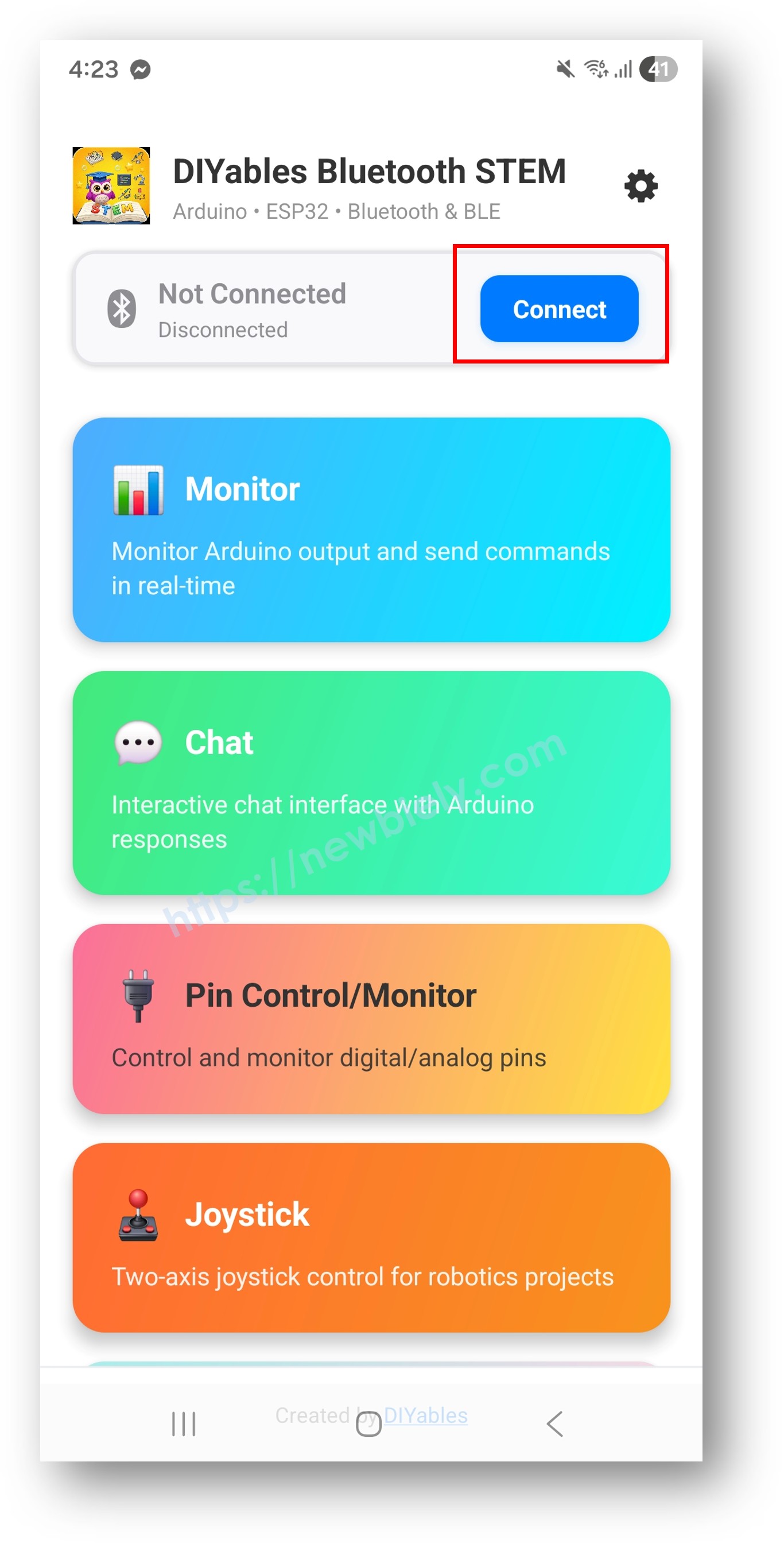
DIYables Bluetooth App - Home Screen with Scan Button
  1. Connect: tap "ESP32BLE_Pins" in the scan results.
  2. Open Digital Pins: after connecting, the app returns to the home screen. Choose the Digital Pins app from the menu.
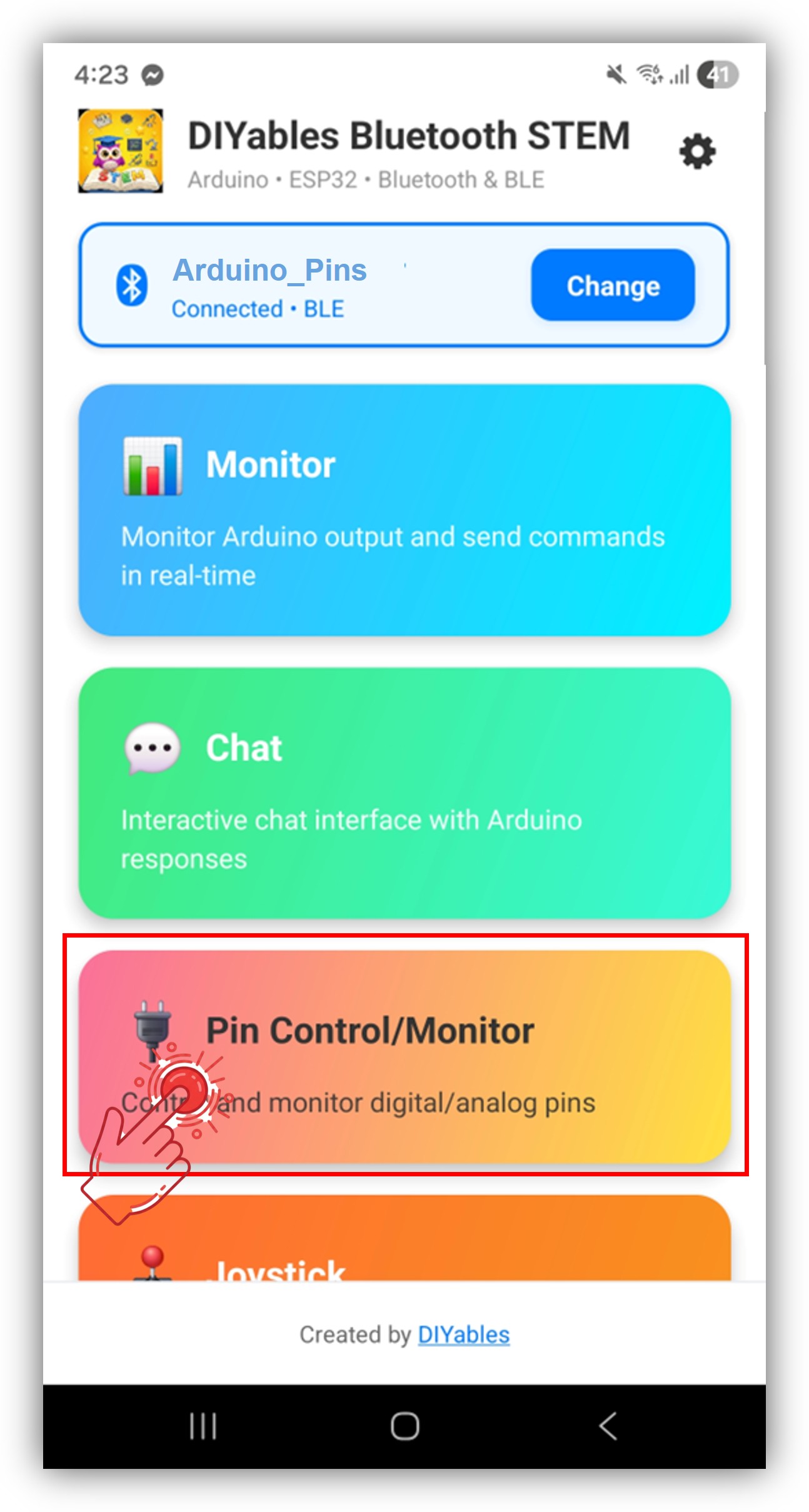
DIYables Bluetooth App - Home Screen with Digital Pins App

※ NOTE THAT:

You can tap the settings icon on the home screen to show or hide apps. For more details, see the DIYables Bluetooth App User Manual.

  1. Test it: tap the output pins to switch them, press a button on D7 or turn a potentiometer on A0, and watch the values change.
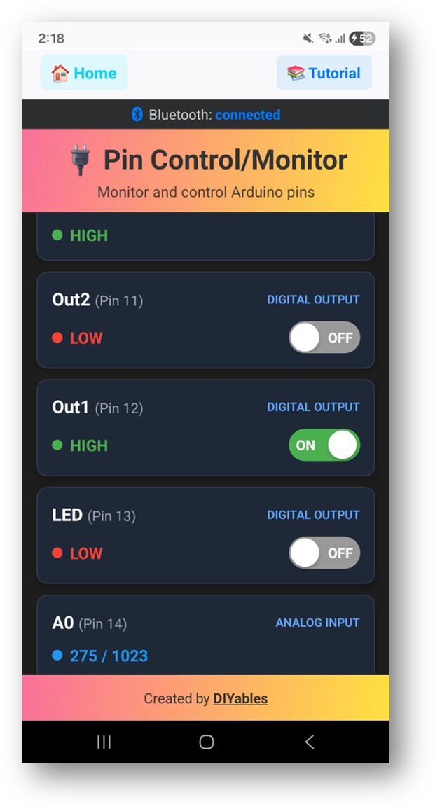
DIYables Bluetooth App - Digital Pins Screen
  1. Tip: check the Serial Monitor in the Arduino IDE at the same time. Each tap and each input change is logged there:
∞
Newbiely | Arduino IDE 2.3.8
──
☐
✕
File
Edit
Sketch
Tools
Help
ESP32S3 Dev Module
Newbiely.ino
···
8 Serial.println("Hello World!");
Output
Serial Monitor
Message (Enter to send message to 'ESP32S3 Dev Module' on 'COM15')
New Line
9600 baud
Bluetooth connected! Pin 12 set to HIGH Pin 12 set to LOW Input pin 14 changed to LOW Analog pin 2 changed to 2048
Ln 11, Col 1
ESP32S3 Dev Module on COM15
2

The numbers are GPIO numbers: pin 12 is D13, pin 14 is D7 and pin 2 is A0.

Creative Customization - Adapt the Code to Your Project

The example is a starting point. The short code parts below show how to choose your own pins, react to taps and push new values to the app.

WARNING

The Digital Pins app accepts pin numbers 0 to 15 only. A call like enablePin(21, ...) is ignored without any error. On the ESP32 S3 Uno, D2 (GPIO18), D3 (GPIO17), D4 (GPIO19), D5 (GPIO20), D8 (GPIO21) and D9 (GPIO46) are above 15. To use them, give the app a number from 0 to 15 and convert it to the real GPIO in your callbacks, as the demo sketch in the video section does.

Configure Pins

Call enablePin() once for each pin, with its mode and a short name. You can also turn a pin off again or ask how many pins are active.

// Enable individual pins with mode and custom name (GPIO numbers) bluetoothPins.enablePin(12, BT_PIN_OUTPUT, "LED"); // D13 (GPIO12) - external LED bluetoothPins.enablePin(13, BT_PIN_OUTPUT, "Relay1"); // D12 (GPIO13) - relay control bluetoothPins.enablePin(11, BT_PIN_OUTPUT, "Relay2"); // D11 (GPIO11) - relay control bluetoothPins.enablePin(14, BT_PIN_INPUT, "Button"); // D7 (GPIO14) - button input bluetoothPins.enablePin(2, BT_PIN_INPUT, "Sensor"); // A0 (GPIO2) - analog sensor // Disable a specific pin bluetoothPins.disablePin(11); // Check pin status bool isEnabled = bluetoothPins.isPinEnabled(12); int mode = bluetoothPins.getPinMode(12); int count = bluetoothPins.getEnabledPinCount();

Handle Pin Write Commands

The onPinWrite() callback runs every time you tap an output pin in the app. Put your hardware action inside it.

bluetoothPins.onPinWrite([](int pin, int state) { digitalWrite(pin, state); Serial.print("Pin "); Serial.print(pin); Serial.print(" set to "); Serial.println(state ? "HIGH" : "LOW"); });

Handle Pin Read Commands

When the app asks for a value, onPinRead() returns it. Use analogRead() for the analog pins and digitalRead() for the rest.

bluetoothPins.onPinRead([](int pin) -> int { if (pin == 2 || pin == 1) { // Read analog value for A0 (GPIO2) and A1 (GPIO1), range 0-4095 return analogRead(pin); } else { // Read digital value for other pins return digitalRead(pin); } });

Handle Pin Mode Changes

The app can switch a pin between input and output. The onPinModeChange() callback applies that change to the hardware.

bluetoothPins.onPinModeChange([](int pin, int mode) { pinMode(pin, mode == BT_PIN_OUTPUT ? OUTPUT : INPUT_PULLUP); Serial.print("Pin "); Serial.print(pin); Serial.print(" mode changed to "); Serial.println(mode == BT_PIN_OUTPUT ? "OUTPUT" : "INPUT"); });

Send Real-Time Pin State Updates

Call updatePinState() from loop() when an input changes. For analog pins, send an update only when the value moves by more than a small amount, so you do not flood the BLE link.

// Detect input changes and send updates int currentState = digitalRead(14); // D7 (GPIO14) if (currentState != lastState) { lastState = currentState; bluetoothPins.updatePinState(14, currentState); } // Send analog value updates (12-bit ADC, 0-4095) int analogValue = analogRead(2); // A0 (GPIO2) if (abs(analogValue - lastAnalogValue) > 50) { lastAnalogValue = analogValue; bluetoothPins.updatePinState(2, analogValue); }

Handle Connection Events

These two callbacks tell you when the phone connects or leaves. Turning all outputs off on disconnect is a good safety habit.

bluetoothServer.setOnConnected([]() { Serial.println("Bluetooth connected!"); }); bluetoothServer.setOnDisconnected([]() { Serial.println("Bluetooth disconnected!"); // Safety: turn off all outputs when disconnected digitalWrite(12, LOW); // D13 (GPIO12) digitalWrite(13, LOW); // D12 (GPIO13) digitalWrite(11, LOW); // D11 (GPIO11) });

How to Use the Digital Pins

Once connected, the app screen is simple. It helps to know what each part shows before you build a bigger project.

App interface

The pin list shows every enabled pin with its name and current state. Tap an output pin to toggle it between HIGH and LOW. Input pins update by themselves, and analog pins show the raw ADC number from 0 to 4095.

Pin modes

BT_PIN_OUTPUT (0) makes a pin an output that you control from the app. BT_PIN_INPUT (1) makes it an input that the app only displays.

Programming Examples

These three examples show common ways to use the app. All pin numbers are ESP32 S3 Uno GPIO numbers from 0 to 15, so the app accepts them directly.

Basic Relay Control

Four relay modules on D12, D11, D10 and D13 become four on/off switches in the app.

const int RELAY_1 = 13; // D12 (GPIO13) const int RELAY_2 = 11; // D11 (GPIO11) const int RELAY_3 = 10; // D10 (GPIO10) const int RELAY_4 = 12; // D13 (GPIO12) void setup() { pinMode(RELAY_1, OUTPUT); pinMode(RELAY_2, OUTPUT); pinMode(RELAY_3, OUTPUT); pinMode(RELAY_4, OUTPUT); bluetoothPins.enablePin(RELAY_1, BT_PIN_OUTPUT, "Light"); bluetoothPins.enablePin(RELAY_2, BT_PIN_OUTPUT, "Fan"); bluetoothPins.enablePin(RELAY_3, BT_PIN_OUTPUT, "Pump"); bluetoothPins.enablePin(RELAY_4, BT_PIN_OUTPUT, "Heater"); bluetoothPins.onPinWrite([](int pin, int state) { digitalWrite(pin, state); Serial.print("Relay on pin "); Serial.print(pin); Serial.println(state ? " activated" : " deactivated"); }); }

Button and Switch Monitor

Four buttons use the internal pull-up, so each one reads HIGH when released and LOW when pressed. The loop sends a new state only when a button changes.

const int BUTTON_PINS[] = {14, 3, 7, 6}; // D7 (GPIO14), D6 (GPIO3), A2 (GPIO7), A3 (GPIO6) const char* BUTTON_NAMES[] = {"Btn1", "Btn2", "Btn3", "Btn4"}; const int NUM_BUTTONS = 4; int lastButtonStates[4] = {HIGH, HIGH, HIGH, HIGH}; void setup() { for (int i = 0; i < NUM_BUTTONS; i++) { pinMode(BUTTON_PINS[i], INPUT_PULLUP); bluetoothPins.enablePin(BUTTON_PINS[i], BT_PIN_INPUT, BUTTON_NAMES[i]); } bluetoothPins.onPinRead([](int pin) -> int { return digitalRead(pin); }); } void loop() { bluetoothServer.loop(); // Check for button state changes for (int i = 0; i < NUM_BUTTONS; i++) { int state = digitalRead(BUTTON_PINS[i]); if (state != lastButtonStates[i]) { lastButtonStates[i] = state; bluetoothPins.updatePinState(BUTTON_PINS[i], state); } } delay(10); }

Mixed Input/Output System

This setup combines two outputs, two digital sensors and two analog sensors in one screen. If you use the analog pins, also add analogSetAttenuation(ADC_11db); at the top of setup().

void setup() { // Output pins for actuators bluetoothPins.enablePin(12, BT_PIN_OUTPUT, "LED"); // D13 (GPIO12) bluetoothPins.enablePin(13, BT_PIN_OUTPUT, "Relay"); // D12 (GPIO13) // Digital input pins for sensors bluetoothPins.enablePin(14, BT_PIN_INPUT, "Motion"); // D7 (GPIO14) bluetoothPins.enablePin(3, BT_PIN_INPUT, "Door"); // D6 (GPIO3) // Analog input pins for sensors bluetoothPins.enablePin(2, BT_PIN_INPUT, "Light"); // A0 (GPIO2) bluetoothPins.enablePin(1, BT_PIN_INPUT, "Temp"); // A1 (GPIO1) // Set up hardware pinMode(12, OUTPUT); pinMode(13, OUTPUT); pinMode(14, INPUT_PULLUP); pinMode(3, INPUT_PULLUP); bluetoothPins.onPinWrite([](int pin, int state) { digitalWrite(pin, state); }); bluetoothPins.onPinRead([](int pin) -> int { if (pin == 2 || pin == 1) return analogRead(pin); return digitalRead(pin); }); }

Advanced Programming Techniques

Remote control is handy, but a wrong tap can switch on something dangerous. These two patterns add safety to your project.

Safety Interlock

Here the relay on D12 only turns on when a safety switch on D7 is engaged. If not, the sketch rejects the command and resets the pin in the app.

bool safetyEnabled = true; bluetoothPins.onPinWrite([](int pin, int state) { // Safety check: don't allow conflicting outputs if (pin == 13 && state == HIGH) { // relay on D12 (GPIO13) // Check if safety interlock allows this if (digitalRead(14) == LOW) { // safety switch on D7 (GPIO14) must be engaged bluetoothPins.updatePinState(13, 0); // Reject the command Serial.println("SAFETY: Operation blocked - safety switch off"); return; } } digitalWrite(pin, state); });

Timed Auto-Off

Each output switches itself off five minutes after you turn it on. The timer array has 16 slots, one for each possible app pin number from 0 to 15.

unsigned long pinTimers[16] = {0}; unsigned long PIN_TIMEOUT = 300000; // 5 minutes bluetoothPins.onPinWrite([](int pin, int state) { digitalWrite(pin, state); if (state == HIGH) { pinTimers[pin] = millis(); // Start timer } else { pinTimers[pin] = 0; // Clear timer } }); void loop() { bluetoothServer.loop(); // Check for auto-off timeouts for (int i = 0; i < 16; i++) { if (pinTimers[i] > 0 && millis() - pinTimers[i] >= PIN_TIMEOUT) { digitalWrite(i, LOW); pinTimers[i] = 0; bluetoothPins.updatePinState(i, 0); Serial.print("Auto-off: Pin "); Serial.println(i); } } delay(10); }

Why BLE Only on the ESP32 S3 Uno?

Other ESP32 boards can run this example in two ways: BLE or Bluetooth Classic (BluetoothSerial). The ESP32 S3 Uno chip has a BLE radio only, so the Classic version does not compile or run on it. That is why this page shows the BLE sketch only.

For this project, BLE is the better choice anyway:

Feature BLE on the ESP32 S3 Uno
iOS support Yes
Android support Yes
Power consumption Low
Pairing Not needed (scan and connect)
Data rate Low, but more than enough for pin states
Best for Battery projects and phones of any brand

Video Tutorial

Watch the video below to see this ESP32 S3 Uno project step by step.

The demo controls a green LED, a yellow LED, a red LED and a buzzer. Because D8 (GPIO21) and D9 (GPIO46) are above the app limit of 15, the app uses the Uno header numbers 8 to 11, and a small toGpio() function turns them into the real GPIO numbers.

Part ESP32 S3 Uno Pin
Green LED (through 220Ω resistor) D9 (GPIO46)
Yellow LED (through 220Ω resistor) D10 (GPIO10)
Red LED (through 220Ω resistor) D11 (GPIO11)
Buzzer D8 (GPIO21)
LED and buzzer GND GND

WARNING

D9 (GPIO46) is a boot strapping pin on the ESP32 S3 Uno. An LED with a resistor to GND is usually safe. If the board does not boot or will not take an upload, unplug the wire from D9, upload, then plug it back in.

/* * This ESP32 S3 Uno code was developed by newbiely.com * * This ESP32 S3 Uno code is made available for public use without any restriction * * For comprehensive instructions and wiring diagrams, please visit: * https://newbiely.com/tutorials/esp32-s3-uno/esp32-s3-uno-diyables-bluetooth-app-digital-pins */ /* * DIYables Bluetooth Library - ESP32 S3 Uno BLE Pin Control Demo * Works with DIYables Bluetooth STEM app on Android and iOS * * This demo controls three LEDs and a buzzer from the Digital Pins app. * * Board: ESP32 S3 Uno (Arduino IDE board: "ESP32S3 Dev Module") * The ESP32 S3 Uno supports BLE only (no Classic Bluetooth). * * Note: Select "Huge APP (3MB No OTA/1MB SPIFFS)" partition scheme * in Arduino IDE: Tools > Partition Scheme * * The app accepts pin numbers 0-15 only. D8 (GPIO21) and D9 (GPIO46) * are above 15, so the app uses the Uno header numbers (8, 9, 10, 11) * and the sketch turns them into GPIO numbers with toGpio(). * * Tutorial: https://diyables.io/bluetooth-app * Author: DIYables */ #include <DIYables_BluetoothServer.h> #include <DIYables_BluetoothPinControl.h> #include <platforms/DIYables_Esp32BLE.h> // BLE Configuration const char* DEVICE_NAME = "ESP32BLE_Pins"; const char* SERVICE_UUID = "19B10000-E8F2-537E-4F6C-D104768A1214"; const char* TX_UUID = "19B10001-E8F2-537E-4F6C-D104768A1214"; const char* RX_UUID = "19B10002-E8F2-537E-4F6C-D104768A1214"; // Create Bluetooth instances DIYables_Esp32BLE bluetooth(DEVICE_NAME, SERVICE_UUID, TX_UUID, RX_UUID); DIYables_BluetoothServer bluetoothServer(bluetooth); // Create Pin Control/Monitor app instance DIYables_BluetoothPinControl bluetoothPins; // Pin numbers shown in the app (Uno header numbers) const int GREEN_PIN = 9; // D9 const int YELLOW_PIN = 10; // D10 const int RED_PIN = 11; // D11 const int BUZZER_PIN = 8; // D8 // Real ESP32 S3 Uno GPIO numbers const int GREEN_GPIO = 46; // D9 (GPIO46) - boot strapping pin const int YELLOW_GPIO = 10; // D10 (GPIO10) const int RED_GPIO = 11; // D11 (GPIO11) const int BUZZER_GPIO = 21; // D8 (GPIO21) bool buzzer_state = false; // Convert an app pin number (Uno header number) to the GPIO number int toGpio(int pin) { switch (pin) { case GREEN_PIN: return GREEN_GPIO; case YELLOW_PIN: return YELLOW_GPIO; case RED_PIN: return RED_GPIO; case BUZZER_PIN: return BUZZER_GPIO; } return -1; } void setup() { Serial.begin(115200); delay(1000); Serial.println("DIYables Bluetooth - ESP32 S3 Uno BLE Pin Control/Monitor Example"); // Initialize pins pinMode(GREEN_GPIO, OUTPUT); pinMode(YELLOW_GPIO, OUTPUT); pinMode(RED_GPIO, OUTPUT); pinMode(BUZZER_GPIO, OUTPUT); // Initialize Bluetooth server with platform-specific implementation bluetoothServer.begin(); // Add digital pins app to server bluetoothServer.addApp(&bluetoothPins); // Configure which pins are accessible via Bluetooth with custom names bluetoothPins.enablePin(GREEN_PIN, BT_PIN_OUTPUT, "GREEN LED"); bluetoothPins.enablePin(YELLOW_PIN, BT_PIN_OUTPUT, "YELLOW LED"); bluetoothPins.enablePin(RED_PIN, BT_PIN_OUTPUT, "RED LED"); bluetoothPins.enablePin(BUZZER_PIN, BT_PIN_OUTPUT, "BUZZER"); // Set up connection event callbacks bluetoothServer.setOnConnected([]() { Serial.println("Bluetooth connected!"); }); bluetoothServer.setOnDisconnected([]() { Serial.println("Bluetooth disconnected!"); }); // Set up callback for pin write commands bluetoothPins.onPinWrite([](int pin, int state) { if (pin == BUZZER_PIN) { buzzer_state = state; } else { int gpio = toGpio(pin); if (gpio >= 0) { digitalWrite(gpio, state); } } Serial.print("Pin "); Serial.print(pin); Serial.print(" set to "); Serial.println(state ? "HIGH" : "LOW"); }); Serial.println("Waiting for Bluetooth connection..."); Serial.print("Enabled pins: "); Serial.println(bluetoothPins.getEnabledPinCount()); } void loop() { bluetoothServer.loop(); if (buzzer_state) { tone(BUZZER_GPIO, 5000); } else { noTone(BUZZER_GPIO); } delay(10); }

Debug Tips

When pins do not show up in the app, first check what the sketch really enabled. Call this function at the end of setup() and read the result in the Serial Monitor. The common problems and their fixes are in the Troubleshooting table at the end of this page.

void debugPinConfig() { Serial.println("=== Pin Config Debug ==="); Serial.println("Enabled pins: " + String(bluetoothPins.getEnabledPinCount())); for (int i = 0; i < 16; i++) { if (bluetoothPins.isPinEnabled(i)) { Serial.print(" Pin " + String(i) + ": "); Serial.println(bluetoothPins.getPinMode(i) == BT_PIN_OUTPUT ? "OUTPUT" : "INPUT"); } } Serial.println("========================"); }

If the count is lower than you expect, one of your pin numbers is probably above 15.

Project Ideas

Bluetooth pin control fits any project where you want a few switches and sensors on your phone.

Home automation

A Bluetooth light switch, a multi-room relay panel, a garage door opener or a garden valve controller.

Security

A door and window sensor monitor, a motion detector display, a simple alarm system or an access control panel.

Industrial

Machine start and stop buttons, a sensor array monitor, valve and actuator control or a status light panel.

Education

A digital electronics trainer, a GPIO exploration tool, an input/output tester or a breadboard project controller.

Integration with Other Bluetooth Apps

The DIYables Bluetooth library can run several apps at the same time. Two useful pairs are shown below.

Combine with Bluetooth Slider

Use the pin as an on/off switch and a slider for the brightness (PWM):

bluetoothPins.onPinWrite([](int pin, int state) { if (state == HIGH) { // When pin is on, apply slider-controlled PWM analogWrite(pin, map(currentSlider1, 0, 100, 0, 255)); } else { analogWrite(pin, 0); } });

Combine with Bluetooth Monitor

Write every pin change to the text monitor as a log:

bluetoothPins.onPinWrite([](int pin, int state) { digitalWrite(pin, state); bluetoothMonitor.send("Pin " + String(pin) + " -> " + String(state ? "ON" : "OFF")); });

Next Steps

When the digital pins work, try these next:

  1. Bluetooth Slider - for analog-like PWM control
  2. Bluetooth Monitor - for debugging pin states as text
  3. Bluetooth Table - for a structured pin data display
  4. Multiple Bluetooth Apps - to combine pin control with other features

Support

Need more help? Read the library's API reference, visit the DIYables Bluetooth App page, or ask in the Arduino community forums.

FAQ

Can the ESP32 S3 Uno use Bluetooth Classic (BluetoothSerial)?

No. The ESP32 S3 Uno has BLE only, so BluetoothSerial.h and the Esp32Bluetooth_PinControl example do not work on it. Use the Esp32BLE_PinControl example from this page. It works with the same app, on both Android and iOS.

Why does my pin not appear in the app when I use D2, D3, D4, D5, D8 or D9?

The Digital Pins app only accepts pin numbers from 0 to 15, and enablePin() silently ignores larger numbers. On the ESP32 S3 Uno these six header pins are GPIO17 to GPIO21 and GPIO46. Use pins with GPIO 0 to 15 (D6, D7, D10 to D13, A0 to A5), or give the app a number from 0 to 15 and convert it to the GPIO in your callbacks, like the demo sketch does.

Why does the code call analogSetAttenuation(ADC_11db)?

It sets the ESP32 S3 Uno ADC input range to about 0 to 3.3V, so the full sensor signal maps to 0 to 4095. Without it, the range is smaller and the readings saturate early. The UNO R4 does not need this line, because it is ESP32-only. Keep the sensor output at 3.3V or less.

Can I connect 5V sensors or buttons to the ESP32 S3 Uno pins?

ESP32 S3 Uno pins are 3.3V logic and are not 5V tolerant. Power buttons and pull-ups from 3.3V. If a module outputs a 5V signal, use a voltage divider or a level shifter before the pin.

Do I need to pair the board in my phone's Bluetooth settings?

No. BLE does not need pairing. Open the DIYables Bluetooth App, tap Connect and choose "ESP32BLE_Pins" from the list.

What if my project needs more pins than the Uno headers give?

The ESP32 S3 Uno has two extra rows of holes with more GPIOs: GPIO15 and GPIO16 (I/O, PWM, analog), GPIO45 and GPIO35 to GPIO42 (I/O, PWM), and GPIO47/GPIO48 (output only, PWM). Solder pin headers to use them and write the GPIO number in code. For this project, GPIO15 is the easiest pick, because it is below 16 and the app accepts it directly. GPIO16 and the higher pins need the number conversion shown in the demo sketch. Do not use GPIO47/GPIO48 for buttons, because they are output only. Two warnings: GPIO47/GPIO48 may run at 1.8V instead of 3.3V on some modules (especially ones with "V" in the name, like R8V or R16V), so 3.3V devices can be damaged or act strangely. GPIO0, GPIO3 (D6), GPIO45 and GPIO46 (D9) are boot strapping pins, and a wrong connection can stop the board from booting or uploading code. Use the other extra pins first.

Troubleshooting

Problem Possible Cause Solution
No COM port in Arduino IDE USB driver missing or board not in upload mode Install the CP210x or CH340 driver, try another USB cable, or hold BOOT while pressing RESET
Sketch too big or not enough space Default partition scheme is too small for the Bluetooth stack Choose Huge APP (3MB No OTA/1MB SPIFFS) in Tools > Partition Scheme
ESP32BLE_Pins not found in the app Sketch not running, Bluetooth off or permissions missing Check the Serial Monitor for "Waiting for Bluetooth connection...", turn on Bluetooth and grant Nearby Devices or Location permission
Some pins are missing in the app GPIO number above 15 or enablePin() not called Use GPIO 0 to 15 or convert app numbers to GPIOs, and check getEnabledPinCount()
Output pin toggles in the app but nothing happens onPinWrite() missing, pin not set as OUTPUT or wrong wiring Make sure the callback calls digitalWrite() and check the LED polarity and resistor
Input value does not update updatePinState() not called or input floating Call updatePinState() when the state changes and use INPUT_PULLUP for buttons
Analog value stuck at 4095 Missing ADC attenuation or input above 3.3V Add analogSetAttenuation(ADC_11db) and keep the sensor signal at 3.3V or less
Board does not boot with parts connected Part pulling D6 (GPIO3) or D9 (GPIO46) at power-up Unplug the wire from that pin, reset the board, or move the part to another pin
Connection drops often Phone too far away or weak USB power Move the phone closer and use a good USB cable or power supply

※ OUR MESSAGES

  • As freelancers, We are AVAILABLE for HIRE. See how to outsource your project to us
  • Please feel free to share the link of this tutorial. However, Please do not use our content on any other websites. We invested a lot of effort and time to create the content, please respect our work!