
ESP32 S3 UNO - Control Pump
This ESP32 S3 Uno pump tutorial shows you how to wire a 12V water pump through a relay and turn it on and off with Arduino code. The ESP32 S3 Uno form board cannot drive the pump by itself, so the relay switches the pump's own 12V supply. You can use this idea for plant watering, an aquarium, or a water refill station.
In this tutorial, you will:
- Learn the pinout of a 12V water pump
- Wire a 12V pump and a relay module to the ESP32 S3 Uno
- Write Arduino code to turn the pump on and off
- Upload the code from Arduino IDE and test the pump
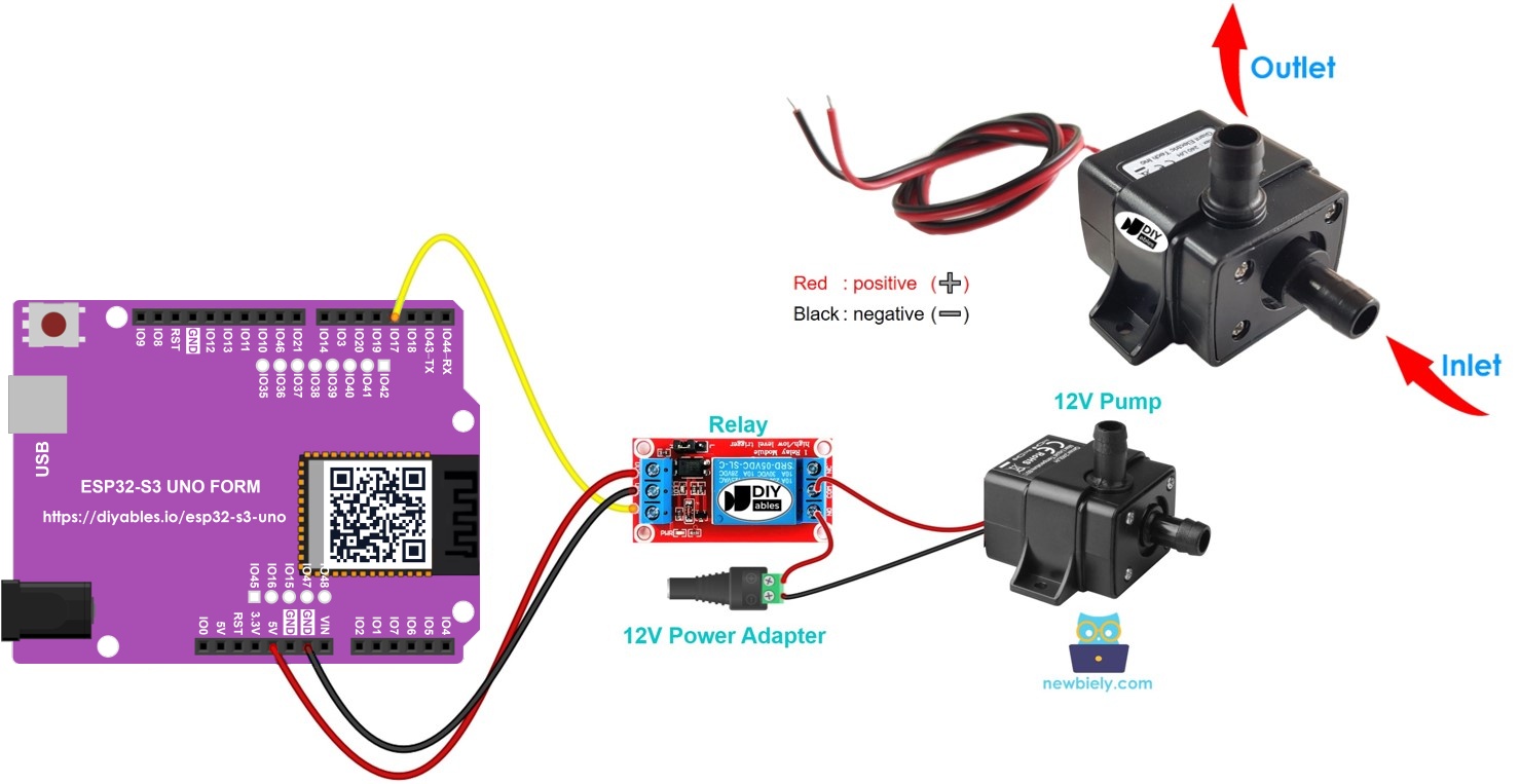
Hardware Preparation
| 1 | × | ESP32 S3 Uno-form Board | |
| 1 | × | USB Cable Type-A to Type-C (for USB-A PC) | |
| 1 | × | USB Cable Type-C to Type-C (for USB-C PC) | |
| 1 | × | Relay | |
| 1 | × | 12V Pump | |
| 1 | × | Vinyl Tube | |
| 1 | × | 12V Power Adapter | |
| 1 | × | DC Power Jack | |
| 1 | × | Jumper Wires |
Or you can buy the following kits:
| 1 | × | DIYables Sensor Kit (18 sensors/displays) |
Additionally, some of these links are for products from our own brand, DIYables .
Overview of 12V Pump
A small 12V pump moves water through a vinyl tube when it gets power. It is easy to use, but it needs much more power than a board pin can give. Knowing its pins helps you wire it the right way.
Pinout
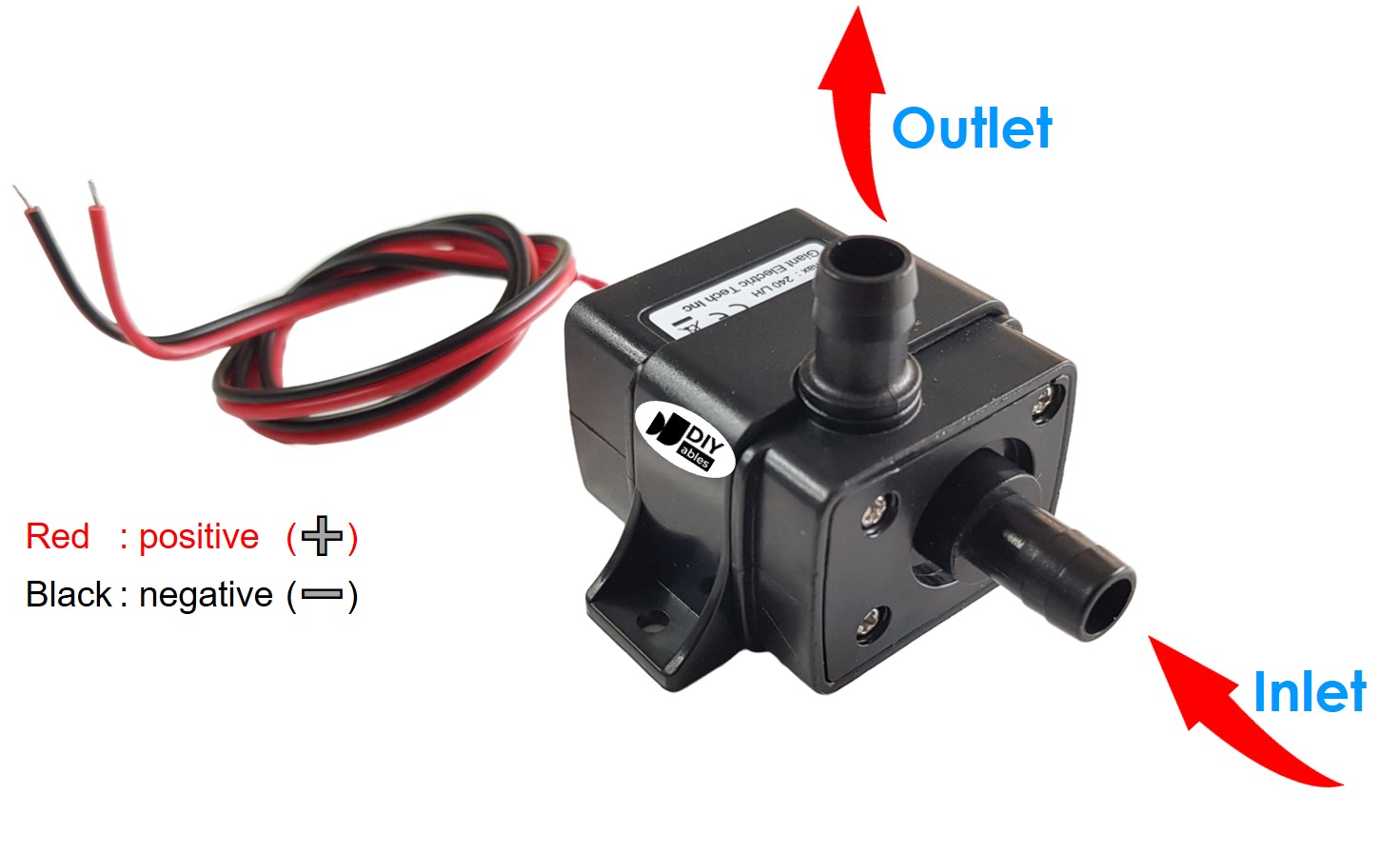
A 12V pump usually has just two pins. The black wire is the negative (-) pin, and it goes to GND of the DC power supply. The red wire is the positive (+) pin, and it goes to the 12V output of the power supply.
How to Control Pump
When you connect the pump to a 12V supply, it simply runs. To turn it on and off from code, you need a switch that the board can control.
Why use a relay
The ESP32 S3 Uno pins give only 3.3V and a small current, so they cannot run the pump. A relay sits between the board and the pump. The board sends a small signal to the relay, and the relay connects or cuts the pump's 12V power. If relays are new to you, read the ESP32 S3 Uno - Relay tutorial first. It explains the relay pinout, how it works, and how to program it.
ESP32 S3 Uno Pinout
The image below shows the pinout diagram of the ESP32 S3 Uno form board. Use it to find the Uno header pins (D3, 5V, GND…) and their GPIO numbers when you wire the pump circuit.

Wiring Diagram
The relay input goes to D3 (GPIO17). The pump and the 12V power adapter connect through the relay's screw terminals.
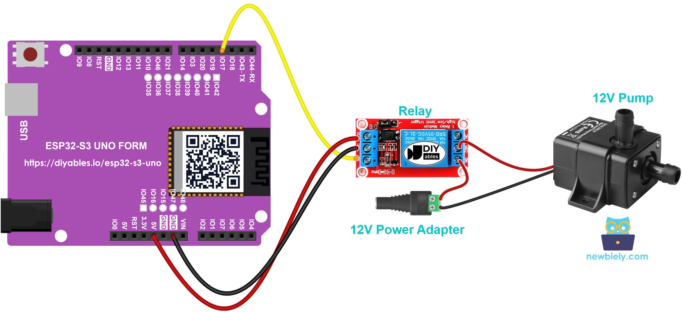
This image is created using Fritzing. Click to enlarge image
| Component Pin | ESP32 S3 Uno Pin |
|---|---|
| Relay VCC | 5V |
| Relay GND | GND |
| Relay IN | D3 (GPIO17) |
On the high-power side, connect the positive wire of the 12V power adapter (through the DC power jack) to the relay COM terminal. Connect the relay NO terminal to the pump's red (+) wire. Connect the pump's black (-) wire to the negative wire of the power adapter.
WARNING
Never connect the 12V supply to the ESP32 S3 Uno pins. The 12V power must only go to the relay terminals and the pump. The ESP32 S3 Uno pins work at 3.3V and are NOT 5V tolerant. The relay module may use 5V on its VCC pin, because its IN pin only receives a signal from the board.
ESP32 S3 Uno Code
This sketch turns the pump on for five seconds and then off for five seconds, again and again. It sets D3 (GPIO17) as an output and writes HIGH or LOW to it to switch the relay.
Detailed Instructions
Do these steps in order:
- New to the ESP32 S3 Uno? Follow ESP32 S3 Uno - Getting Started first.
- Wire it up as shown in the diagram.
- Connect the board to your computer with a USB Type-C cable.
- Open Arduino IDE, choose the ESP32S3 Dev Module board and the correct COM port.
- Copy the code above and paste it into Arduino IDE.
- Upload the code by clicking the Upload button.
- Put the pump in water and plug in the 12V power adapter.
- Watch the pump: it should pump water for five seconds, stop for five seconds, and repeat.
- Tip: do not run the pump dry for a long time. Most small pumps use the water to cool down, and running dry can damage them.
Code Explanation
The comments inside the code above explain each line. In short, pinMode() makes GPIO17 an output in setup(). Then loop() writes HIGH (pump on) and LOW (pump off), with a 5000 ms delay() between them.
Video Tutorial
Watch the video below to see this ESP32 S3 Uno project step by step.
Challenge Yourself
Try these ideas once the basic pump works:
- Build an automatic plant watering system with the ESP32 S3 Uno, a soil moisture sensor, and a pump.
- Make an automatic water refill system with the ESP32 S3 Uno, a water level sensor, and a pump.
FAQ
Can I connect a 12V pump directly to the ESP32 S3 Uno?
No. An ESP32 S3 Uno pin gives only 3.3V and a few milliamps. A 12V pump needs much more voltage and current. Use a relay or a MOSFET module with a separate 12V power supply.
Can I power the relay module from the 3.3V pin of the ESP32 S3 Uno?
Most relay modules have a 5V coil, so power their VCC from the 5V pin. The IN pin can still take the 3.3V signal from the ESP32 S3 Uno on most modules. If your relay does not click, use a 3V relay module or a module with a transistor driver.
Can I control the pump speed with the ESP32 S3 Uno?
Not with a relay. A relay can only switch the pump fully on or off. To change the flow, use a PWM signal with analogWrite() and a MOSFET driver.
Why does my pump run when the code says LOW?
Some relay modules are active LOW. They turn on when the IN pin is LOW. In that case, swap HIGH and LOW in the code, or move the pump wire from the NO terminal to the NC terminal.
What if my project needs more pins than the Uno headers give?
The ESP32 S3 Uno has two extra rows of holes with more GPIOs. GPIO15 and GPIO16 are I/O, PWM and analog. GPIO45 and GPIO35 to GPIO42 are I/O and PWM. GPIO47 and GPIO48 are output only, with PWM. Solder pin headers to use them and write the GPIO number in code. For more pumps or relays, GPIO35 to GPIO42 are a good choice. For a soil moisture or water level sensor, use GPIO15 or GPIO16. Be careful with two things. First, GPIO47 and GPIO48 may run at 1.8V instead of 3.3V on some modules (especially ones with "V" in the name, like R8V or R16V), so 3.3V devices can be damaged or act strangely. Second, GPIO0, GPIO3 (D6), GPIO45 and GPIO46 (D9) are boot strapping pins, and a wrong connection can stop the board from booting or uploading code. Use the other extra pins first.
Troubleshooting
| Problem | Possible Cause | Solution |
|---|---|---|
| No COM port in Arduino IDE | USB driver is missing or the cable is charge-only | Install the CP210x or CH340 driver, try a data USB cable, or hold BOOT while pressing RESET |
| Relay never clicks | Relay VCC or GND is not connected, or the relay needs 5V | Power the relay VCC from 5V and check the GND wire |
| Relay clicks but the pump does not run | The 12V adapter is not plugged in or the pump is on the NC terminal | Plug in the adapter and move the pump wire to the NO terminal |
| Pump works the opposite way to the code | The relay module is active LOW | Swap HIGH and LOW in the digitalWrite() lines |
| Pump runs but no water comes out | Air in the tube or the pump inlet is not under water | Put the pump fully in water and check that the tube is not bent |
| Board resets when the pump starts | Pump and board share a weak supply | Power the pump from its own 12V adapter and keep only the signal on the board |