
ESP32 S3 UNO - RGB LED
This ESP32 S3 Uno RGB LED tutorial shows you how to wire an RGB LED to the ESP32 S3 Uno form board and set its color with Arduino code. You can use a bare color LED with resistors or a ready-made RGB LED module, and the light changes between three colors you choose.
In this tutorial, you will:
- Learn how an RGB LED mixes red, green and blue light
- Wire an RGB LED and an RGB LED module to the ESP32 S3 Uno
- Turn a hex color code into R, G and B values
- Write code that sets the LED color with analogWrite()
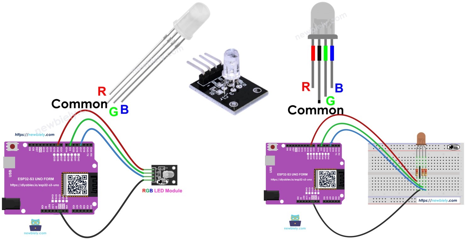
Hardware Preparation
| 1 | × | ESP32 S3 Uno-form Board | |
| 1 | × | USB Cable Type-A to Type-C (for USB-A PC) | |
| 1 | × | USB Cable Type-C to Type-C (for USB-C PC) | |
| 1 | × | RGB LED Module | |
| 1 | × | Alternatively, RGB LED | |
| 1 | × | Breadboard | |
| 1 | × | Jumper Wires |
Or you can buy the following kits:
| 1 | × | DIYables Sensor Kit (18 sensors/displays) |
Additionally, some of these links are for products from our own brand, DIYables .
Overview of RGB LED
An RGB LED is really three small LEDs in one package: a red one, a green one and a blue one. When you change how bright each one is, their light blends together. This way, one LED can show almost any color you want.
Pinout
Before you wire anything, you need to know what each leg does. A common cathode RGB LED has four pins.
Common pin (Cathode -)
This is the longest leg. Connect it to GND (0V).
R, G and B pins
The R pin drives the red LED, the G pin drives the green LED, and the B pin drives the blue LED. Each one needs its own control signal.
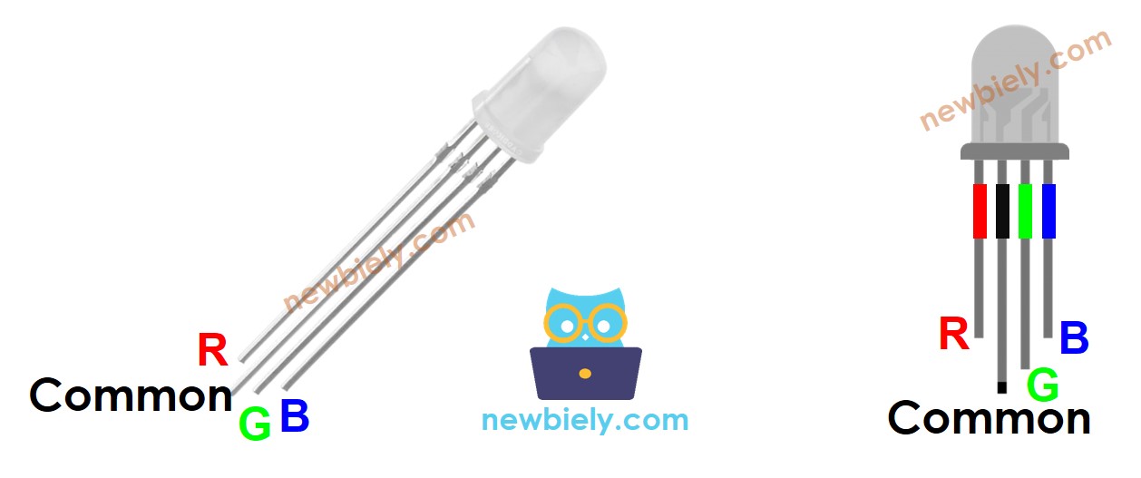
A bare RGB LED needs a current-limiting resistor on each color pin, so the breadboard gets a bit busy. If you want a cleaner setup, use an RGB LED module. It already has the resistors on board.
The RGB LED module also has four pins, and they work the same way. The common (Cathode -) pin goes to GND, and the R, G and B pins control the red, green and blue light.
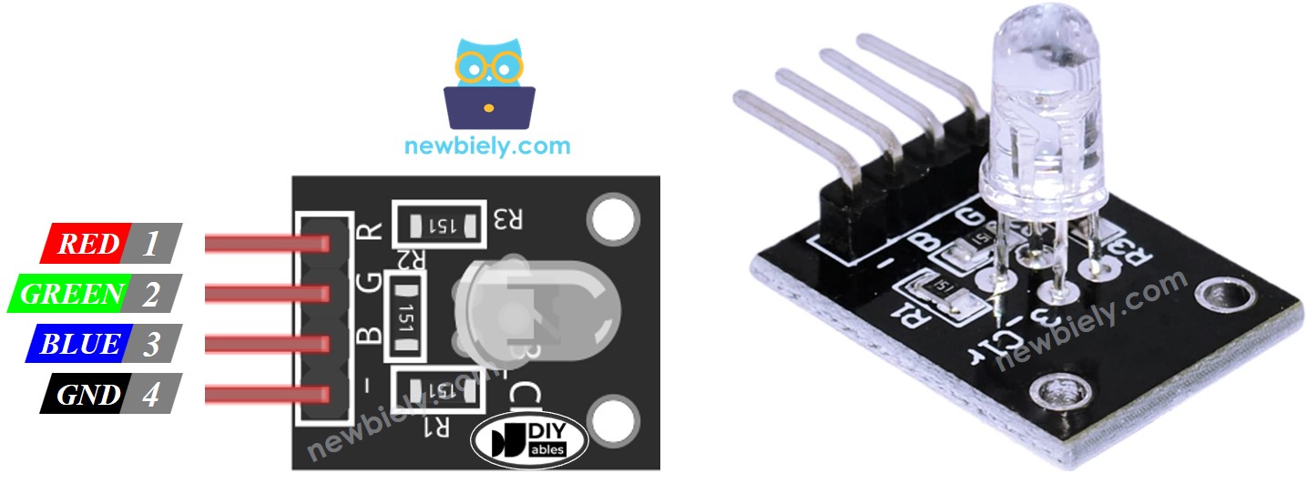
※ NOTE THAT:
The LED in this tutorial is a common cathode type, so its shared pin is the negative side. Some RGB LEDs are common anode instead, where the shared pin is the positive side. Check your LED before wiring.
How it works
Every screen color is described by three numbers: Red (R), Green (G) and Blue (B). Each number goes from 0 to 255. That gives 256 x 256 x 256, or about 16.7 million, possible colors.
The ESP32 S3 Uno sends a PWM signal to each color pin. The duty cycle, set from 0 to 255, decides how bright that color is. So when you write the R, G and B values of a color to the three pins, the RGB LED shows that color.
ESP32 S3 Uno Pinout
The image below shows the pinout diagram of the ESP32 S3 Uno form board. Use it to find the Uno header pins (D3, D6, D9…) and their GPIO numbers while you wire the RGB LED.

Wiring Diagram
You can build this project with a bare RGB LED or with an RGB LED module. Both use the same three PWM pins on the ESP32 S3 Uno.
Wiring an RGB LED
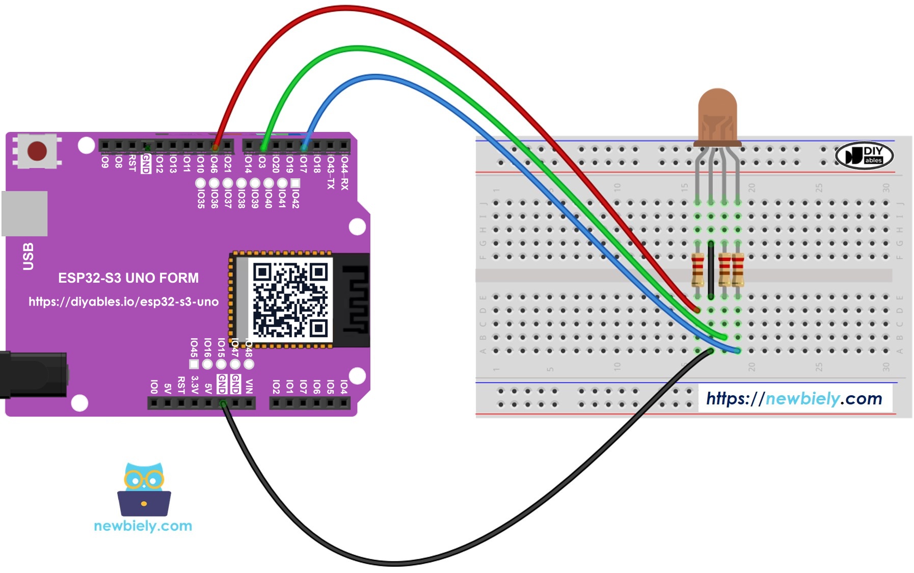
This image is created using Fritzing. Click to enlarge image
| RGB LED Pin | ESP32 S3 Uno Pin |
|---|---|
| R (through a resistor) | D9 (GPIO46) |
| G (through a resistor) | D6 (GPIO3) |
| B (through a resistor) | D3 (GPIO17) |
| Common (Cathode -) | GND |
Put one resistor on each of the R, G and B pins, as in the diagram. Do not use a single resistor on the common pin. The three LEDs inside the package are not exactly the same, so they would not share the current evenly. The colors would look uneven, and one LED could even get damaged.
Wiring an RGB LED module
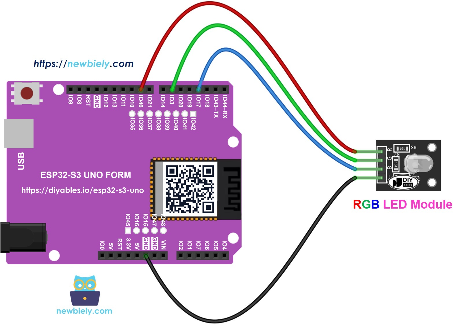
This image is created using Fritzing. Click to enlarge image
| RGB LED Module Pin | ESP32 S3 Uno Pin |
|---|---|
| R | D9 (GPIO46) |
| G | D6 (GPIO3) |
| B | D3 (GPIO17) |
| Common (Cathode -) | GND |
WARNING
D9 (GPIO46) and D6 (GPIO3) are boot strapping pins on the ESP32 S3 Uno. The chip reads them at startup to choose its boot mode. An LED with a resistor to GND is usually fine, but if the board does not start or will not upload code, unplug the R and G wires, upload, and then plug them back in.
How To Control RGB LED
Picking a color by its code is the easiest way to get exactly the shade you want. Here is how to show the color #00979D on the RGB LED, step by step.
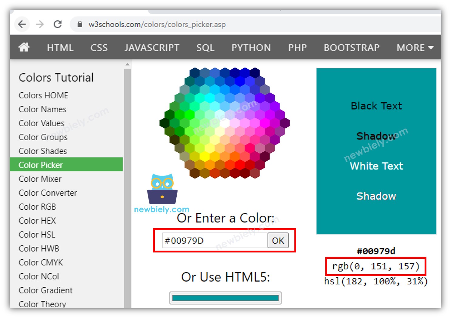
- Pick a color and note its code. You can choose one with this color picker, or take a color from a photo with the Colors From Image tool.
- Convert the code to RGB values with this tool. For #00979D you get R = 0, G = 151, B = 157.
- Name the pins that go to the R, G and B legs. On the ESP32 S3 Uno you write the GPIO number:
- Set the pins as outputs in setup():
- Write the PWM values to show the color (#00979D; R = 0, G = 151, B = 157):
ESP32 S3 Uno - RGB LED Example Code
This sketch cycles the RGB LED through three colors and holds each one for one second. The colors are:
- #00C9CC (R = 0, G = 201, B = 204)
- #F7788A (R = 247, G = 120, B = 138)
- #34A853 (R = 52, G = 168, B = 83)
Detailed Instructions
- New to the ESP32 S3 Uno? Follow ESP32 S3 Uno - Getting Started first.
- Wire it up as shown in the diagram.
- Connect the board to your computer with a USB Type-C cable.
- Open Arduino IDE, choose the ESP32S3 Dev Module board and the correct COM port.
- Copy the code above and paste it into Arduino IDE.
- Upload the code by clicking the Upload button.
- Watch the LED change from teal to pink to green, and then start again.
- Tip: if a color looks wrong, check that the R, G and B wires go to D9, D6 and D3 in that order.
Shorter code with a function
When you work with many colors, writing three analogWrite() lines each time gets long. A small setColor() function keeps the loop short and easy to read. The result on the LED is the same as before.
Addtional Knowledge
A few extra facts help when you move on to other RGB parts.
Common anode RGB LED
If your RGB LED is common anode, connect the common pin to the 3.3V pin of the ESP32 S3 Uno. Then invert each value in analogWrite(): write 255 - R, 255 - G and 255 - B. A low signal now turns a color on, and a high signal turns it off.
RGB LED strips
Many RGB LEDs chained together make an RGB LED strip. Strips come in two types: addressable and non-addressable. Each type needs a different approach, and each has its own tutorial.
FAQ
Why does my RGB LED show the wrong color?
The R, G and B wires are probably swapped, or your LED is a common anode type. Check that red goes to D9 (GPIO46), green to D6 (GPIO3) and blue to D3 (GPIO17). If the colors look inverted, use 255 minus each value.
Does analogWrite() work on the ESP32 S3 Uno?
Yes. The esp32 by Espressif Systems core supports analogWrite() with values from 0 to 255, just like on other Arduino boards. It uses the LEDC PWM hardware inside the chip. Make sure your esp32 core is up to date.
Is the RGB LED less bright on the ESP32 S3 Uno than on a 5V board?
It can be a little dimmer. The ESP32 S3 Uno pins give 3.3V, not 5V, so less current flows through the same resistor. If you build the circuit yourself, a slightly smaller resistor, such as 150 to 220 ohms, gives more light while staying safe.
Why do I write 46, 3 and 17 in the code instead of 9, 6 and 3?
On the ESP32 S3 Uno, the header labels D9, D6 and D3 are only positions on the board. The code needs the real GPIO numbers behind them. D9 is GPIO46, D6 is GPIO3 and D3 is GPIO17.
Can I use an RGB LED shield made for the UNO R4?
Often yes, if the shield only uses the Uno headers and works at 3.3V. Keep in mind that the ESP32 S3 Uno pins are not 5V tolerant. Check the shield's pins against the ESP32 S3 Uno pinout before you plug it in.
What if my project needs more RGB LEDs than the Uno headers give?
The ESP32 S3 Uno has two extra rows of holes with more GPIOs. GPIO15 and GPIO16 support I/O, PWM and analog. GPIO45 and GPIO35 to GPIO42 support I/O and PWM. GPIO47 and GPIO48 are output only, with PWM. Solder pin headers to use them and write the GPIO number in your code. For a second RGB LED, GPIO35 to GPIO42 are a good choice, because the LED only needs PWM outputs. Keep two warnings in mind. First, GPIO47 and GPIO48 may run at 1.8V instead of 3.3V on some modules (especially ones with "V" in the name, like R8V or R16V), so 3.3V devices can be damaged or act strangely. Second, GPIO0, GPIO3 (D6), GPIO45 and GPIO46 (D9) are boot strapping pins, and a wrong connection can stop the board from booting or uploading code. Use the other extra pins first.
Troubleshooting
| Problem | Possible Cause | Solution |
|---|---|---|
| No COM port shows up in Arduino IDE | USB driver missing or board not in upload mode | Install the CP210x or CH340 driver, use a data USB cable, or hold BOOT while pressing RESET |
| Upload fails or the board does not start | Red or green wire on a boot strapping pin (D9 or D6) | Unplug the R and G wires, upload the code, then plug them back in |
| LED does not light at all | Common pin not on GND or loose breadboard wire | Check the GND wire and press all wires in firmly |
| Only one or two colors work | A color wire is loose or on the wrong pin | Check that R goes to D9, G to D6 and B to D3 |
| Colors are inverted | The LED is a common anode type | Connect the common pin to 3.3V and write 255 minus each value |
| LED is very dim | Resistor value too high for 3.3V | Use a smaller resistor, such as 150 to 220 ohms |
| One color is much brighter than the others | A single resistor is used on the common pin | Use one resistor on each color pin instead |
| analogWrite() causes a compile error | Old esp32 core version | Update the esp32 by Espressif Systems core in Boards Manager |