
ESP32 S3 UNO - Water Sensor
This ESP32 S3 Uno water sensor tutorial shows you how to wire a water level sensor to the ESP32 S3 Uno form board and read it with Arduino code. With this simple water detector you can catch a water leak, sense rainfall, warn about a tank overflow, or measure how high the water is.
In this tutorial, you will:
- Wire a water level sensor to the ESP32 S3 Uno
- Read the sensor value with analogRead() in Arduino IDE
- Detect water leakage, rain or tank overflow with a threshold
- Measure the water level in several steps
- Calibrate the water sensor for your own water
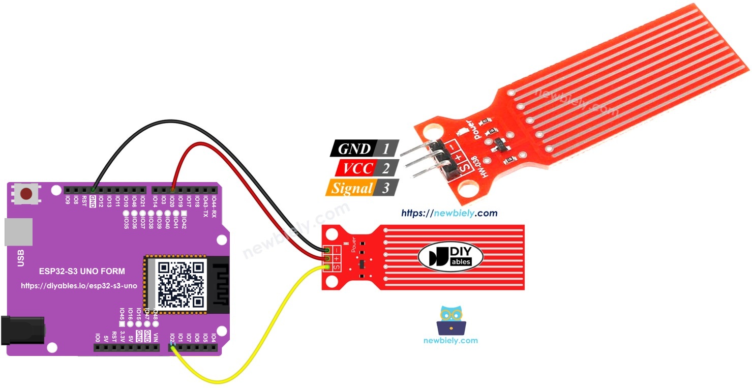
Hardware Preparation
| 1 | × | ESP32 S3 Uno-form Board | |
| 1 | × | USB Cable Type-A to Type-C (for USB-A PC) | |
| 1 | × | USB Cable Type-C to Type-C (for USB-C PC) | |
| 1 | × | Water level sensor | |
| 1 | × | Jumper Wires |
Or you can buy the following kits:
| 1 | × | DIYables Sensor Kit (18 sensors/displays) |
Additionally, some of these links are for products from our own brand, DIYables .
Overview of Water Level Sensor
A water level sensor is a cheap and simple way to find out if water is present, and roughly how deep it is. It has no moving parts. It only uses copper traces and the fact that normal water conducts electricity.
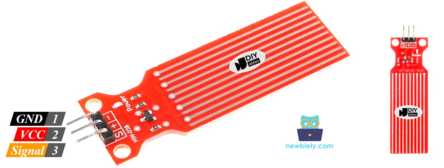
Water Level Sensor Pinout
The sensor has only three pins, so the wiring is quick.
| Pin | What It Does |
|---|---|
| S (Signal) | Analog output. Connect it to an analog input pin of the ESP32 S3 Uno |
| + (VCC) | Power input, 3.3V to 5V. With the ESP32 S3 Uno, power it with 3.3V (from a GPIO pin, see below) |
| * (GND) | Ground (0V) |
※ NOTE THAT:
The voltage on the signal pin depends on the voltage you give to the VCC pin. If you change the supply voltage, the readings change too.
How Water Level Sensor Works
The idea is simple: the deeper the sensor goes into water, the higher the voltage on the signal pin. The details below explain why.
Copper traces
Look at the sensor and you will see ten copper traces. Five are power traces and five are sense traces. They sit side by side, and each sense trace lies between two power traces. In dry air the traces do not touch. When the sensor goes into water, the water connects them.
A variable resistor made of water
Together, the traces act like a variable resistor, a bit like a potentiometer. Its resistance depends on how much of the sensor is under water. When more of the sensor is in water, current flows more easily and the resistance goes down. When less of the sensor is in water, the resistance goes up.
From resistance to voltage
The sensor turns this resistance into an output voltage. So when you measure the voltage on the signal pin, you know how far the water has climbed up the sensor.
ESP32 S3 Uno Pinout
The image below shows the pinout of the ESP32 S3 Uno form board. Use it to find the Uno header pins (D5, A0…) and their GPIO numbers when you wire the sensor.

Wiring Diagram
A water sensor that has power all the time in a wet place corrodes fast and does not last long. To avoid this, the diagram powers the sensor from a digital pin, not from a power pin. The code sets this pin HIGH just before it reads the sensor, and sets it LOW right after. A GPIO pin gives 3.3V, which is the right voltage for the ESP32 S3 Uno.
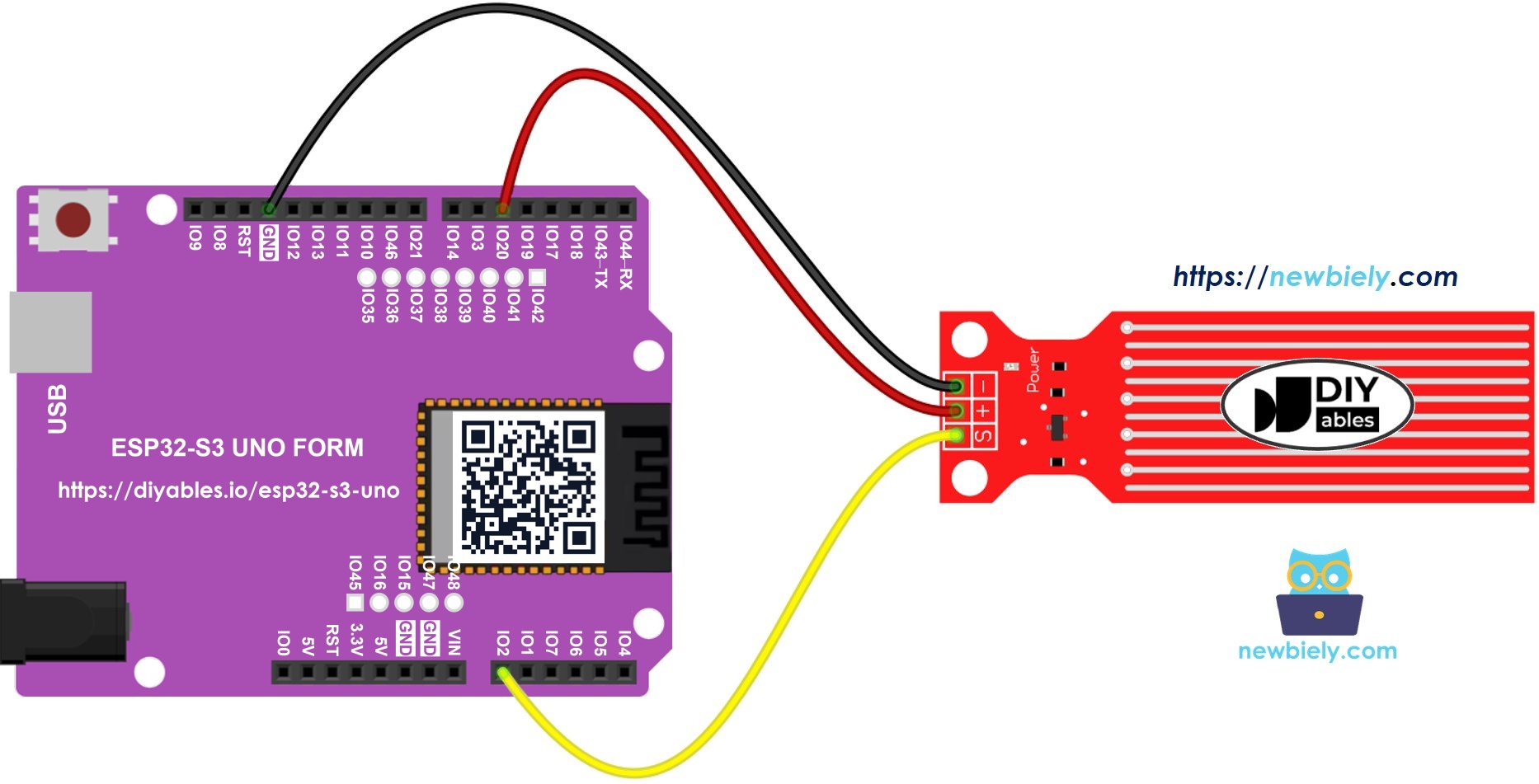
This image is created using Fritzing. Click to enlarge image
| Water Sensor Pin | ESP32 S3 Uno Pin |
|---|---|
| + (VCC) | D5 (GPIO20) |
| * (GND) | GND |
| S (Signal) | A0 (GPIO2) |
WARNING
ESP32 S3 Uno pins are NOT 5V tolerant. Do not power the sensor from the 5V pin. With 5V on VCC, the signal pin can go above 3.3V and damage the analog input. Keep the sensor powered from D5 (GPIO20) or from the 3.3V pin.
ESP32 S3 Uno Code - Reading Value from Water Sensor
This first sketch powers the sensor for a short moment, reads the signal pin, and turns the power off again. It prints the raw value to the Serial Monitor once per second. On the ESP32 S3 Uno the value goes from 0 to 4095, because the ADC is 12-bit.
The sketch calls analogSetAttenuation(ADC_11db) in setup(). By default, the ESP32 S3 Uno ADC can only measure a small voltage. The 11 dB setting lets the analog pin read the full range, from 0V up to about 3.3V. Without it, the reading hits 4095 too early and the water values look wrong.
Detailed Instructions
Do these steps in order:
- New to the ESP32 S3 Uno? Follow ESP32 S3 Uno - Getting Started first.
- Wire it up as shown in the diagram.
- Connect the board to your computer with a USB Type-C cable.
- Open Arduino IDE, choose the ESP32S3 Dev Module board and the correct COM port.
- Copy the code above and paste it into Arduino IDE.
- Upload the code by clicking the Upload button.
- Lower the sensor slowly into a glass of water.
- Open the Serial Monitor at 9600 baud and watch the values. The value is 0 while the sensor touches nothing.
- Tip: Write down the values you see at different depths. You will need them for the leak threshold and the level steps below.
※ NOTE THAT:
Never put the whole sensor under water. Only the bare copper traces on the board may touch the water. Mount the sensor with care so the electronics and the pins stay dry.
How To Detect Water Leakage
A leak, rain or a tank overflow all mean the same thing for the sensor: water has reached it. So the code only needs to compare the reading with a threshold. You find the right threshold in the calibration section of this tutorial.
ESP32 S3 Uno Code - Detecting Water Leakage
The threshold of 1200 is only a starting point for the 12-bit ADC. Replace it with the value you measure in your own water.
How To Measure The Water Level
Sometimes "wet or dry" is not enough, and you want to know how full a tank is. The sketch below splits the full height of the sensor into 4 steps and prints the current step. The highest level it can measure is the height of the sensor itself.
※ NOTE THAT:
- You find SENSOR_MIN and SENSOR_MAX during calibration.
- The map() method is simple and not very precise, but it is good enough for many projects. For better results, measure a separate threshold for each level, as the calibration section explains.
Water Level Sensor Calibration
Two things change the sensor reading: the water level and how well the water conducts electricity. Pure water hardly conducts at all. Tap water, rain water and dirty water hold minerals, so they conduct much better. The better the water conducts, the more sensitive the sensor gets. The supply voltage on the VCC pin also changes the values.
Because of this, you get the best results when you calibrate the sensor with the same water you plan to watch. Do a short test before you pick any threshold.
How to do the test
- Upload the first sketch that prints the raw sensor value.
- Put the sensor into the water up to the level you care about.
- Read the value in the Serial Monitor.
- Use this value as the threshold that starts your action.
You may need a few tries to get a stable number.
What the test tells you
With the same test you can find the lowest value (sensor out of the water), the highest value (all traces under water), the threshold for leak detection, and the threshold for each step of your level scale.
Video Tutorial
Watch the video below to see this ESP32 S3 Uno project step by step.
The demo in the video uses the code below. It reads the water sensor with a simple filter (EMA), turns the level into a 0 to 4 scale, shows it on an LCD 20x4 I2C, lights a green, yellow or red LED, and beeps a buzzer at the top level. The calibrated range is set for the 12-bit ADC (0 to 4095).
| Demo Part | ESP32 S3 Uno Pin |
|---|---|
| Water sensor + (VCC) | D5 (GPIO20) |
| Water sensor S (Signal) | A0 (GPIO2) |
| Green LED | D6 (GPIO3) |
| Yellow LED | D7 (GPIO14) |
| Red LED | D8 (GPIO21) |
| Buzzer | D9 (GPIO46) |
| LCD SDA | SDA (GPIO8) |
| LCD SCL | SCL (GPIO9) |
WARNING
The green LED is on D6 (GPIO3) and the buzzer is on D9 (GPIO46). Both are boot strapping pins on the ESP32 S3 Uno. If a part pulls one of these pins HIGH while the board starts, the board may not boot or may fail to upload code. Connect the LED and the buzzer to GND through their resistor or module (not to 3.3V). If you have boot or upload problems, unplug these wires and try again. The LCD also runs on 5V, and many LCD I2C backpacks pull SDA and SCL up to 5V, so use a 5V to 3.3V level converter on these two lines.
Function References
FAQ
Can I power the water sensor from 5V on the ESP32 S3 Uno?
It is not a good idea. With 5V on VCC, the signal pin can go above 3.3V, and ESP32 S3 Uno pins are not 5V tolerant. Power the sensor from a GPIO pin (3.3V) or the 3.3V pin, so the signal stays in a safe range.
Why do I get values up to 4095 instead of 1023?
The ESP32 S3 Uno has a 12-bit ADC, so analogRead() returns 0 to 4095. The UNO R4 uses 10-bit by default and returns 0 to 1023. If you copy thresholds from an UNO R4 project, multiply them by about 4, then check them again with your own water.
Why does the code call analogSetAttenuation(ADC_11db)?
It sets the ESP32 S3 Uno ADC input range to about 0V to 3.3V, so the full water sensor signal maps to 0 to 4095. Without it the range is smaller, and the readings saturate early. The UNO R4 does not need this line, because it is ESP32-only. Keep the signal voltage at 3.3V or less.
Why is the sensor powered from a digital pin?
A water sensor that has power all the time slowly corrodes in a wet place. Powering it from D5 (GPIO20) only during a reading keeps the copper traces in good shape much longer. The sensor draws very little current, so a GPIO pin can power it.
Can the water sensor measure the exact water depth?
Not very well. The reading depends on the water's minerals, the temperature and the supply voltage, and it is not linear. It is great for leak, rain and overflow alarms, and for a rough level in a few steps. For exact depth, use an ultrasonic or pressure sensor.
What if my project needs more pins than the Uno headers give?
The ESP32 S3 Uno has two extra rows of holes with more GPIOs: GPIO15 and GPIO16 (I/O, PWM, analog), GPIO45 and GPIO35 to GPIO42 (I/O, PWM), and GPIO47/GPIO48 (output only, PWM). Solder pin headers to use them and write the GPIO number in your code. For a second water sensor, use GPIO15 or GPIO16 for the signal pin and GPIO35 to GPIO42 for its power pin. Do not use GPIO47/GPIO48 as sensor inputs. Two warnings: (1) GPIO47/GPIO48 may run at 1.8V instead of 3.3V on some modules (especially ones with "V" in the name, like R8V or R16V), so 3.3V devices can be damaged or act strangely. (2) GPIO0, GPIO3 (D6), GPIO45 and GPIO46 (D9) are boot strapping pins, and a wrong connection can stop the board from booting or uploading code. Use the other extra pins first.
Troubleshooting
| Problem | Possible Cause | Solution |
|---|---|---|
| No COM port shows up in Arduino IDE | USB driver missing or board not in upload mode | Install the CP210x or CH340 driver, use a data USB cable, or hold BOOT while you press RESET |
| Value is always 0 even in water | No power on the sensor or loose wire | Check that + goes to D5 (GPIO20), S goes to A0 (GPIO2) and GND is connected |
| Value stays at 4095 | Attenuation not set, or sensor powered from 5V | Keep analogSetAttenuation(ADC_11db) in setup() and power the sensor from D5 or 3.3V |
| Values are much lower than expected | Very pure or distilled water conducts poorly | Calibrate with the real water you will watch, and lower the threshold |
| Leak message never appears | Threshold too high for your water | Run the first sketch, read the wet value and set THRESHOLD below it |
| Readings drift over weeks | Copper traces corrode | Power the sensor only when reading, and replace the sensor when the traces look dark |
| Board does not boot or upload with the demo wired | LED on D6 (GPIO3) or buzzer on D9 (GPIO46) pulls a boot strapping pin | Wire them to GND, or unplug them while uploading |
| Serial Monitor shows strange characters | Baud rate does not match the code | Use 9600 baud for the first three sketches and 115200 baud for the demo |