
ESP32 S3 UNO - Measure Voltage
This ESP32 S3 Uno measure voltage tutorial shows you how to read a DC voltage from 0V to about 16.5V with a voltage sensor module. You will wire the volt sensor to the ESP32 S3 Uno form board, upload the Arduino code, and see the measured voltage in the Serial Monitor.
In this tutorial, you will:
- Learn how a voltage sensor module works as a voltage divider
- Wire the voltage sensor to the A0 pin of the ESP32 S3 Uno
- Convert the 12-bit analogRead() value into the real input voltage
- Find out why the maximum input is 16.5V instead of 25V on a 3.3V board
- Get more accurate readings with analogReadMilliVolts()
Hardware Preparation
| 1 | × | ESP32 S3 Uno-form Board | |
| 1 | × | USB Cable Type-A to Type-C (for USB-A PC) | |
| 1 | × | USB Cable Type-C to Type-C (for USB-C PC) | |
| 1 | × | Voltage Sensor | |
| 1 | × | Jumper Wires |
Or you can buy the following kits:
| 1 | × | DIYables Sensor Kit (18 sensors/displays) |
Additionally, some of these links are for products from our own brand, DIYables .
Overview of Voltage Sensor
The analog pins of the ESP32 S3 Uno can only read up to about 3.3V. A voltage sensor module lets you measure higher voltages, such as a 12V battery, without hurting the board.
The module is a simple voltage divider made with two precise resistors: R1 = 30 kΩ and R2 = 7.5 kΩ. It divides the input voltage by 5. So when 10V goes into the module, only 2V comes out on the signal pin.
The module is sold as a "0 to 25V" sensor. That number is only true for boards with a 5V ADC, because 25V divided by 5 is 5V. The ESP32 S3 Uno ADC works with 3.3V, so the highest voltage you can safely measure is 3.3V x 5 = 16.5V DC.
| Board ADC Range | Module Output Max | Max Input Voltage |
|---|---|---|
| 5V (old 5V boards) | 5V | 25V DC |
| 3.3V (ESP32 S3 Uno) | 3.3V | 16.5V DC |
WARNING
The module output (S pin) must never go above 3.3V. The ESP32 S3 Uno pins are NOT 5V tolerant. Do not connect more than 16.5V to the input side of the module, even though the module label says 25V. Higher voltages can damage GPIO2 or the whole board.
Pinout
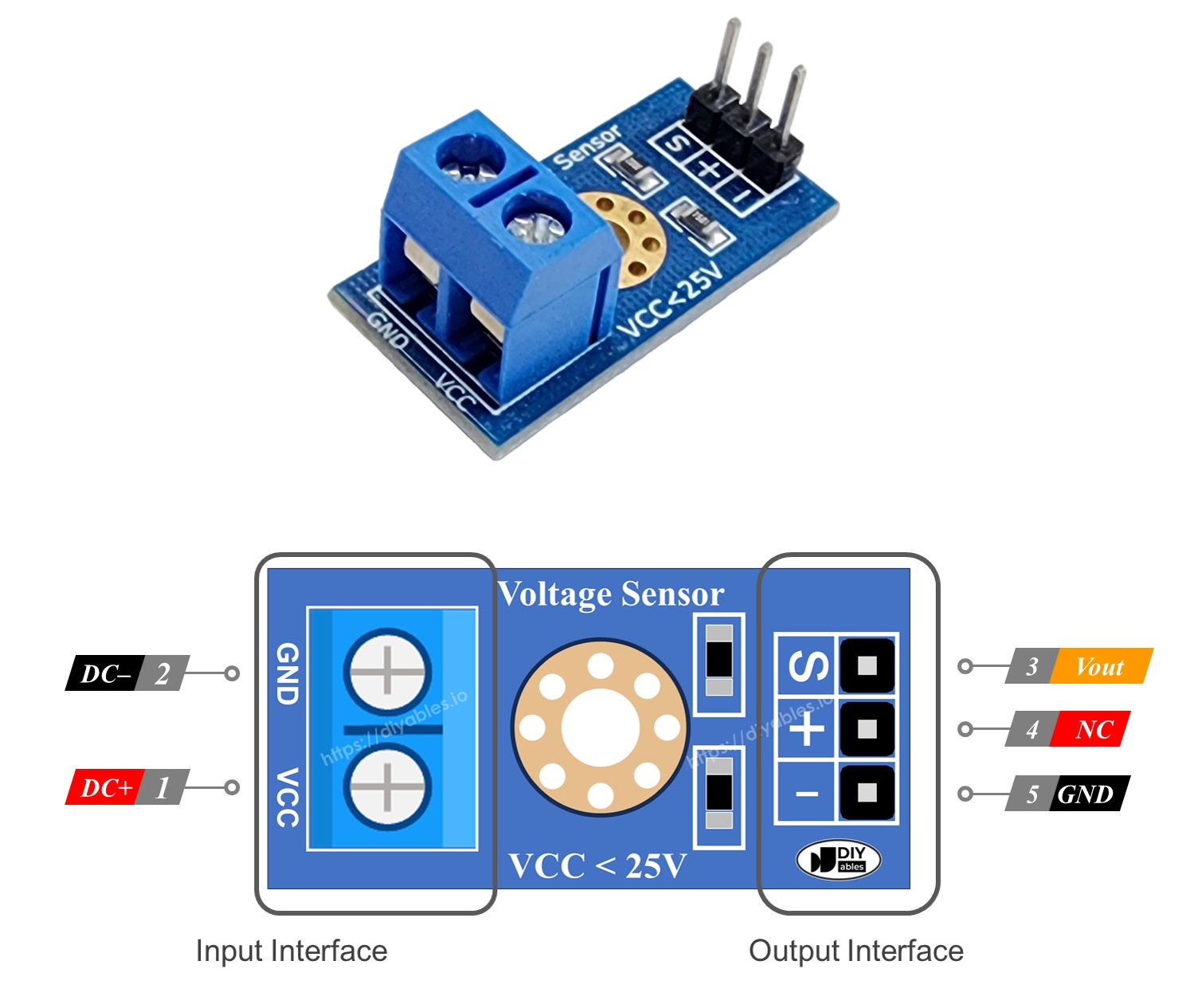
The module has two groups of pins. One group goes to the circuit you want to measure, and the other group goes to the ESP32 S3 Uno.
Input side (the voltage you measure)
- VCC pin: the positive input. Connect it to the higher voltage point.
- GND pin: the negative input. Connect it to the lower voltage point.
Output side (to the ESP32 S3 Uno)
- S pin (Vout): the signal pin. Connect it to an analog pin on the ESP32 S3 Uno.
- + pin (NC): not connected inside the circuit. Leave it unconnected.
- - pin: the ground pin. Connect it to GND on the ESP32 S3 Uno.
ESP32 S3 Uno Pinout
The image below shows the pinout of the ESP32 S3 Uno form board. Use it to find the A0 header and its GPIO number before you wire the sensor.

Wiring Diagram
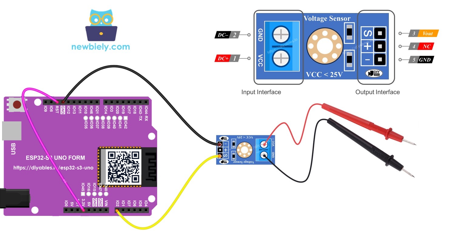
Only two wires go from the module to the board: the signal wire to A0 and the ground wire to GND. The voltage you want to measure goes to the VCC and GND screw terminals of the module.
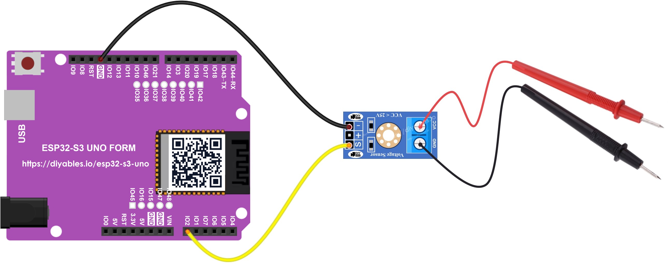
This image is created using Fritzing. Click to enlarge image
| Voltage Sensor Pin | ESP32 S3 Uno Pin |
|---|---|
| S (Vout) | A0 (GPIO2) |
| + (NC) | not connected |
| * | GND |
| VCC (input) | the positive point you want to measure |
| GND (input) | the negative point you want to measure |
WARNING
The ground of the circuit you measure is joined to the ESP32 S3 Uno GND through the module. Only measure DC voltages that share this common ground, and keep them at 16.5V or lower. Never use this module for mains (AC) voltage.
ESP32 S3 Uno Code
The sketch reads the module's signal on A0 (GPIO2) every half second. It turns the 12-bit ADC value into the voltage on the pin, then multiplies it by the divider ratio (R1 + R2) / R2 = 5 to get the real input voltage. The result is printed with two decimal places.
The ESP32 S3 Uno ADC returns values from 0 to 4095, so the code uses 3.3 for the reference and 4096.0 for the resolution, not 5.0 and 1024.0. The line analogSetAttenuation(ADC_11db); in setup() also matters. By default, the ESP32 S3 Uno ADC can only measure a small voltage. With 11 dB attenuation, the analog pin reads the full range from 0V up to about 3.3V. Without it, the reading hits 4095 too early and the measured voltage looks wrong.
Detailed Instructions
Follow these steps in order:
- New to the ESP32 S3 Uno? Follow ESP32 S3 Uno - Getting Started first.
- Wire it up as shown in the diagram.
- Connect the board to your computer with a USB Type-C cable.
- Open Arduino IDE, choose the ESP32S3 Dev Module board and the correct COM port.
- Copy the code above and paste it into Arduino IDE.
- Upload the code by clicking the Upload button.
- Open the Serial Monitor and set the baud rate to 9600.
- Test the sensor by connecting the module's VCC input to the 5V pin of the ESP32 S3 Uno, then to the 3.3V pin. The module's GND input goes to GND.
- Check the result on the Serial Monitor.
- Tip: The 5V pin gives 5V / 5 = 1V on the S pin, so this test is always safe for the ESP32 S3 Uno. Use a multimeter on the same point to compare the numbers.
Your reading may be a little different from a multimeter. This is not a fault of the voltage sensor. The ESP32 S3 Uno ADC is not perfectly linear, each chip is slightly different, and readings close to 0V or above about 3.1V on the pin (about 15.5V on the input) are less accurate. Here is how to improve it:
- Check the real voltage with a multimeter, and compare it with the Serial Monitor value. If the error is always about the same percent, multiply the result by a small correction factor in the code.
- Use the calibrated reading in the next section. It uses the factory calibration stored inside the chip.
- Read the pin several times and use the average, because the ESP32 S3 Uno ADC is a bit noisy.
Measuring Voltage More Accurately
On some Arduino boards you wire the AREF pin to an external 3.3V reference to get steadier readings. The ESP32 S3 Uno has no AREF pin, so you do not need any extra wire. Keep the same wiring as above.
Instead, the esp32 Arduino core (by Espressif Systems) gives you analogReadMilliVolts(). This function reads the pin and uses the chip's factory calibration to return the pin voltage in millivolts. The code below uses it, then applies the same divide-by-5 math. The maximum input is still 16.5V.
Upload it the same way as the first sketch. You should see values that are closer to your multimeter, especially in the middle of the range.
Video Tutorial
Watch the video below to see this ESP32 S3 Uno project step by step.
Function References
FAQ
What is the maximum voltage I can measure with the ESP32 S3 Uno and this voltage sensor?
About 16.5V DC. The module divides the input by 5, and the ESP32 S3 Uno analog pin can only take up to 3.3V, so 3.3V x 5 = 16.5V. The "25V" on the module is for 5V boards only. For accurate results, stay below about 15V.
Can I measure 24V with the ESP32 S3 Uno?
Not with this module alone. 24V divided by 5 is 4.8V, which is above 3.3V and can damage the pin, because the ESP32 S3 Uno pins are not 5V tolerant. Use a divider with a bigger ratio, for example 100 kΩ and 10 kΩ (divide by 11), and change R1 and R2 in the code.
Why does the code use 4096 and 3.3 instead of 1024 and 5.0?
The ESP32 S3 Uno has a 12-bit ADC that returns 0 to 4095, and its analog input range is about 0V to 3.3V. Code written for 10-bit, 5V boards uses 1024 and 5.0. If you keep those numbers on the ESP32 S3 Uno, the measured voltage will be wrong.
Why does the code call analogSetAttenuation(ADC_11db)?
It sets the ESP32 S3 Uno ADC input range to about 0V to 3.3V, so the full module output maps to 0 to 4095. Without it, the range is smaller and the reading saturates early, so the voltage shows too high or stops rising. The UNO R4 does not need this line, it is only for ESP32 boards. Always keep the module output at 3.3V or less.
Can I measure AC or mains voltage with this module?
No. The module is made for DC voltage only, and its ground is joined to the board ground. Never connect it to mains. For AC, use an isolated AC voltage sensor module.
What if my project needs more pins than the Uno headers give?
The ESP32 S3 Uno has two extra rows of holes with more GPIOs. GPIO15 and GPIO16 support I/O, PWM and analog. GPIO45 and GPIO35 to GPIO42 support I/O and PWM. GPIO47 and GPIO48 are output only, with PWM. Solder pin headers to use them and write the GPIO number in your code. To measure a second voltage, use GPIO15 or GPIO16, because they are the only extra pins that can read analog values. Keep two warnings in mind. First, GPIO47 and GPIO48 may run at 1.8V instead of 3.3V on some modules (especially ones with "V" in the name, like R8V or R16V), so 3.3V devices can be damaged or act strangely. Second, GPIO0, GPIO3 (D6), GPIO45 and GPIO46 (D9) are boot strapping pins, and a wrong connection can stop the board from booting or uploading code. Use the other extra pins first.
Troubleshooting
| Problem | Possible Cause | Solution |
|---|---|---|
| No COM port shows up in Arduino IDE | USB driver missing or board not in upload mode | Install the CP210x or CH340 driver, use a data USB cable, or hold BOOT while pressing RESET |
| Nothing prints on the Serial Monitor | Wrong baud rate | Set the Serial Monitor to 9600 baud |
| Value is always 0.00 | S wire not on A0 or input wires not connected | Check that S goes to A0 (GPIO2), the - pin goes to GND, and the measured voltage reaches VCC and GND of the module |
| Value stops near 16.5V or stays at the top | Input is above 16.5V and the ADC is saturated | Disconnect it now, the pin may be damaged. Use a divider with a bigger ratio |
| Value is much too high for small voltages | ADC attenuation not set | Add analogSetAttenuation(ADC_11db) in setup() |
| Value is a few percent off from the multimeter | ADC nonlinearity or chip-to-chip difference | Use analogReadMilliVolts() or add a correction factor in the code |
| Value jumps around | ADC noise or loose wires | Press the wires in firmly and average several readings |
| Value is wrong after copying old Arduino code | Code still uses 5.0 and 1024.0 | Use 3.3 and 4096.0, or use analogReadMilliVolts() |