
ESP32 S3 UNO - OLED 128x64
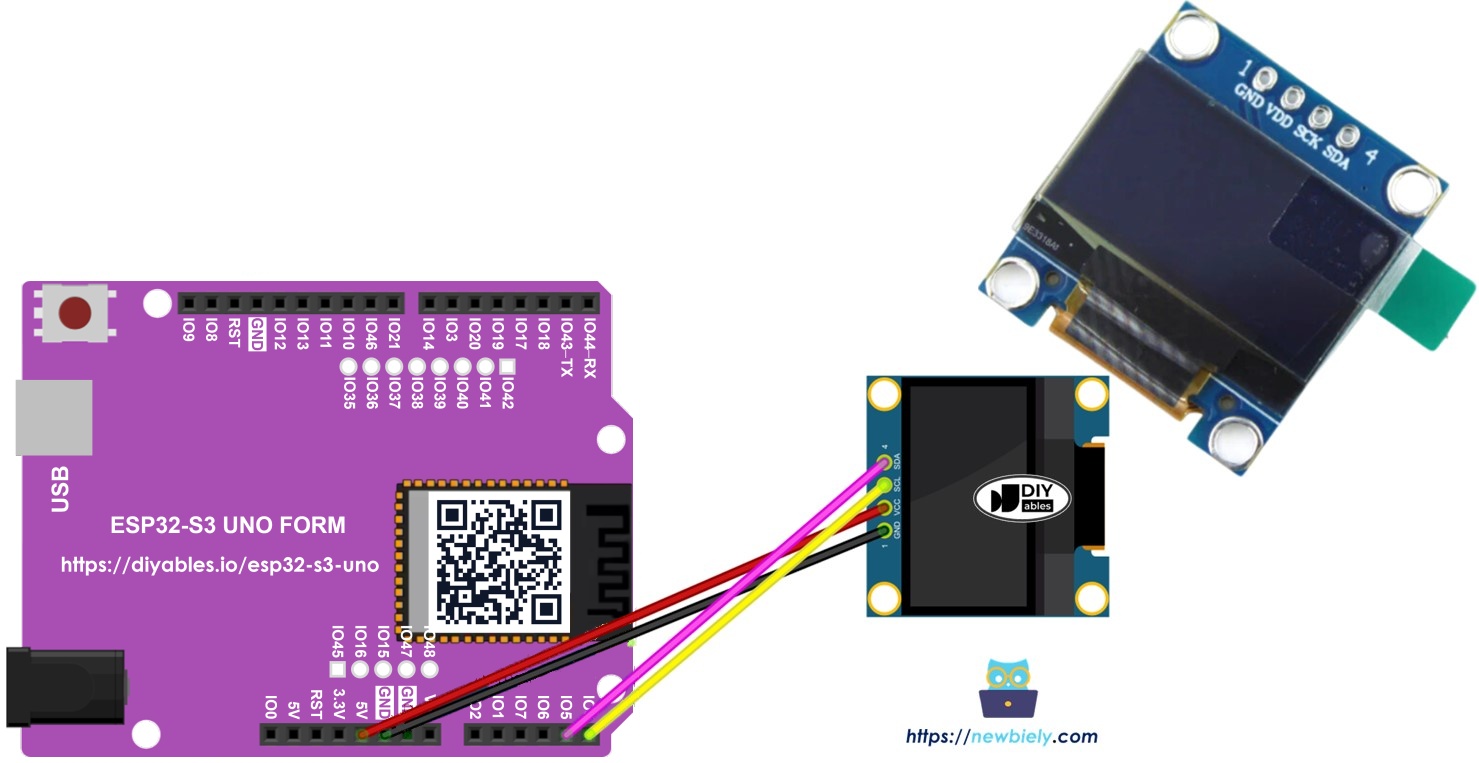
This ESP32 S3 Uno OLED tutorial shows you how to connect a 128x64 SSD1306 I2C display to the ESP32 S3 Uno form board and control it with Arduino code. You will print text and numbers, draw shapes, and show your own pictures on the small screen. The same steps work for most SSD1306 OLED I2C display modules.
In this tutorial, you will:
- Wire a 128x64 OLED I2C display to the ESP32 S3 Uno SDA and SCL pins.
- Install the Adafruit SSD1306 library in the Arduino IDE.
- Display text and numbers, and center them on the screen.
- Draw rectangles, circles and triangles on the OLED.
- Convert an image to a bitmap array and show it on the display.
Hardware Preparation
| 1 | × | ESP32 S3 Uno-form Board | |
| 1 | × | USB Cable Type-A to Type-C (for USB-A PC) | |
| 1 | × | USB Cable Type-C to Type-C (for USB-C PC) | |
| 1 | × | SSD1306 I2C OLED Display 128x64 | |
| 1 | × | Jumper Wires |
Or you can buy the following kits:
| 1 | × | DIYables Sensor Kit (18 sensors/displays) |
Additionally, some of these links are for products from our own brand, DIYables .
Buy Note: If you want a bigger OLED display, use the 2.42 inch OLED Display 128x64 .
Overview of OLED Display
Before you wire anything, it helps to know which OLED you have. OLED modules look alike, but they differ in interface, size, color and driver chip, and the code depends on these details.
Interface, size and color
OLED modules talk to the board over I2C or SPI. Common sizes are 128x64 and 128x32 pixels. The screen can be white, blue, or two-tone (for example a yellow strip on top and blue below).
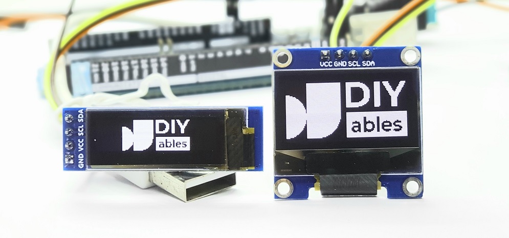
I2C or SPI?
SPI is faster, but it needs more wires on the ESP32 S3 Uno. I2C needs only two signal wires, and several I2C devices can share those same two wires. So you trade speed for fewer pins. For a small text and graphics screen, I2C is fast enough.
Driver chip
I2C OLED modules use different driver chips, such as SSD1306 and SH1106. This guide uses the 128x64 SSD1306 I2C OLED display.
I2C OLED Display Pinout
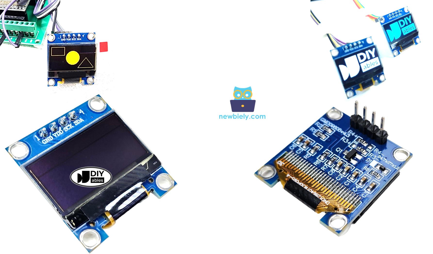
The I2C OLED module has only four pins, so the wiring is short and simple.
| Pin | Function |
|---|---|
| GND | Ground. Connect it to GND on the ESP32 S3 Uno. |
| VCC | Power supply for the display. Connect it to the 3.3V pin on the ESP32 S3 Uno. |
| SCL | Serial clock line of the I2C bus. |
| SDA | Serial data line of the I2C bus. |
※ NOTE THAT:
The pin order is not the same on every OLED module. It depends on the maker and the model. Always read the labels printed on your module before you connect the wires.
This guide is for an OLED display with the SSD1306 I2C driver. We tested it with an OLED display from DIYables, and it worked with no problems.
ESP32 S3 Uno Pinout
The image below shows the pinout of the ESP32 S3 Uno form board. Use it to find the SDA and SCL header pins and their GPIO numbers when you wire the OLED.

Wiring Diagram
The OLED connects to the I2C header pins of the ESP32 S3 Uno. Follow the diagram and the table below.
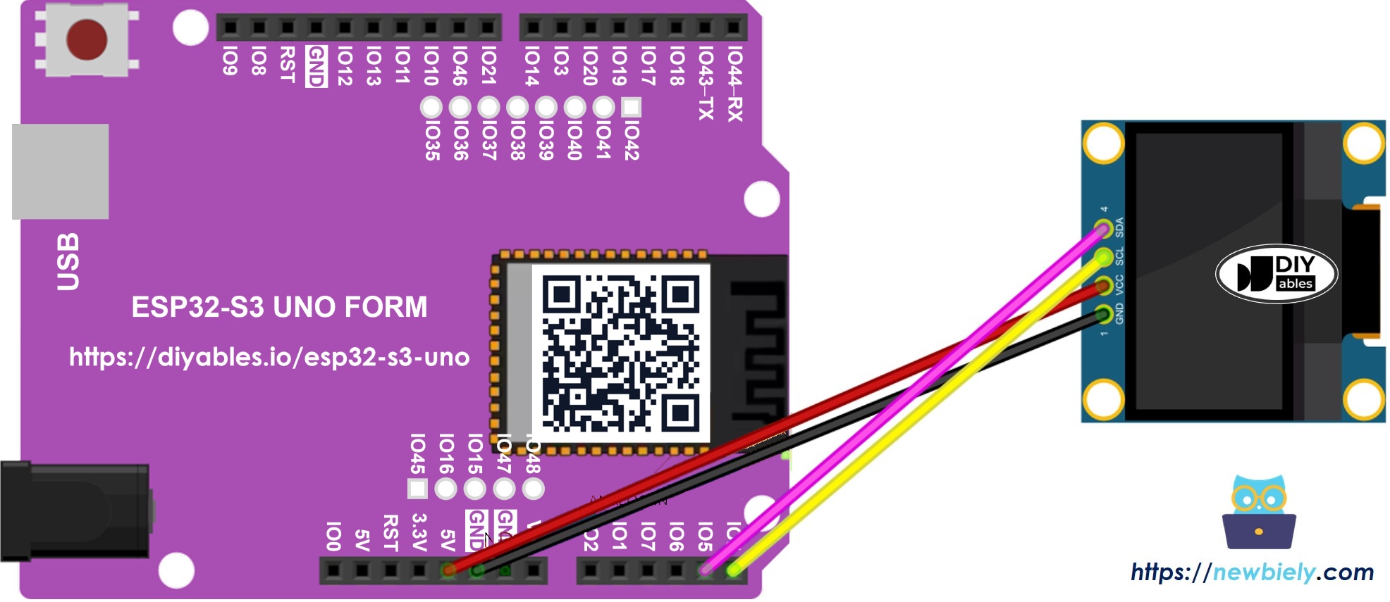
This image is created using Fritzing. Click to enlarge image
| OLED Module Pin | ESP32 S3 Uno Pin |
|---|---|
| VCC | 3.3V |
| GND | GND |
| SDA | SDA (GPIO8) |
| SCL | SCL (GPIO9) |
WARNING
On the ESP32 S3 Uno, A4 and A5 are NOT I2C pins, unlike on many other Uno-style boards. Always use the SDA (GPIO8) and SCL (GPIO9) header pins. Also, the ESP32 S3 Uno pins are NOT 5V tolerant. Many OLED modules pull SDA and SCL up to their VCC, so power the OLED from 3.3V to keep the I2C lines at a safe level.
How To Use OLED with ESP32 S3 Uno
Two things must happen before the screen shows anything. First, you install the driver library. Then you set up the display object in your sketch.
Install SSD1306 OLED library
- Open the library manager by clicking the Libraries icon on the left side of the Arduino IDE.
- Search for "SSD1306" and find the SSD1306 library by Adafruit.
- Click Install to add the library.
- Search for Adafruit SSD1306 created by Adafruit and click the Install button.
- Install the dependencies. The IDE asks to install a few more libraries, such as Adafruit GFX. Click Install All to add them all.
- Search for Adafruit GFX Library created by Adafruit and click the Install button.
How to program for OLED
Every OLED sketch in this tutorial starts with the same few lines. Once you know them, you can reuse them in any project.
Include the libraries
Set the screen size
This display is 128 pixels wide and 64 pixels tall.
Create the SSD1306 object
The object uses the Wire I2C bus. On the ESP32 S3 Uno, Wire uses GPIO8 (SDA) and GPIO9 (SCL) by default, so you do not need to set the pins. The -1 means the module has no reset pin.
Start the display in setup()
After that, you can print text, draw lines and shapes, and show pictures.
ESP32 S3 Uno Code - Display Text on OLED
This sketch starts the OLED, clears it, and prints "Hello World!" in small white text near the top of the screen. It runs once in setup(), so loop() stays empty.
Detailed Instructions
- New to the ESP32 S3 Uno? Follow ESP32 S3 Uno - Getting Started first.
- Wire it up as shown in the diagram.
- Connect the board to your computer with a USB Type-C cable.
- Open Arduino IDE, choose the ESP32S3 Dev Module board and the correct COM port.
- Install the libraries as described above.
- Copy the code and paste it into the Arduino IDE.
- Upload the code by clicking the Upload button.
- Look at the OLED. You should see "Hello World!" on the screen.
- Tip: If the screen stays black, run the I2C scanner sketch at the end of this page to check the address.
Useful text functions
The Adafruit library gives you many functions for text. These are the ones you will use most:
| Function | What it does |
|---|---|
| oled.clearDisplay() | Turns off all pixels. |
| oled.drawPixel(x, y, color) | Draws one pixel at x, y. |
| oled.setTextSize(n) | Sets the text size, from 1 to 8. |
| oled.setCursor(x, y) | Sets where the text starts. |
| oled.setTextColor(WHITE) | Makes the text white. |
| oled.setTextColor(BLACK, WHITE) | Black text on a white background. |
| oled.println("message") | Prints text. |
| oled.println(number) | Prints a number. |
| oled.println(number, HEX) | Prints a number in hexadecimal. |
| oled.display() | Sends all changes to the screen. |
| oled.startscrollright(start, stop) | Scrolls text from left to right. |
| oled.startscrollleft(start, stop) | Scrolls text from right to left. |
| oled.startscrolldiagright(start, stop) | Scrolls text diagonally, bottom-left to top-right. |
| oled.startscrolldiagleft(start, stop) | Scrolls text diagonally, bottom-right to top-left. |
| oled.stopscroll() | Stops any scrolling. |
※ NOTE THAT:
Drawing functions only change a buffer in memory. Nothing appears on the screen until you call oled.display().
How to vertical and horizontal center align text/number on OLED
Centered text looks clean, but the right position depends on the text length and size. This sketch measures the text with getTextBounds(), then places the cursor so the text sits in the middle of the screen. It shows "DIYables" and then the number 21, switching every 2 seconds.
ESP32 S3 Uno Code - Drawing on OLED
The GFX library can draw basic shapes for you. This sketch shows a rectangle, a rounded rectangle, a circle and a triangle, first as an outline and then filled. Each shape stays on the screen for 2 seconds.
ESP32 S3 Uno Code – Display Image
The OLED cannot open a JPG or PNG file. You must first turn the picture into a bitmap array, which is a list of bytes where each bit is one pixel. The free Image to Bitmap Converter tool does this for any image format. The picture below shows how the Arduino icon was converted into a bitmap array.
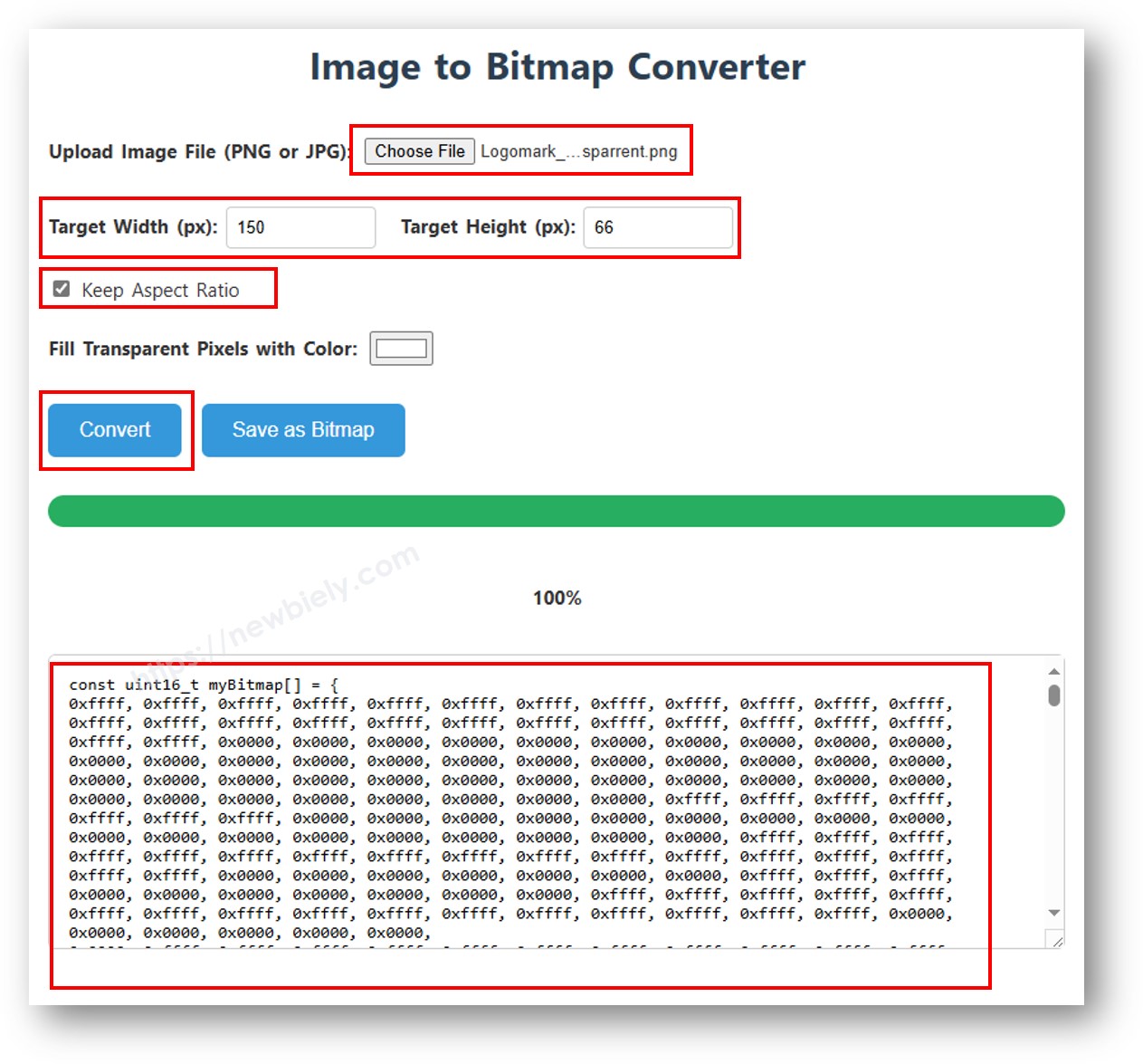
Copy the array that the tool gives you, and paste it in place of the ArduinoIcon array in the code below. The sketch draws the image, waits 2 seconds, and then inverts the colors.
※ NOTE THAT:
- The image must be the same size as the screen or smaller.
- For an OLED 128x32, resize the image first, then change the width and height in the oled.drawBitmap(); function.
OLED Troubleshooting
A blank OLED is a common problem, and the cause is usually simple. Check these points in order:
- Make sure the wiring is correct, and that SDA and SCL go to the SDA (GPIO8) and SCL (GPIO9) header pins, not to A4 and A5.
- Make sure your I2C OLED uses the SSD1306 driver.
- Check the I2C address of your OLED with the I2C address scanner code below on the ESP32 S3 Uno.
Open the Serial Monitor at 9600 baud. The output looks like this:
If the scanner shows a different address, such as 0x3D, put that address in oled.begin().
FAQ
Can I power the OLED from 5V on the ESP32 S3 Uno?
Most SSD1306 modules have a regulator and accept 3.3V to 5V. But many modules pull the SDA and SCL lines up to VCC. With 5V power, those lines can sit at 5V, and the ESP32 S3 Uno pins are NOT 5V tolerant. Power the OLED from 3.3V to be safe.
Why do A4 and A5 not work for the OLED on the ESP32 S3 Uno?
On the UNO R4, A4 and A5 double as SDA and SCL. On the ESP32 S3 Uno, A4 (GPIO5) and A5 (GPIO4) are only analog pins. The I2C bus is on the separate SDA (GPIO8) and SCL (GPIO9) header pins, and Wire.begin() uses them by default.
Do I need to change the UNO R4 OLED code for the ESP32 S3 Uno?
No. The Adafruit SSD1306 and GFX libraries work on the ESP32 S3 Uno, and the sketches in this tutorial run without changes. Just select the ESP32S3 Dev Module board in the Arduino IDE.
My OLED is an SH1106. Will this code work?
Not well. SH1106 displays need a different driver library, such as Adafruit SH110X. With the SSD1306 library, an SH1106 often shows noise or a shifted image.
Can I use more than one OLED on the same I2C bus?
Yes, if they have different addresses. Many modules have a jumper or resistor to change the address from 0x3C to 0x3D. Create one display object for each address.
What if my project needs more pins than the Uno headers give?
The ESP32 S3 Uno has two extra rows of holes with more GPIOs: GPIO15 and GPIO16 (I/O, PWM, analog), GPIO45 and GPIO35 to GPIO42 (I/O, PWM), and GPIO47/GPIO48 (output only, PWM). Solder pin headers to use them, and write the GPIO number in your code. For buttons or sensors next to the OLED, start with GPIO35 to GPIO42, or GPIO15/GPIO16 for analog sensors. Be careful with two groups of pins. First, GPIO47 and GPIO48 may run at 1.8V instead of 3.3V on some modules (especially ones with "V" in the name, like R8V or R16V), so 3.3V devices can be damaged or act strangely. Second, GPIO0, GPIO3 (D6), GPIO45 and GPIO46 (D9) are boot strapping pins, and a wrong connection can stop the board from booting or uploading code. Use the other extra pins first.
Troubleshooting
| Problem | Possible Cause | Solution |
|---|---|---|
| No COM port in the Arduino IDE | USB driver missing or board not in upload mode | Install the CP210x or CH340 driver, try another USB cable, or hold BOOT while pressing RESET |
| Upload fails with a timeout | Board did not enter download mode | Hold BOOT, press and release RESET, then release BOOT and upload again |
| OLED stays black | Wrong wiring or SDA and SCL wired to A4 and A5 | Wire SDA to SDA (GPIO8) and SCL to SCL (GPIO9), and check VCC and GND |
| Serial Monitor shows SSD1306 allocation failed | Wrong I2C address or no I2C connection | Run the I2C scanner and use the address it finds in oled.begin() |
| Scanner finds no I2C devices | Loose wires or SDA and SCL swapped | Check each jumper wire and swap SDA and SCL if needed |
| Screen shows noise or a shifted picture | Display uses an SH1106 driver | Use the Adafruit SH110X library instead of SSD1306 |
| Compile error about Adafruit_SSD1306.h | Library not installed | Install Adafruit SSD1306 and click Install All for Adafruit GFX |
| Image looks broken or cut off | Bitmap size does not match drawBitmap() | Make the image 128x64 or smaller and set the same width and height in drawBitmap() |