
ESP32 S3 UNO - DIP Switch
This ESP32 S3 Uno DIP switch tutorial shows you how to wire a DIP switch to the ESP32 S3 Uno form board and read it with Arduino code. DIP switches are small banks of slide switches. Makers use them to set a device address, pick a mode, or turn features on and off without changing the code. You will see the state of each switch, and the number they make together, in the Serial Monitor.
In this tutorial, you will:
- Learn what a DIP switch is and how its pins work
- Wire a 4-position DIP switch to the ESP32 S3 Uno
- Read the ON/OFF state of each switch with digitalRead() and INPUT_PULLUP
- Turn the switch positions into a binary number and a decimal value
- Adapt the code for 2, 6, 8 or 10-position DIP switches
Hardware Preparation
| 1 | × | ESP32 S3 Uno-form Board | |
| 1 | × | USB Cable Type-A to Type-C (for USB-A PC) | |
| 1 | × | USB Cable Type-C to Type-C (for USB-C PC) | |
| 1 | × | DIP Switch | |
| 1 | × | Breadboard | |
| 1 | × | Jumper Wires |
Or you can buy the following kits:
| 1 | × | DIYables Sensor Kit (18 sensors/displays) |
Additionally, some of these links are for products from our own brand, DIYables .
Overview of DIP Switch
A DIP switch is a simple way to give your project settings that stay in place, even after power is off. Knowing how it is built helps you wire it right the first time.
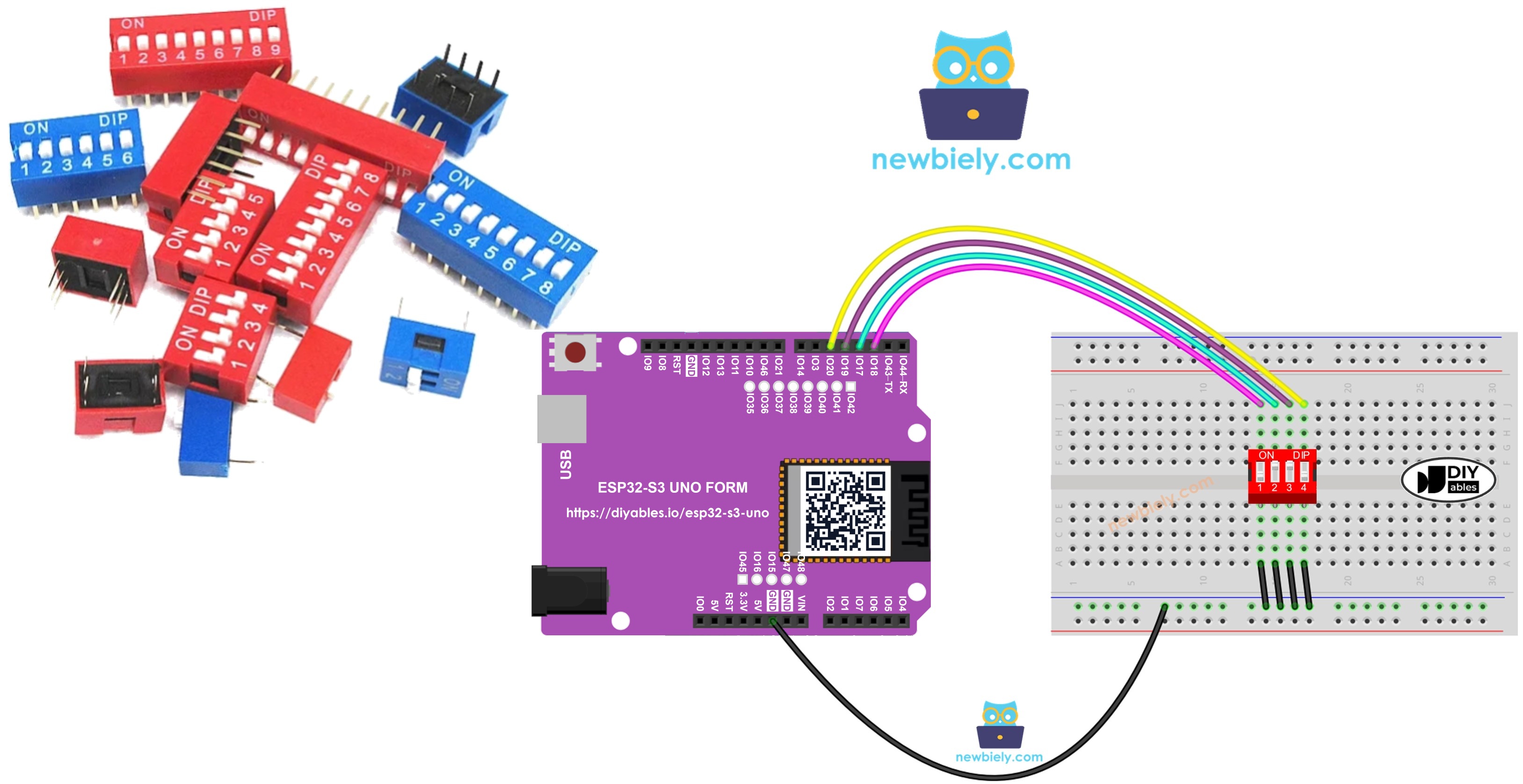
The name DIP means Dual In-line Package. One DIP switch holds several tiny slide switches in one small body. Each slide switch is called a "position". You can buy them with 2, 4, 5, 6, 8 or 10 positions.
Devices use DIP switches to set things like a device address, communication options, a security code, an operating mode or system preferences. Because each position is ON or OFF, every position works like one bit of a number. By sliding the switches, you choose the number you want.
Pinout
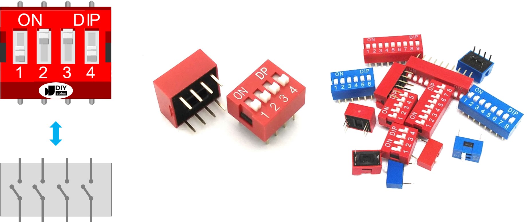
A DIP switch has two rows of pins. Each row has one pin per position, so a 4-position DIP switch has 8 pins, 4 on each side. The two pins that face each other belong to the same slide switch. The sides are interchangeable, so it does not matter which row you connect to the board and which row you connect to GND.
How It Works
Each position is just a simple on/off contact. Once you know what ON and OFF mean in the circuit, the code becomes easy to follow.
ON position
The switch is closed. Current can flow from one pin to the other.
OFF position
The switch is open. The connection is broken and no current can flow.
Reading it with the ESP32 S3 Uno
In this project, one side of each switch goes to GND and the other side goes to an ESP32 S3 Uno pin set as a pull-up input. The internal pull-up resistor keeps the pin HIGH when the switch is open. When you slide the switch ON, the pin is pulled to GND and reads LOW. The table below sums it up.
| DIP switch position | Binary representation | Circuit state | ESP32 S3 Uno pin state |
|---|---|---|---|
| ON | 1 | CLOSED | LOW |
| OFF | 0 | OPEN | HIGH |
The examples below use a 4-position DIP switch. You can easily change them for 2, 3, 5, 6, 8 or 10-position DIP switches.
ESP32 S3 Uno Pinout
The image below shows the pinout of the ESP32 S3 Uno form board. Use it to find the Uno header pins (D2, D3, D4, D5…) and their GPIO numbers when you wire the DIP switch.

Wiring Diagram
Connect one row of the DIP switch to four digital pins, and the other row to GND. No external resistors are needed, because the code turns on the internal pull-up resistors.
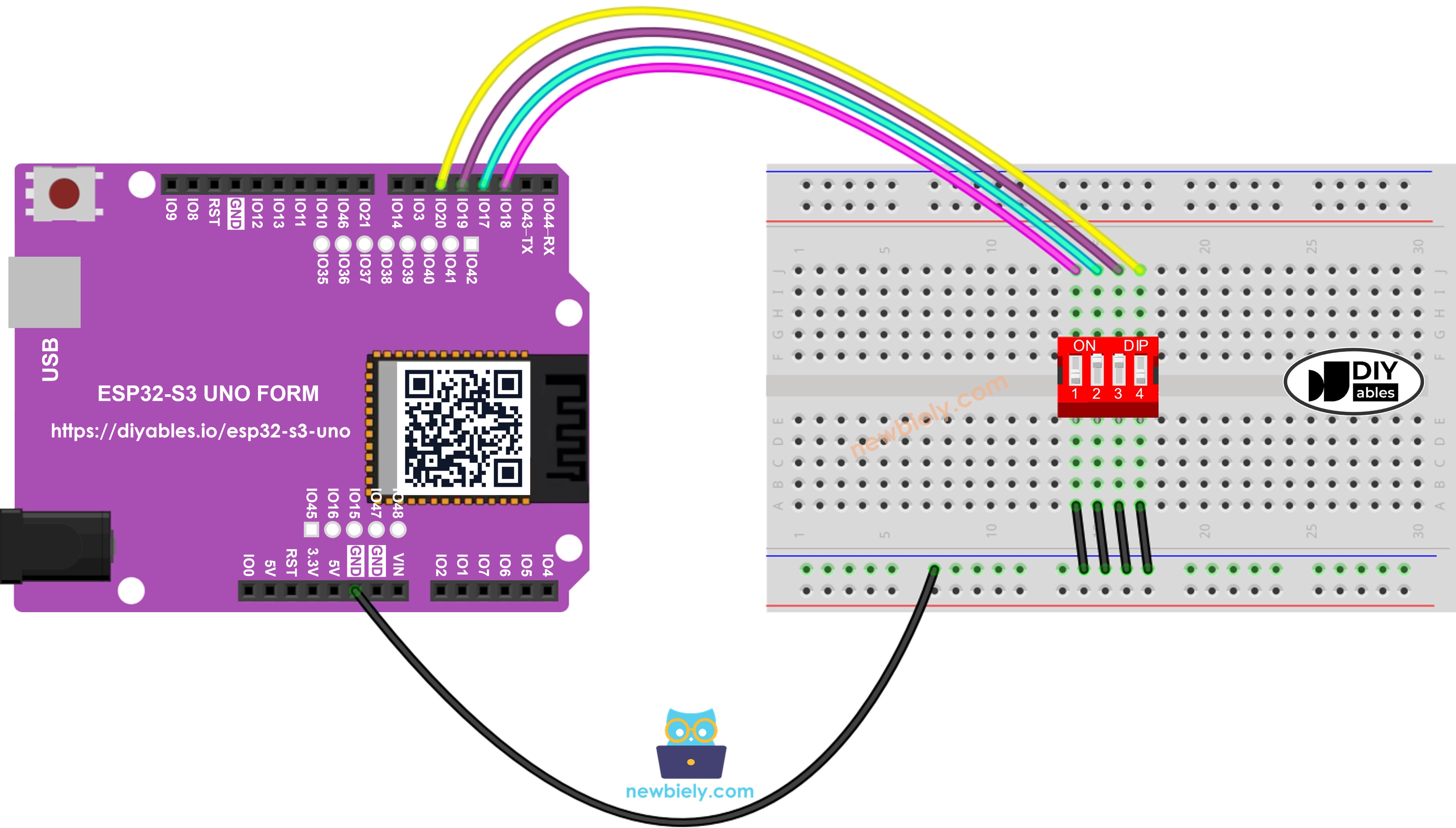
This image is created using Fritzing. Click to enlarge image
| DIP Switch Pin | ESP32 S3 Uno Pin |
|---|---|
| Position 1 (one side) | D2 (GPIO18) |
| Position 2 (one side) | D3 (GPIO17) |
| Position 3 (one side) | D4 (GPIO19) |
| Position 4 (one side) | D5 (GPIO20) |
| All pins on the other side | GND |
ESP32 S3 Uno Code - DIP Switch
There are two sketches below. The first one tells you whether each switch is ON or OFF. The second one combines all positions into a single number, which is how DIP switches are used in real devices.
ESP32 S3 Uno code - Reading the ON/OFF state of the DIP switch
This sketch sets the four pins as INPUT_PULLUP inputs. Every half second, it reads each pin and prints "ON" when the pin is LOW and "OFF" when it is HIGH. Note that the code uses GPIO numbers (18, 17, 19, 20), not the Uno labels D2 to D5.
Detailed Instructions
- New to the ESP32 S3 Uno? Follow ESP32 S3 Uno - Getting Started first.
- Wire it up as shown in the diagram.
- Connect the board to your computer with a USB Type-C cable.
- Open Arduino IDE, choose the ESP32S3 Dev Module board and the correct COM port.
- Copy the code above and paste it into Arduino IDE.
- Upload the code by clicking the Upload button.
- Open the Serial Monitor and set the baud rate to 9600.
- Slide the switches ON one at a time and watch the output change.
- Tip: If every position shows OFF, check that the other side of the DIP switch is really connected to GND.
ESP32 S3 Uno code - Encoding the states of DIP switch into a number
This sketch treats each position as one bit. Position 1 is the highest bit and position 4 is the lowest bit. When a switch is ON, the code sets its bit with a shift and an OR, then prints the final value as a decimal number.
Detailed Instructions
- New to the ESP32 S3 Uno? Follow ESP32 S3 Uno - Getting Started first.
- Wire it up as shown in the diagram.
- Connect the board to your computer with a USB Type-C cable.
- Open Arduino IDE, choose the ESP32S3 Dev Module board and the correct COM port.
- Copy the code above and upload it to the ESP32 S3 Uno.
- Open the Serial Monitor at 9600 baud.
- Slide the switches into different positions and watch the number change.
- Tip: Want more positions? Change POSITION_NUM and add more GPIO numbers to SWITCH_PINS[].
The number depends on which slide switches are ON. The table below shows every combination for a 4-position DIP switch and the value the ESP32 S3 Uno prints.
| Position-1 | Position-2 | Position-3 | Position-4 | Binary Value | Decimal Value |
|---|---|---|---|---|---|
| OFF | OFF | OFF | OFF | 0000 | 0 |
| OFF | OFF | OFF | ON | 0001 | 1 |
| OFF | OFF | ON | OFF | 0010 | 2 |
| OFF | OFF | ON | ON | 0011 | 3 |
| OFF | ON | OFF | OFF | 0100 | 4 |
| OFF | ON | OFF | ON | 0101 | 5 |
| OFF | ON | ON | OFF | 0110 | 6 |
| OFF | ON | ON | ON | 0111 | 7 |
| ON | OFF | OFF | OFF | 1000 | 8 |
| ON | OFF | OFF | ON | 1001 | 9 |
| ON | OFF | ON | OFF | 1010 | 10 |
| ON | OFF | ON | ON | 1011 | 11 |
| ON | ON | OFF | OFF | 1100 | 12 |
| ON | ON | OFF | ON | 1101 | 13 |
| ON | ON | ON | OFF | 1110 | 14 |
| ON | ON | ON | ON | 1111 | 15 |
Video Tutorial
Watch the video below to see this ESP32 S3 Uno project step by step.
FAQ
Do I need resistors to connect a DIP switch to the ESP32 S3 Uno?
No. The code uses INPUT_PULLUP, which turns on the internal pull-up resistor of each pin. The pin reads HIGH when the switch is OFF and LOW when it is ON. Just connect the other side of the DIP switch to GND.
Why does the code use 18, 17, 19 and 20 instead of 2, 3, 4 and 5?
On the ESP32 S3 Uno, the header labels are not the same as the GPIO numbers. D2 is GPIO18, D3 is GPIO17, D4 is GPIO19 and D5 is GPIO20. The code must use the GPIO numbers. If you write 2, 3, 4 and 5, the board reads different pins and the switches seem to do nothing.
Can I connect the DIP switch to 5V instead of GND?
No. ESP32 S3 Uno pins work at 3.3V and are not 5V tolerant. With the wiring in this tutorial, the switches only connect pins to GND, so no voltage ever goes into the board. This is the safest way to use a DIP switch.
Why is ON read as LOW?
With a pull-up input, the pin stays HIGH until something pulls it to GND. Sliding a switch ON connects the pin to GND, so it reads LOW. That is why the code defines ON as LOW and OFF as HIGH.
How do I use an 8-position DIP switch?
Set POSITION_NUM to 8 and add four more GPIO numbers to SWITCH_PINS[], for example D7 (GPIO14), D8 (GPIO21), D10 (GPIO10) and D11 (GPIO11). The encoded value will then go from 0 to 255. Avoid D0/D1, and avoid D6 and D9 because they are boot strapping pins.
What if my project needs more pins than the Uno headers give?
The ESP32 S3 Uno has two extra rows of holes with more GPIOs: GPIO15 and GPIO16 (I/O, PWM, analog), GPIO45 and GPIO35 to GPIO42 (I/O, PWM), and GPIO47/GPIO48 (output only, PWM). Solder pin headers to use them and write the GPIO number in code. For a large DIP switch, GPIO35 to GPIO42 and GPIO15/GPIO16 are good inputs. Do not use GPIO47/GPIO48, because they are output only. Be careful: GPIO47 and GPIO48 may run at 1.8V instead of 3.3V on some modules (especially ones with "V" in the name, like R8V or R16V), so 3.3V devices can be damaged or act strangely. Also, GPIO0, GPIO3 (D6), GPIO45 and GPIO46 (D9) are boot strapping pins, and a wrong connection can stop the board from booting or uploading code. Use the other extra pins first.
Troubleshooting
| Problem | Possible Cause | Solution |
|---|---|---|
| No COM port in Arduino IDE | USB driver missing or board not in upload mode | Install the CP210x or CH340 driver, or hold BOOT while pressing RESET, then upload again |
| All positions always show OFF | Other side of the DIP switch is not connected to GND | Connect every pin on the other row to a GND pin and check the breadboard rows |
| One position never changes | Wire on the wrong pin or loose jumper | Check that positions 1 to 4 go to D2, D3, D4 and D5 |
| Switches seem to do nothing | Code uses Uno numbers 2, 3, 4, 5 instead of GPIO numbers | Use 18, 17, 19 and 20 in SWITCH_PINS |
| Values jump randomly | Pins set as INPUT without pull-up | Keep pinMode set to INPUT_PULLUP |
| Encoded number is reversed | Bit order differs from what you expect | Position 1 is the highest bit, so swap the order of SWITCH_PINS if you need the other way |
| Serial Monitor shows strange characters | Wrong baud rate | Set the Serial Monitor to 9600 baud |