
ESP32 S3 UNO - Ultrasonic Sensor
This ESP32 S3 Uno ultrasonic sensor tutorial shows you how to wire an HC-SR04 to the ESP32 S3 Uno form board and measure distance with Arduino code. The HC-SR04 is a low-cost distance sensor that works with sound you cannot hear. When you finish, the Serial Monitor will show the distance to your hand in centimeters, with clean and stable values.
In this tutorial, you will:
- Learn how the HC-SR04 ultrasonic sensor measures distance
- Wire the HC-SR04 safely to the 3.3V pins of the ESP32 S3 Uno
- Send a trigger pulse and read the echo with pulseIn()
- Convert the echo time into a distance in centimeters
- Remove noise from the distance readings with a simple filter
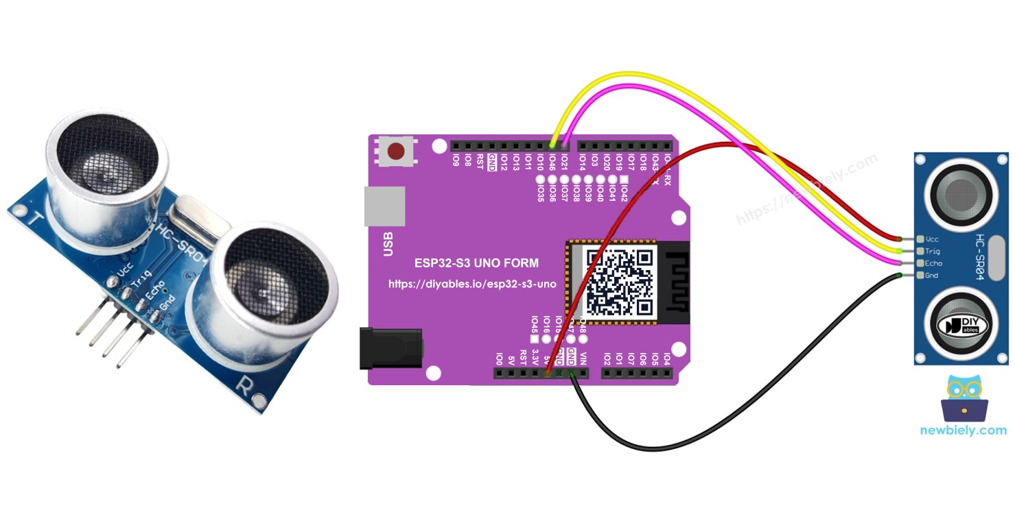
Hardware Preparation
| 1 | × | ESP32 S3 Uno-form Board | |
| 1 | × | USB Cable Type-A to Type-C (for USB-A PC) | |
| 1 | × | USB Cable Type-C to Type-C (for USB-C PC) | |
| 1 | × | Ultrasonic Sensor | |
| 1 | × | Jumper Wires | |
| 1 | × | 5V to 3.3V Level Converter |
Or you can buy the following kits:
| 1 | × | DIYables Sensor Kit (18 sensors/displays) |
Additionally, some of these links are for products from our own brand, DIYables .
Overview of Ultrasonic Sensor
Before you wire anything, it helps to know how the sensor "sees" an object. Once you understand the idea, the code becomes easy to follow.
The HC-SR04 sends out a short burst of ultrasonic sound, which is too high for people to hear. The sound travels through the air, hits an object, and bounces back to the sensor. The sensor measures how long the round trip takes. Since sound moves at a known speed, this time tells you how far away the object is.
The math is simple. Sound travels about 0.034 cm per microsecond. The echo time covers the trip to the object and back, so you divide by 2. That gives distance (cm) = 0.017 × echo time (µs).
Pinout
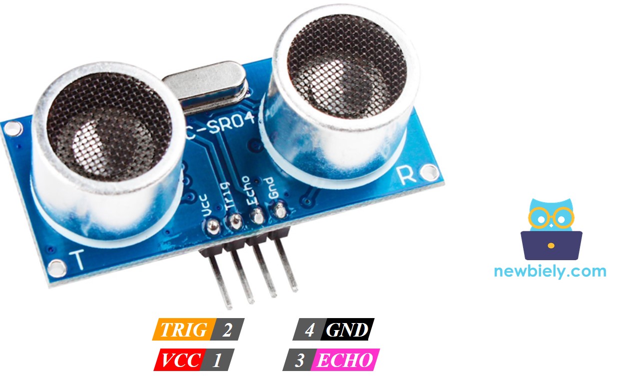
The HC-SR04 has four pins. Two are for power, and two are for the signals that the ESP32 S3 Uno uses to start a measurement and read the result.
VCC pin
Connect it to 5V. The HC-SR04 needs 5V to work well.
GND pin
Connect it to GND (0V).
TRIG pin
The ESP32 S3 Uno sends a short 10 µs pulse to this pin to start a measurement. A 3.3V pulse from the board is high enough for the sensor.
ECHO pin
The sensor sends a pulse back on this pin. The pulse length equals the time the sound took to go out and come back. The ESP32 S3 Uno measures this pulse to find the distance. Note that this pulse is 5V, so it needs care on a 3.3V board (see the wiring section).
ESP32 S3 Uno Pinout
The image below shows the pinout of the ESP32 S3 Uno form board. Use it to find the Uno header pins (D8, D9, 5V…) and their GPIO numbers while you wire the sensor.

Wiring Diagram
The sensor uses only four wires. Power comes from the 5V header, TRIG goes to D9 and ECHO goes to D8.
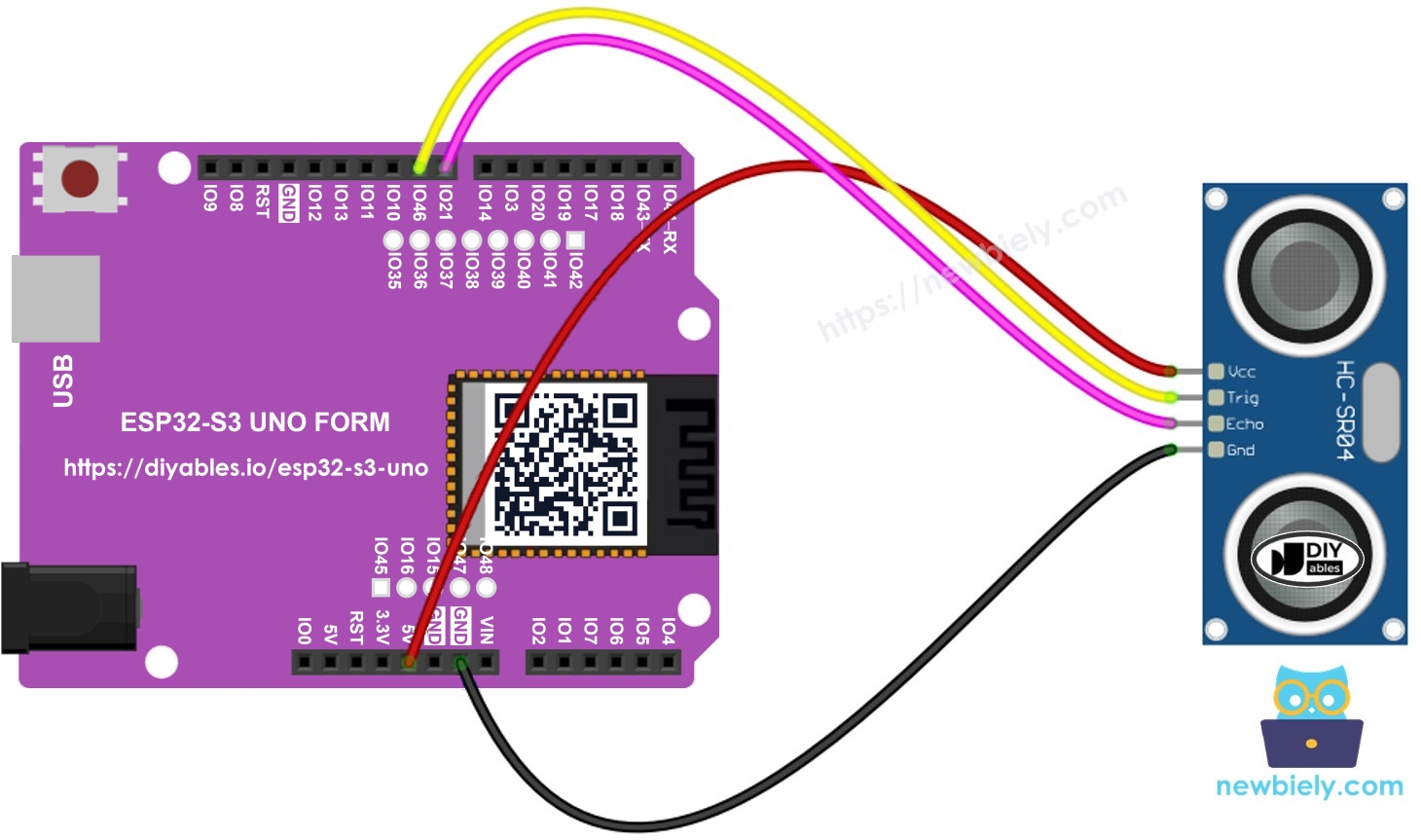
This image is created using Fritzing. Click to enlarge image
| Ultrasonic Sensor Pin | ESP32 S3 Uno Pin |
|---|---|
| VCC | 5V |
| GND | GND |
| TRIG | D9 (GPIO46) |
| ECHO | D8 (GPIO21) through a level converter or voltage divider |
WARNING
The HC-SR04 runs at 5V, so its ECHO pin outputs a 5V pulse. ESP32 S3 Uno pins are NOT 5V tolerant, and a direct 5V signal can damage GPIO21 over time. Put a 5V to 3.3V level converter between ECHO and D8. You can also use a simple voltage divider: a 1kΩ resistor from ECHO to D8, and a 2kΩ resistor from D8 to GND. The TRIG line is safe, because it goes from the board to the sensor.
WARNING
TRIG uses D9 (GPIO46), which is a boot strapping pin on the ESP32 S3 Uno. The chip checks this pin at startup to choose its boot mode. The HC-SR04 TRIG input does not pull the pin up, so it normally works fine. If the board does not boot or code does not upload, unplug the TRIG wire, upload again, and then plug it back in.
ESP32 S3 Uno Code
This sketch sends a 10 µs pulse to the TRIG pin, then uses pulseIn() to measure how long the ECHO pin stays HIGH. It turns that time into centimeters and prints the result to the Serial Monitor twice per second. Note that the code uses the GPIO numbers (46 and 21), not the header names D9 and D8.
Detailed Instructions
Follow these steps to run the sketch on your board:
- New to the ESP32 S3 Uno? Follow ESP32 S3 Uno - Getting Started first.
- Wire it up as shown in the diagram, with the level converter or divider on the ECHO line.
- Connect the board to your computer with a USB Type-C cable.
- Open Arduino IDE, choose the ESP32S3 Dev Module board and the correct COM port.
- Copy the code above and paste it into Arduino IDE.
- Upload the code to the ESP32 S3 Uno by clicking the Upload button.
- Open the Serial Monitor at 9600 baud.
- Move your hand slowly toward the sensor and away from it.
- Watch the distance change on the Serial Monitor.
- Tip: Hold a flat object, like a book, in front of the sensor. Flat and hard surfaces reflect sound much better than a hand or soft cloth.
Code Explanation
Each important line in the ESP32 S3 Uno code above has a comment. Read them from top to bottom: the pin setup, the trigger pulse, the echo measurement with pulseIn(), and the distance formula 0.017 × duration.
How to Filter Noise from Distance Measurements of Ultrasonic Sensor
Raw ultrasonic readings are not always clean. Echoes from other objects or a soft surface can give a value that is far too small or too large. If your project makes a decision from one bad reading, it can act the wrong way.
A simple fix is to take many readings and throw away the extreme ones. The sketch below works like this:
- Take 20 measurements and store them in an array.
- Sort the array from the smallest value to the largest.
- Ignore the 5 smallest values and the 5 largest values, because they are most likely noise.
- Average the 10 values in the middle (index 5 to 14) to get the final distance.
Each reading waits 30 ms, so one filtered value takes about 0.6 seconds. This short wait stops one sound burst from mixing with the echo of the next one.
Video Tutorial
Watch the video below to see this ESP32 S3 Uno project step by step.
The video project adds a traffic light module and a buzzer. The closer the object, the faster the beeps and the "hotter" the light color. Here is the full code for the ESP32 S3 Uno:
In this sketch the traffic light uses D5 (GPIO20), D6 (GPIO3) and D7 (GPIO14), and the buzzer uses D10 (GPIO10).
WARNING
D6 (GPIO3) is a boot strapping pin on the ESP32 S3 Uno. An LED on this pin is usually fine, but if the board fails to boot or upload, disconnect the yellow LED wire and try again.
Ultrasonic Sensor Applications
An ultrasonic sensor is useful in any project that needs to know "how far" without touching anything. Here are some common ideas you can build with the ESP32 S3 Uno:
- Avoiding collisions in a small robot car
- Detecting when a bin or box is full
- Measuring the water level in a tank
- Detecting when a person comes close to a device
Function References
FAQ
Can I connect the HC-SR04 directly to the ESP32 S3 Uno?
VCC, GND and TRIG can go directly to the board. The ECHO pin is the problem, because it outputs 5V and ESP32 S3 Uno pins are not 5V tolerant. Use a level converter or a 1kΩ / 2kΩ voltage divider on the ECHO line. The UNO R4 is a 5V board and does not need this, which is a key difference.
Can I power the HC-SR04 from 3.3V instead?
The standard HC-SR04 is made for 5V. At 3.3V it often gives wrong values or no echo at all. Some newer versions (such as the HC-SR04+ or RCWL-9610) work at 3.3V, and then the ECHO output is also 3.3V, so no divider is needed. Check your module's datasheet first.
Why does the code use 46 and 21 instead of D9 and D8?
On the ESP32 S3 Uno, the header labels are not the pin numbers in code. D9 is GPIO46 and D8 is GPIO21. Always write the GPIO number in your sketch.
What is the measuring range of the HC-SR04?
It measures from about 2 cm to 400 cm, with a beam angle of about 15 degrees. Below 2 cm the echo returns too fast to measure. Far away or soft objects may not reflect enough sound, so readings at long range are less reliable.
Why do I sometimes get 0 cm?
pulseIn() returns 0 when no echo arrives before its timeout (about 1 second by default). This happens when nothing is in range, the object absorbs sound, or the ECHO wire is loose. Use the noise filter sketch, or ignore 0 values in your code.
What if my project needs more pins than the Uno headers give?
The ESP32 S3 Uno has two extra rows of holes with more GPIOs. GPIO15 and GPIO16 support I/O, PWM and analog. GPIO45 and GPIO35 to GPIO42 support I/O and PWM. GPIO47 and GPIO48 are output only, with PWM. Solder pin headers to use them and write the GPIO number in your code. For a second ultrasonic sensor, GPIO35 to GPIO42 are a good choice. You could use GPIO47 or GPIO48 for TRIG, but never for ECHO, because they cannot be inputs. Keep two warnings in mind. First, GPIO47 and GPIO48 may run at 1.8V instead of 3.3V on some modules (especially ones with "V" in the name, like R8V or R16V), so 3.3V devices can be damaged or act strangely. Second, GPIO0, GPIO3 (D6), GPIO45 and GPIO46 (D9) are boot strapping pins, and a wrong connection can stop the board from booting or uploading code. Use the other extra pins first.
Troubleshooting
| Problem | Possible Cause | Solution |
|---|---|---|
| No COM port shows up in Arduino IDE | USB driver missing or board not in upload mode | Install the CP210x or CH340 driver, use a data USB cable, or hold BOOT while pressing RESET |
| Board does not boot or upload fails | Wire on boot strapping pin D9 (GPIO46) | Unplug the TRIG wire, upload the code, then plug it back in |
| Distance is always 0 | No echo, loose ECHO wire or broken divider | Check the ECHO path to D8 and make sure an object is within 2 to 400 cm |
| Readings are wrong or very unstable | Sensor powered from 3.3V or weak USB power | Power VCC from the 5V header and use a good USB cable |
| Values jump around a lot | Noise from echoes or soft surfaces | Use the noise filter sketch and aim at a flat hard object |
| Nothing prints on the Serial Monitor | Wrong baud rate | Set the Serial Monitor to 9600 baud |
| Distance never changes | Wrong GPIO numbers in code | Use 46 for TRIG and 21 for ECHO, not 9 and 8 |
| Board resets or pin acts strange | 5V ECHO signal goes straight into the pin | Add a level converter or a 1kΩ and 2kΩ voltage divider |