
ESP32 S3 UNO - MAX6675 Thermocouple Module
This ESP32 S3 Uno MAX6675 tutorial shows you how to connect a MAX6675 thermocouple module to the ESP32 S3 Uno form board and read its temperature with Arduino code. A Type-K thermocouple can handle heat that would destroy a normal sensor, and the MAX6675 turns its tiny signal into a clean digital value. You will see the temperature in both Celsius and Fahrenheit on the Serial Monitor.
In this tutorial, you will:
- Learn how a Type-K thermocouple and the MAX6675 chip work together
- Wire the MAX6675 thermocouple module to the ESP32 S3 Uno
- Install the MAX6675 library in Arduino IDE
- Read the high temperature sensor value in °C and °F
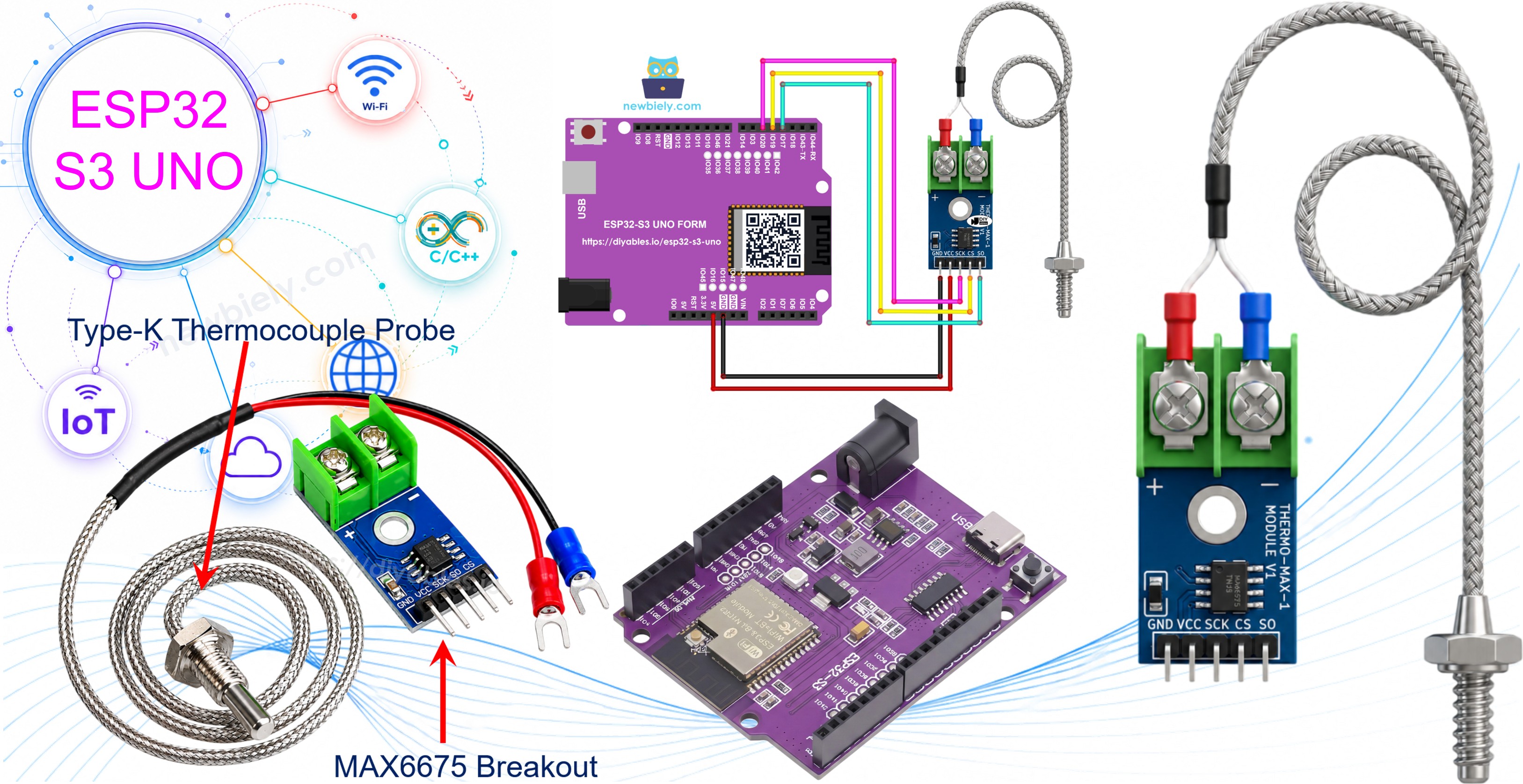
Hardware Preparation
| 1 | × | ESP32 S3 Uno-form Board | |
| 1 | × | USB Cable Type-A to Type-C (for USB-A PC) | |
| 1 | × | USB Cable Type-C to Type-C (for USB-C PC) | |
| 1 | × | MAX6675 Thermocouple Module | |
| 1 | × | Jumper Wires |
Or you can buy the following kits:
| 1 | × | DIYables Sensor Kit (18 sensors/displays) |
Additionally, some of these links are for products from our own brand, DIYables .
Overview of MAX6675 Thermocouple Module
Sensors like the DHT11, DS18B20, LM35 or TMP36 are great for room temperature. But they cannot measure something as hot as molten lava (well over 1000°C or 1800°F) or as cold as liquid nitrogen (around −195.8°C or −320°F). A thermocouple can, and the MAX6675 module makes it easy to read one.
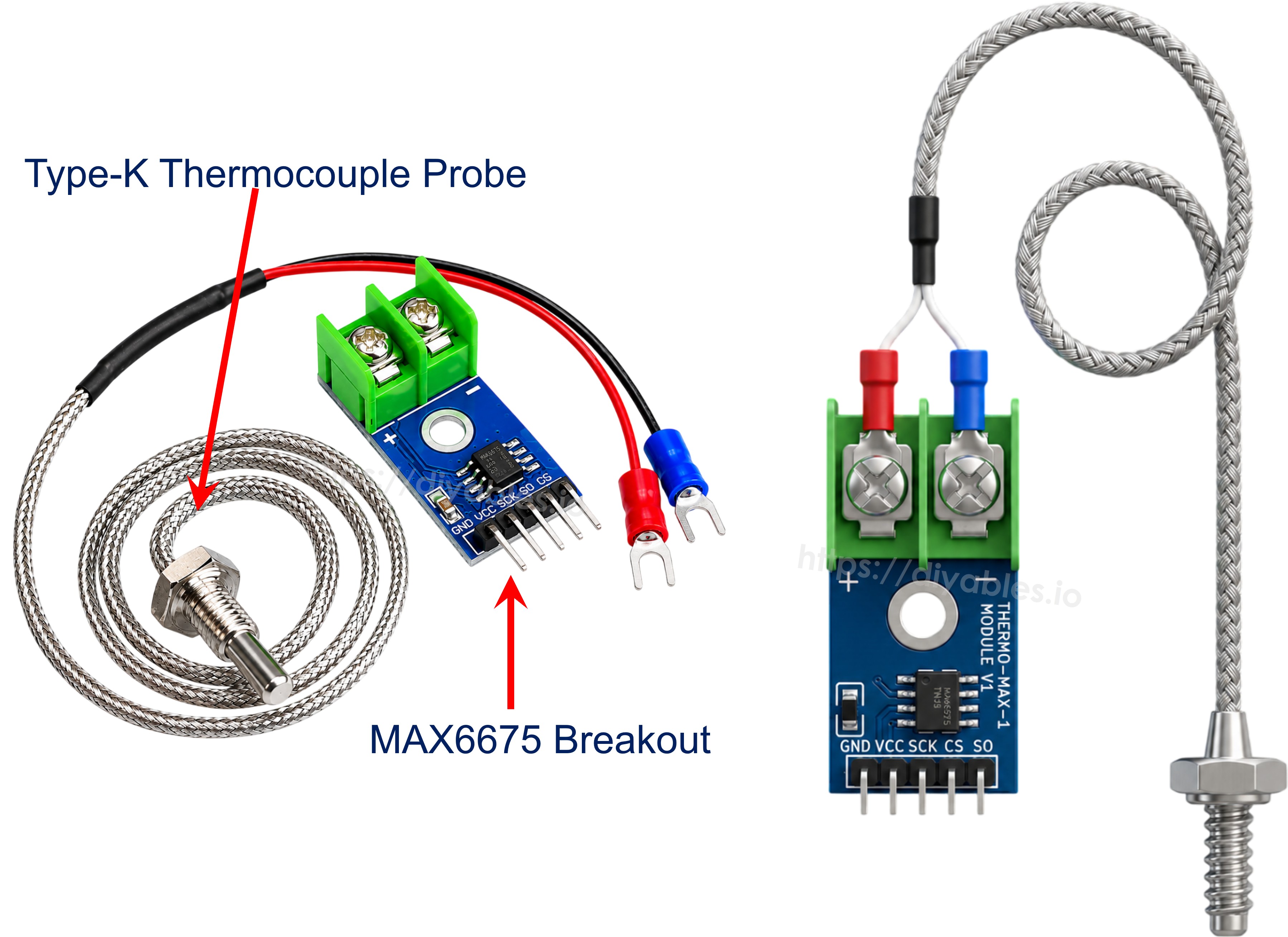
The module comes as a set: a small MAX6675 breakout board and a Type-K thermocouple probe.
Basics of Thermocouples
A thermocouple is two wires made of different metals, joined at one end. This joined end is called the hot junction. When it gets hotter or colder, the pair makes a very small voltage, and that voltage follows the temperature. Because there is no chip at the tip, a thermocouple survives temperatures that would kill other sensors. In general, thermocouples can cover about -330°F to +2460°F.
There are several thermocouple types, such as J, K, E and T. Each type uses a different pair of metals. Type-K is the most popular one. It uses Chromel and Alumel wires and covers roughly -328°F to +2300°F.
The voltage from a thermocouple is only a few microvolts per degree. It is too small to read directly with the ESP32 S3 Uno ADC. That is the job of the MAX6675 chip: it measures this voltage and turns it into a temperature number for you.
MAX6675 Module Pinout
The breakout board reads the probe, converts the signal into a temperature, and sends it to the ESP32 S3 Uno over an SPI-style interface. It measures from 0°C to +1024°C with an accuracy of about ±3°C, and it runs on 3.0V to 5.5V.
Power pins
VCC is the power input (3V to 5V). GND goes to ground. On the ESP32 S3 Uno, power the module from 3.3V.
Data pins
SCK is the clock pin. CS is the chip select pin, which tells the module when to send data. SO is the data output pin: it sends the temperature reading to the ESP32 S3 Uno.
Probe terminal
On the other side of the board is a 2-pin screw terminal for the probe. Connect the red wire to + and the blue wire to -.
Type-K Thermocouple Probe
The probe that comes with the module is about 18 inches long. It is rated for 0°C to 80°C. The red wire is the positive lead and the blue wire is the negative lead. If you want to measure much higher temperatures, use a probe rated for that range.
Technical Specifications
| MAX6675 Module | |
|---|---|
| Operating Voltage | 3.0V to 5.5V |
| Interface | SPI (read only) |
| Temperature Range (MAX6675) | 0 to 1024°C |
| Temperature Range (supplied probe) | 0 to 80°C |
| Accuracy | ±3°C |
ESP32 S3 Uno Pinout
The image below shows the pinout of the ESP32 S3 Uno form board. Use it to find the Uno header pins (D3, D4, D5, 3.3V) and their GPIO numbers when you wire the module.

Wiring Diagram
The module needs power and three digital pins for its data lines. Wire it as shown below, then screw the probe into the terminal block: red wire to '+' and blue wire to '-'.
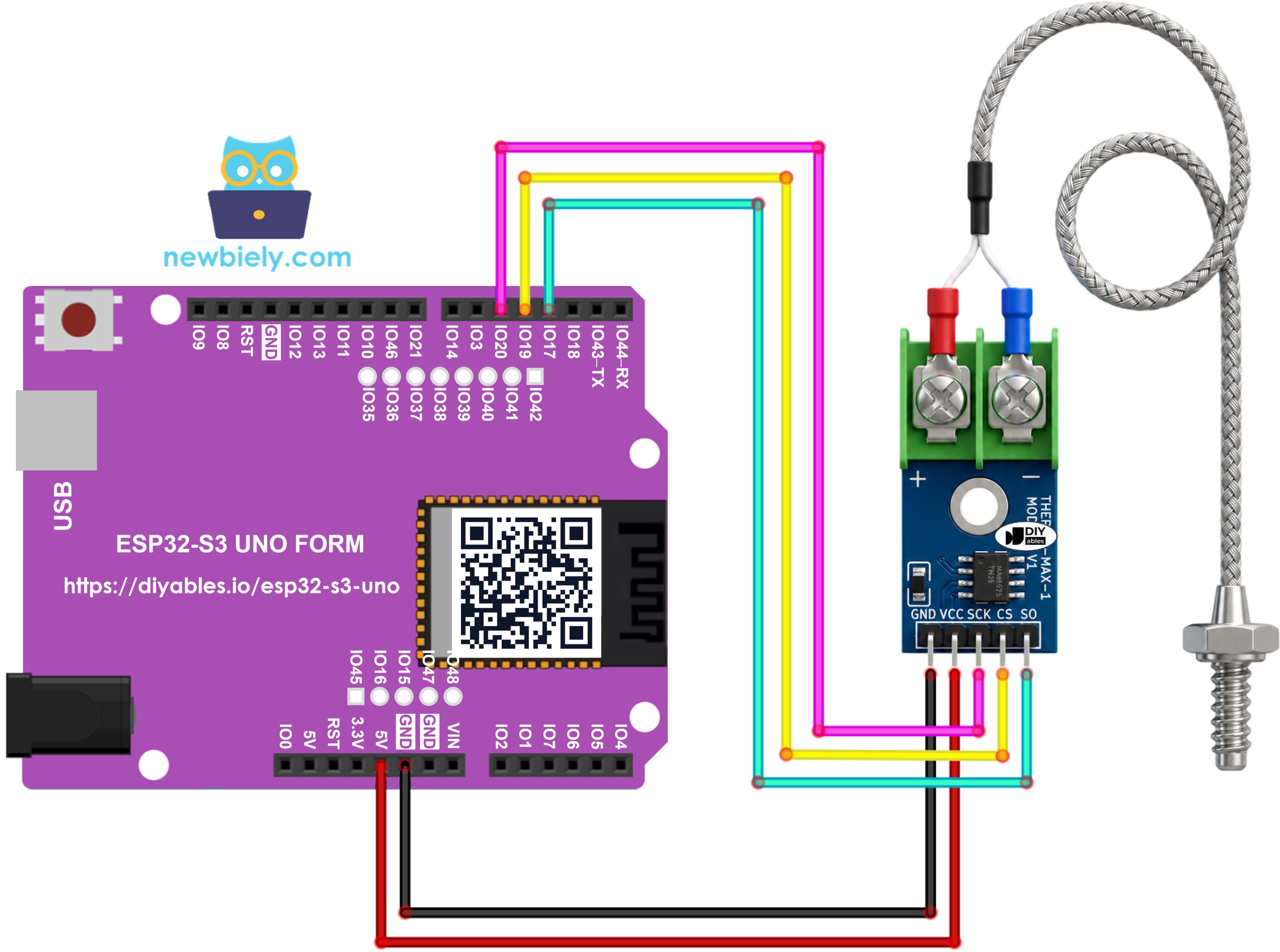
This image is created using Fritzing. Click to enlarge image
Wiring table of MAX6675 Module and ESP32 S3 Uno
| MAX6675 Module | ESP32 S3 Uno Pin |
|---|---|
| VCC | 3.3V |
| GND | GND |
| SCK | D5 (GPIO20) |
| CS | D4 (GPIO19) |
| SO | D3 (GPIO17) |
WARNING
The ESP32 S3 Uno pins are NOT 5V tolerant. The SO pin of the MAX6675 outputs a signal at the same level as its VCC. If you power the module from 5V, the SO pin sends 5V into D3 (GPIO17), which can damage the board over time. Power the module from 3.3V instead. The MAX6675 works fine from 3.0V, so you lose nothing.
ESP32 S3 Uno Code
The sketch creates a MAX6675 object on three pins and reads the temperature once per second. It prints each reading in Celsius and Fahrenheit on the Serial Monitor.
Detailed Instructions
Follow these steps in order:
- New to the ESP32 S3 Uno? Follow ESP32 S3 Uno - Getting Started first.
- Wire it up as shown in the diagram, with VCC on 3.3V.
- Connect the board to your computer with a USB Type-C cable.
- Open Arduino IDE, choose the ESP32S3 Dev Module board and the correct COM port.
- Open the Library Manager by clicking the Libraries icon on the left side of Arduino IDE.
- Install the library: search for "MAX6675", find the library by Adafruit, and click Install.
- Search for MAX6675 library created by Adafruit and click the Install button.
- Copy the code above and paste it into Arduino IDE.
- Upload the code by clicking the Upload button.
- Touch the probe to the object you want to measure.
- Open the Serial Monitor and set it to 9600 baud.
- Check the result. The temperature updates every second:
- Tip: hold the probe tip between your fingers. The value should rise slowly toward your skin temperature, which is a quick way to check that everything works.
※ NOTE THAT:
If the value never changes or looks wrong, check the three data wires between the module and the ESP32 S3 Uno first. Then make sure the probe wires are tight in the '+' and '-' terminals and not swapped.
Code Explanation
The first line includes the MAX6675 library. This library does all the low-level work of talking to the chip, so your sketch stays short.
Next, three variables hold the GPIO numbers for the module's SO, CS and SCK pins. On the ESP32 S3 Uno, the header pins D3, D4 and D5 are GPIO17, GPIO19 and GPIO20, so the code uses those numbers.
Then the sketch builds a MAX6675 object called thermocouple. You pass the pins in this order: SCK, CS, SO.
In setup(), the Serial Monitor starts at 9600 baud. The short delay gives the MAX6675 time to finish its first conversion.
In loop(), two library functions do the reading. readCelsius() returns the temperature in Celsius, and readFahrenheit() returns it in Fahrenheit. The "\xC2\xB0" string prints the degree symbol.
A one-second delay at the end of loop() sets the update rate. The loop then repeats forever.
Video Tutorial
Watch the video below to see this ESP32 S3 Uno project step by step.
FAQ
Can I power the MAX6675 module from 5V on the ESP32 S3 Uno?
The module itself works on 5V, but its SO pin then outputs 5V signals. ESP32 S3 Uno pins are 3.3V only and are not 5V tolerant. Power the module from 3.3V, which is inside its 3.0V to 5.5V range, and no level shifter is needed.
Which pins can I use for the MAX6675 on the ESP32 S3 Uno?
The library drives the pins in software, so almost any free digital pin works. This tutorial uses D3 (GPIO17), D4 (GPIO19) and D5 (GPIO20). Avoid D6 (GPIO3) and D9 (GPIO46) if you can, because they are boot strapping pins. Always write the GPIO number in code, not the D label.
Why does the Serial Monitor show "nan"?
The library returns NAN when the chip reports an open thermocouple input. This usually means the probe is not connected, a probe wire is loose, or the probe is broken. Tighten both screws on the terminal block and try again.
How hot can I measure with this kit?
The MAX6675 chip can read from 0°C to 1024°C. The probe that ships with the module is rated for only 0°C to 80°C. For hotter jobs, such as a kiln or a 3D printer nozzle, buy a Type-K probe rated for the temperature you need. Note that the MAX6675 cannot read below 0°C.
Can I read more than one MAX6675 with the ESP32 S3 Uno?
Yes. All modules can share the SCK and SO wires, but each one needs its own CS pin. Create one MAX6675 object per module, each with its own CS pin number.
What if my project needs more pins than the Uno headers give?
The ESP32 S3 Uno has two extra rows of holes with more GPIOs: GPIO15 and GPIO16 (I/O, PWM, analog), GPIO45 and GPIO35 to GPIO42 (I/O, PWM), and GPIO47/GPIO48 (output only, PWM). Solder pin headers to use them and write the GPIO number in code. For extra MAX6675 modules, GPIO35 to GPIO42 are a good choice for the CS pins. Do not use GPIO47/GPIO48 for the SO pin, because they cannot read input. Two warnings: (1) GPIO47/GPIO48 may run at 1.8V instead of 3.3V on some modules (especially ones with "V" in the name, like R8V or R16V), so 3.3V devices can be damaged or act strangely; (2) GPIO0, GPIO3 (D6), GPIO45 and GPIO46 (D9) are boot strapping pins, and a wrong connection can stop the board from booting or uploading code. Use the other extra pins first.
Troubleshooting
| Problem | Possible Cause | Solution |
|---|---|---|
| No COM port in Arduino IDE | USB driver missing or board not in upload mode | Install the CP210x or CH340 driver, use a data USB cable, or hold BOOT while pressing RESET |
| Upload fails with a timeout | Wrong board selected or the board is busy | Select ESP32S3 Dev Module, then hold BOOT and press RESET before uploading |
| Serial Monitor shows nan | Probe not connected or loose wire in the terminal | Tighten the red and blue wires in the '+' and '-' screw terminals |
| Reading is always 0 | Module has no power or SO wire is wrong | Check VCC on 3.3V, GND on GND, and SO on D3 (GPIO17) |
| Temperature goes down when it should go up | Probe wires are swapped | Put the red wire on '+' and the blue wire on '-' |
| Garbage characters on the Serial Monitor | Baud rate does not match | Set the Serial Monitor to 9600 baud |
| Compile error max6675.h not found | Library not installed | Install the MAX6675 library by Adafruit from the Library Manager |
| Values jump a few degrees | Normal ±3°C accuracy or electrical noise | Keep the probe wires away from motors and mains cables, or average several readings |