
ESP32 S3 UNO - Rotary Encoder
This ESP32 S3 Uno rotary encoder tutorial shows you how to wire an incremental encoder to the ESP32 S3 Uno form board and read it with Arduino code. You will see the turn direction, a click counter and the knob button press on the Serial Monitor. You will also learn how to read the encoder with interrupts, so no click is lost.
In this tutorial, you will:
- Learn how an incremental rotary encoder works
- See how a rotary encoder differs from a potentiometer
- Wire a rotary encoder to the ESP32 S3 Uno
- Read the encoder direction and count without interrupts
- Read the encoder with an interrupt in Arduino IDE
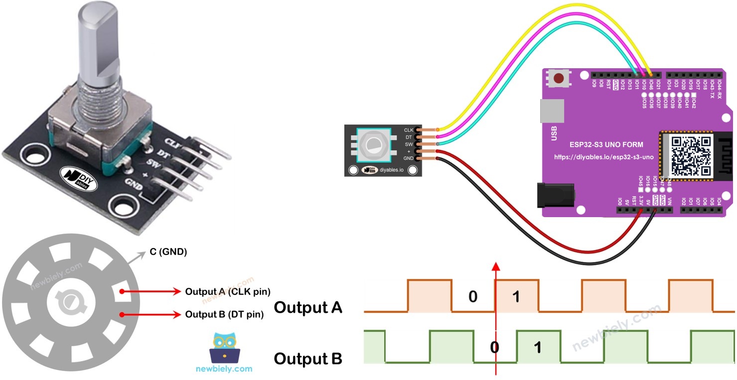
Hardware Preparation
| 1 | × | ESP32 S3 Uno-form Board | |
| 1 | × | USB Cable Type-A to Type-C (for USB-A PC) | |
| 1 | × | USB Cable Type-C to Type-C (for USB-C PC) | |
| 1 | × | Rotary Encoder | |
| 1 | × | Jumper Wires |
Or you can buy the following kits:
| 1 | × | DIYables Sensor Kit (18 sensors/displays) |
Additionally, some of these links are for products from our own brand, DIYables .
Overview of Rotary Encoder
A rotary encoder turns the rotation of a knob or shaft into electrical signals. Your code reads these signals to know how far and in which direction the knob turned.
There are two main kinds. An incremental encoder sends a pulse for every small step of rotation, so it reports changes in position. An absolute encoder gives a unique digital code for every position, so it still knows the exact angle after a power loss. This tutorial uses the incremental encoder, which is the common, low-cost module for hobby projects.
Rotary Encoder Module Pinout
Each pin of the module has one clear job. Once you know them, the wiring and the code are easy to follow.
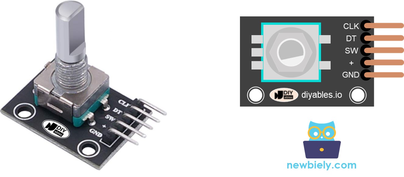
CLK pin (Output A)
This pin gives one full pulse (LOW to HIGH to LOW) for each click of the knob, in either direction. By counting these pulses, you know how far the knob turned.
DT pin (Output B)
This pin gives the same kind of pulse, but 90 degrees later than CLK. Comparing DT with CLK tells you if the knob turns clockwise or counter-clockwise.
SW pin
This pin connects to a push button inside the knob. The button is normally open. With a pull-up resistor, the pin reads HIGH when the knob is not pressed and LOW when it is pressed.
VCC pin (+)
This is the power pin. The module accepts 3.3V to 5V. With the ESP32 S3 Uno, power it from 3.3V, so the signals going into the board stay at 3.3V.
GND pin
Connect this pin to ground (0V).
Rotary Encoder vs Potentiometer
A rotary encoder looks a lot like a potentiometer, but the two parts work in very different ways. Pick the right one for your project.
An encoder can spin around without end, while a potentiometer stops after about three quarters of a turn. An encoder sends digital pulses, while a potentiometer gives an analog voltage. So an encoder is good for measuring how much the knob moved, and a potentiometer is good for knowing the exact knob position.
How Rotary Encoder Works
Inside the encoder, a slotted disc is connected to a common pin called C, which acts as ground. Two more pins, A and B, touch this disc as it turns.
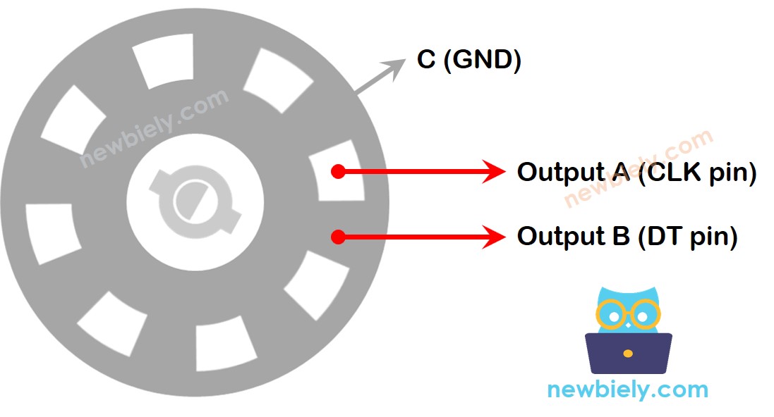
When you turn the knob, A and B touch the common pin C one after the other. The order depends on the direction. Because one pin connects a little before the other, you get two signals that are 90 degrees apart. This is called quadrature encoding.
If you turn the knob clockwise, A connects to ground before B. If you turn it counter-clockwise, B connects first. Your code watches how B behaves when A changes, and from that it finds the direction.
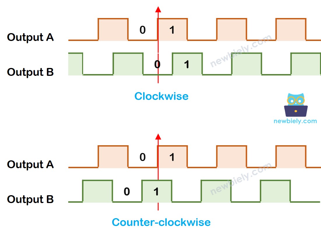
So, at the moment A goes from LOW to HIGH:
- If B is LOW, the knob turns clockwise.
- If B is HIGH, the knob turns counter-clockwise.
※ NOTE THAT:
Pins A and B are the CLK and DT pins of the module. Some makers may swap them. The code in this tutorial has been tested with the DIYables rotary encoder.
How To Program For Rotary Encoder
The program logic is short. You only need to watch one edge of the CLK signal and then look at DT.
- Read the CLK pin over and over.
- When CLK changes from LOW to HIGH, read the DT pin.
- If DT is HIGH, the knob turns counter-clockwise, so subtract 1 from the counter.
- If DT is LOW, the knob turns clockwise, so add 1 to the counter.
ESP32 S3 Uno Pinout
The image below shows the pinout of the ESP32 S3 Uno form board. Use it to find the D2, D3 and D4 header pins and their GPIO numbers before you wire the encoder.

Wiring Diagram
Connect the encoder signals to D2, D3 and D4, and power the module from the 3.3V pin.
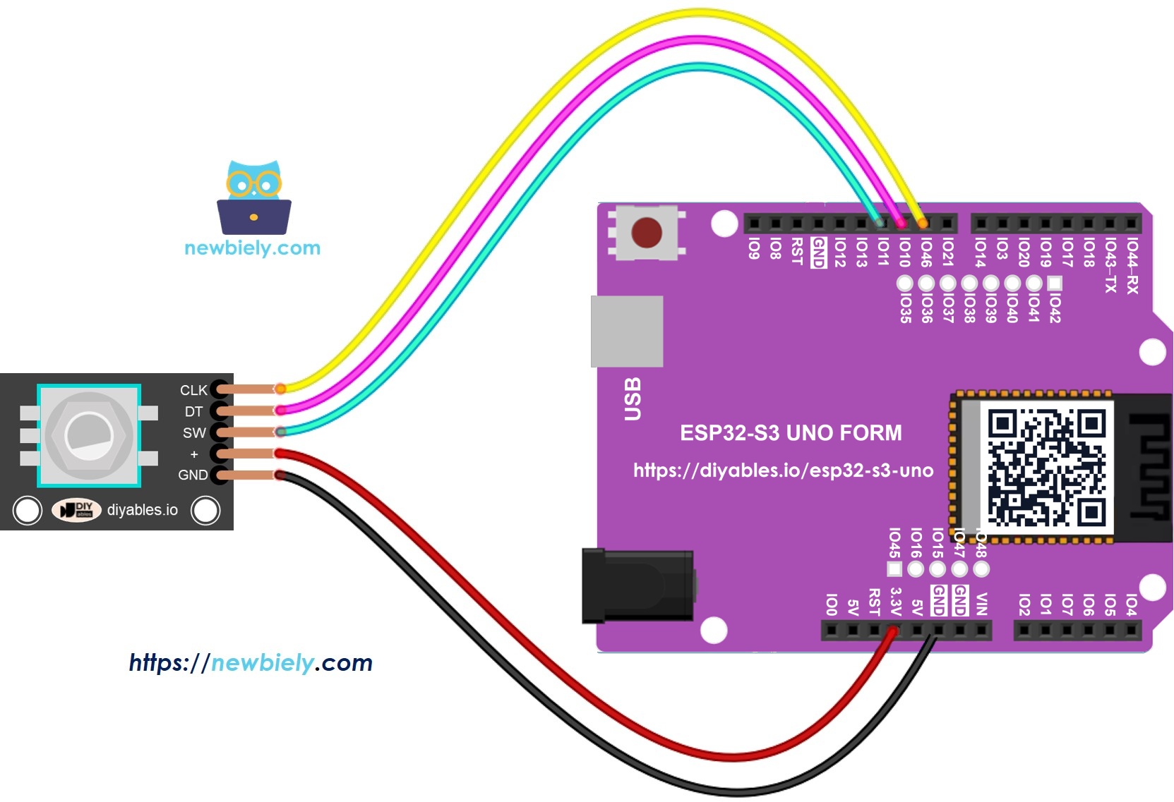
This image is created using Fritzing. Click to enlarge image
| Rotary Encoder Pin | ESP32 S3 Uno Pin |
|---|---|
| CLK | D2 (GPIO18) |
| DT | D3 (GPIO17) |
| SW | D4 (GPIO19) |
| VCC (+) | 3.3V |
| GND | GND |
WARNING
The module has pull-up resistors on its signal pins that connect to VCC. If you power it from 5V, the CLK, DT and SW pins send 5V into the board. ESP32 S3 Uno pins are NOT 5V tolerant, so always power the encoder from 3.3V.
ESP32 S3 Uno Code – Rotary Encoder without Interrupt
This first sketch uses polling: it reads the CLK pin again and again inside loop(). Each click to the right adds 1 to the counter, and each click to the left takes 1 away. It also prints a message when you press the knob.
The pins are written as GPIO numbers: 18 for D2, 17 for D3 and 19 for D4. The ezButton library handles the knob button and removes the bounce, so the button code stays short.
Detailed Instructions
- New to the ESP32 S3 Uno? Follow ESP32 S3 Uno - Getting Started first.
- Wire it up as shown in the diagram.
- Connect the board to your computer with a USB Type-C cable.
- Open Arduino IDE, choose the ESP32S3 Dev Module board and the correct COM port.
- Install the library: add the ezButton library with this guide: ezButton library.
- Copy the code above and paste it into the Arduino IDE.
- Upload the code: click the Upload button.
- Open the Serial Monitor and set it to 9600 baud.
- Test it: turn the knob clockwise, then counter-clockwise, then press the knob.
- Check the output on the Serial Monitor. It should look like the lines below.
- Tip: if clockwise turns show "Counter-clockwise", your module has CLK and DT swapped. Swap the two wires, or swap the CLK_PIN and DT_PIN numbers in the code.
Code Explanation
Every line of the sketch has a comment. Read the comments in the code to see what each line does.
ESP32 S3 Uno Code – Rotary Encoder with Interrupt
Polling works, but it has two weak points. The ESP32 S3 Uno spends its time checking the pin, and if other code in loop() runs for a long time, some clicks can be missed.
An interrupt fixes this. The board runs a small function the moment the CLK pin rises, so you do not need to check the pin all the time. Your loop() is free for other work, and the encoder is still read on time.
The sketch below uses an interrupt on the CLK pin to read the encoder.
- Copy the code above and paste it into the Arduino IDE.
- Upload the code: click the Upload button.
- Test it: turn the knob and press it. The Serial Monitor shows the same kind of output as the first sketch.
The interrupt function has the IRAM_ATTR mark. On the ESP32 S3 Uno, this keeps the function in fast internal RAM, so it runs quickly and safely when the interrupt fires.
※ NOTE THAT:
- On the ESP32 S3 Uno, every GPIO can be used as an interrupt pin. This sketch keeps CLK on D2 (GPIO18), the same position as on the wiring diagram.
- Some guides use two interrupts for one encoder. You do not need that. One interrupt on CLK is enough.
- Declare every global variable that the interrupt changes as volatile.
- Keep the interrupt function short. Do not call Serial.print() or Serial.println() inside it.
Video Tutorial
Watch the video below to see this ESP32 S3 Uno project step by step.
Function References
FAQ
Can I power the rotary encoder from 5V on the ESP32 S3 Uno?
It is not safe. The module pulls its CLK, DT and SW lines up to VCC, so with 5V power these pins send 5V into the board. ESP32 S3 Uno pins are 3.3V only. Power the encoder from the 3.3V pin, and it works just as well.
Which ESP32 S3 Uno pins can I use for the encoder interrupt?
Any GPIO can trigger an interrupt on the ESP32 S3 Uno, so you are not limited to D2 and D3 like on some Arduino boards. This tutorial uses D2 (GPIO18) for CLK. Avoid D0/D1 (USB serial) and the boot strapping pins D6 (GPIO3) and D9 (GPIO46).
Why does the counter jump by 2 or skip clicks?
This is usually contact bounce or slow polling. The interrupt sketch ignores pulses that come less than 50 ms apart, which removes most bounce. If clicks are still lost, use the interrupt sketch and keep other code in loop() short.
Is the ESP32 S3 Uno code different from the UNO R4 code?
The logic is the same. The pin numbers change to GPIO numbers (18, 17 and 19 instead of 2, 3 and 4), and the interrupt function gets the IRAM_ATTR mark. The ezButton library works the same on both boards.
How do I reset the counter when I press the knob?
Inside the if (button.isPressed()) block, set counter = 0;. In the interrupt sketch, also set prev_counter = 0; so the new value prints correctly.
What if my project needs more pins than the Uno headers give?
The ESP32 S3 Uno has two extra rows of holes with more GPIOs. GPIO15 and GPIO16 support I/O, PWM and analog. GPIO45 and GPIO35 to GPIO42 support I/O and PWM. GPIO47 and GPIO48 are output only, with PWM. Solder pin headers to use them and write the GPIO number in code. For a second encoder, GPIO35 to GPIO42 are good choices, because they work as inputs and can trigger interrupts. Do not use GPIO47/GPIO48 for an encoder, because they are output only. Two warnings: (1) GPIO47 and GPIO48 may run at 1.8V instead of 3.3V on some modules (especially ones with "V" in the name, like R8V or R16V), so 3.3V devices can be damaged or act strangely. (2) GPIO0, GPIO3 (D6), GPIO45 and GPIO46 (D9) are boot strapping pins, so a wrong connection can stop the board from booting or uploading code. Use the other extra pins first.
Troubleshooting
| Problem | Possible Cause | Solution |
|---|---|---|
| No COM port appears in Arduino IDE | USB driver missing or board not in upload mode | Install the CP210x or CH340 driver, use a data USB cable, or hold BOOT while pressing RESET |
| Nothing prints when you turn the knob | Loose wire or no power to the module | Check VCC to 3.3V, GND to GND, CLK to D2 (GPIO18) and DT to D3 (GPIO17) |
| Direction is reversed | CLK and DT are swapped on your module | Swap the CLK and DT wires, or swap the CLK_PIN and DT_PIN numbers in the code |
| Counter changes by more than 1 per click | Contact bounce or missed edges | Use the interrupt sketch, which has a 50 ms debounce |
| Button press is not detected | SW wire loose or wrong pin in code | Check SW goes to D4 (GPIO19) and the code uses 19 |
| Compile error ezButton.h not found | Library not installed | Install the ezButton library from the Library Manager |
| Serial Monitor shows strange characters | Baud rate mismatch | Set the Serial Monitor to 9600 baud |
| Board resets or acts strangely | Module powered from 5V | Power the encoder from 3.3V, since the board pins are not 5V tolerant |