
ESP32 S3 UNO - LM35 Temperature Sensor
This ESP32 S3 Uno LM35 temperature sensor tutorial shows you how to wire an LM35 to the ESP32 S3 Uno form board and measure temperature with Arduino code. The LM35 sensor is a simple analog temperature sensor, so you only need one analog pin. You will see the temperature in Celsius and Fahrenheit on the Serial Monitor.
In this tutorial, you will:
- Wire the LM35 temperature sensor to an analog pin of the ESP32 S3 Uno.
- Read the sensor voltage with analogRead() in the Arduino IDE.
- Convert the reading to degrees Celsius and Fahrenheit.
- Check the results on the Serial Monitor.
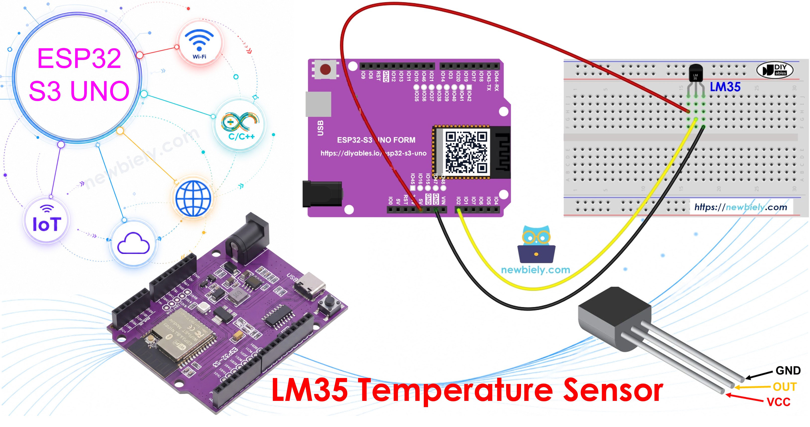
Hardware Preparation
| 1 | × | ESP32 S3 Uno-form Board | |
| 1 | × | USB Cable Type-A to Type-C (for USB-A PC) | |
| 1 | × | USB Cable Type-C to Type-C (for USB-C PC) | |
| 1 | × | LM35 Temperature Sensor | |
| 1 | × | Breadboard | |
| 1 | × | Jumper Wires |
Or you can buy the following kits:
| 1 | × | DIYables Sensor Kit (18 sensors/displays) |
Additionally, some of these links are for products from our own brand, DIYables .
Overview of LM35 Temperature Sensor
The LM35 is one of the easiest temperature sensors to start with. It needs no library and no special bus. It simply turns the temperature into a voltage that the ESP32 S3 Uno can measure.
Pinout
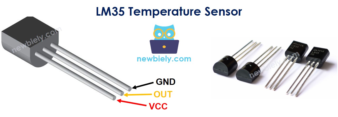
The LM35 has three pins. Each one has a simple job.
| Pin | What it does |
|---|---|
| GND | Ground. Connect it to GND (0V). |
| VCC | Power. Connect it to 5V. The LM35 needs at least 4V to work. |
| OUT | The signal pin. Its voltage changes with the temperature. Connect it to an analog pin on the ESP32 S3 Uno. |
How It Works
The output voltage of the LM35 rises in a straight line with the temperature. Every 1°C adds 10 millivolts (mV) to the OUT pin. So at 25°C the output is 250 mV.
To get the temperature, you just divide the voltage in millivolts by 10. Even at the top of its range (150°C), the output is only 1.5V. This is well below 3.3V, so the OUT pin is safe for the ESP32 S3 Uno analog input, even when the sensor runs from 5V.
ESP32 S3 Uno Pinout
The image below shows the pinout of the ESP32 S3 Uno form board. Use it to find the A0, 5V and GND header pins and their GPIO numbers before you wire the sensor.

Wiring Diagram
The LM35 needs only three wires. Follow the diagram and the table below.
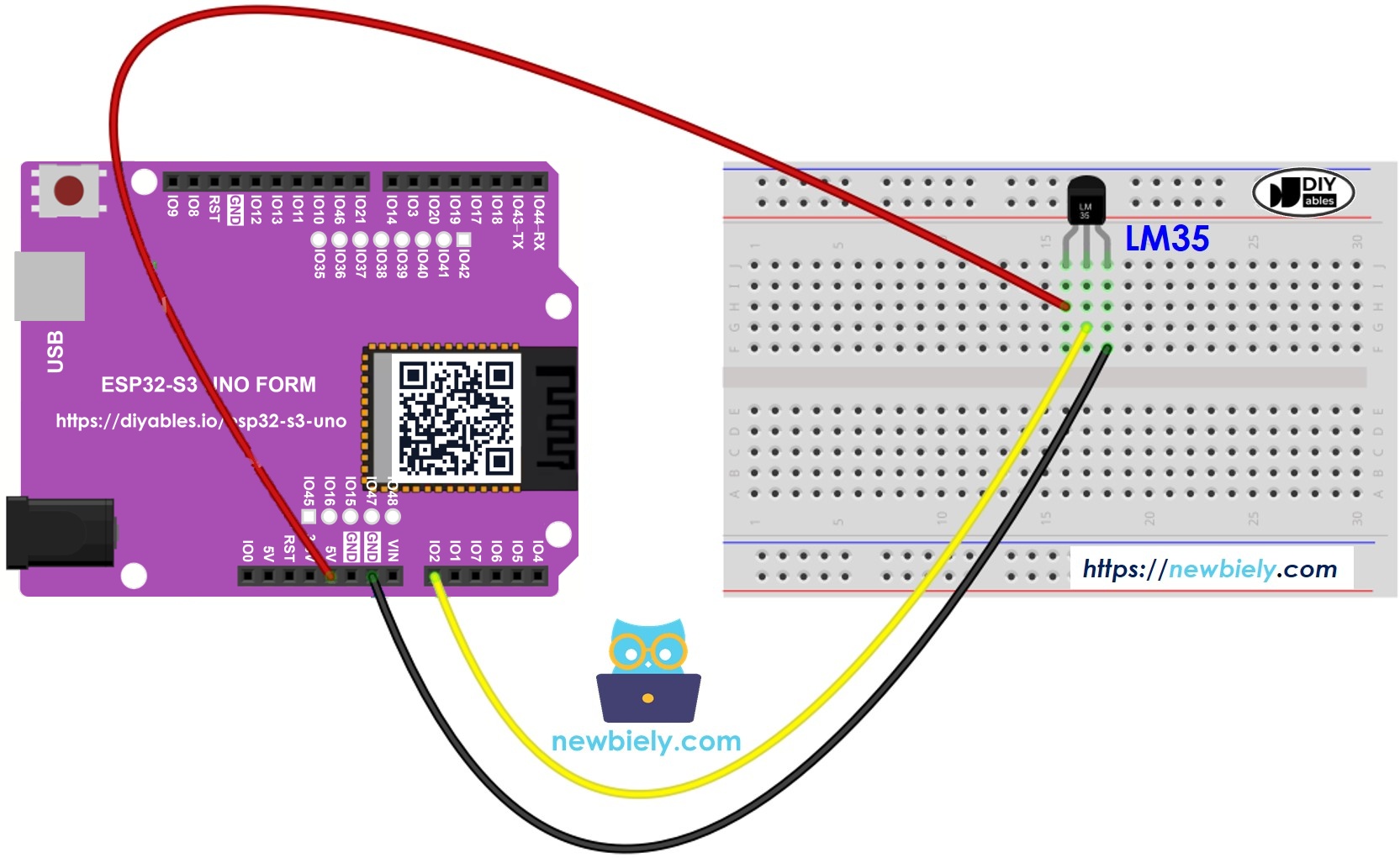
This image is created using Fritzing. Click to enlarge image
| LM35 Pin | ESP32 S3 Uno Pin |
|---|---|
| VCC | 5V |
| GND | GND |
| OUT | A0 (GPIO2) |
※ NOTE THAT:
The ESP32 S3 Uno pins are NOT 5V tolerant. Here it is safe to power the LM35 from 5V, because its OUT pin never goes above 1.5V. Never connect the 5V pin itself to A0.
How To Program For LM35 Temperature Sensor
Reading the LM35 takes four small steps. Each step is one line of code, so the full sketch is easy to follow later.
- Read the ADC value from the sensor with the analogRead() function. On the ESP32 S3 Uno the value goes from 0 to 4095.
- Turn the ADC value into a voltage in millivolts. Here ADC_VREF_mV is 3300.0 and ADC_RESOLUTION is 4096.0.
- Turn the voltage into degrees Celsius.
- Convert Celsius to Fahrenheit if you need it.
ESP32 S3 Uno Code
The sketch below reads the LM35 on A0 (GPIO2) once per second. It turns the reading into a temperature and prints it in both Celsius and Fahrenheit.
The code calls analogSetAttenuation(ADC_11db) in setup(). By default, the ESP32 S3 Uno ADC can only measure a small voltage. The 11 dB attenuation lets the analog pin read the full range, from 0V up to about 3.3V. Without it, readings hit 4095 too early and the values look wrong.
Detailed Instructions
Follow these steps one by one:
- New to the ESP32 S3 Uno? Follow ESP32 S3 Uno - Getting Started first.
- Wire it up as shown in the diagram.
- Connect the board to your computer with a USB Type-C cable.
- Open Arduino IDE, choose the ESP32S3 Dev Module board and the correct COM port.
- Copy the code above and paste it into the Arduino IDE.
- Upload the code by clicking the Upload button.
- Warm the sensor by holding it between your fingers.
- Open the Serial Monitor at 9600 baud and watch the temperature go up.
- Tip: let go of the sensor and the temperature will slowly drop back to room level.
Video Tutorial
Watch the video below to see this ESP32 S3 Uno project step by step.
Function References
These pages explain the functions used in this sketch in more detail.
FAQ
Can I power the LM35 from 3.3V on the ESP32 S3 Uno?
No, not reliably. The LM35 needs at least 4V on its VCC pin. Power it from the 5V pin. The OUT pin stays under 1.5V, so it is still safe for the 3.3V analog input.
Why does the code use 3300 and 4096 instead of 5000 and 1024?
The ESP32 S3 Uno works at 3.3V and has a 12-bit ADC. So the reading goes from 0 to 4095 and covers about 0V to 3.3V. The UNO R4 code used 5V and a 10-bit ADC (0 to 1023), which would give wrong temperatures on this board.
Why does the code call analogSetAttenuation(ADC_11db)?
It sets the ESP32 S3 Uno ADC input range to about 0V to 3.3V, so the full sensor signal maps to 0 to 4095. Without it, the range is smaller and the readings saturate early. The UNO R4 does not need this line, because it is for ESP32 boards only. Keep the sensor output at 3.3V or less.
Why is my LM35 reading a few degrees off?
The ESP32 S3 Uno ADC is not perfectly linear, and it is less accurate near 0V. Small offsets of 1 to 3°C are normal. You can add a fixed correction in code, or use analogReadMilliVolts(PIN_LM35) to get a factory-calibrated voltage in millivolts.
Can I use another analog pin instead of A0?
Yes. A1 (GPIO1), A2 (GPIO7) and A3 (GPIO6) also work. Change PIN_LM35 to the GPIO number, not the A label. Avoid D6 (GPIO3), because it is a boot strapping pin.
What if my project needs more pins than the Uno headers give?
The ESP32 S3 Uno has two extra rows of holes with more GPIOs. GPIO15 and GPIO16 support I/O, PWM and analog. GPIO45 and GPIO35 to GPIO42 support I/O and PWM. GPIO47 and GPIO48 are output only with PWM. Solder pin headers to use them and write the GPIO number in code. For extra LM35 sensors, use GPIO15 or GPIO16, since they can read analog values. Be careful with two things. First, GPIO47 and GPIO48 may run at 1.8V instead of 3.3V on some modules (especially ones with "V" in the name, like R8V or R16V), so 3.3V devices can be damaged or act strangely. Second, GPIO0, GPIO3 (D6), GPIO45 and GPIO46 (D9) are boot strapping pins, and a wrong connection can stop the board from booting or uploading code. Use the other extra pins first.
Troubleshooting
| Problem | Possible Cause | Solution |
|---|---|---|
| No COM port in Arduino IDE | USB driver missing or board not in upload mode | Install the CP210x or CH340 driver, use a data USB cable, or hold BOOT while you press RESET |
| Temperature reads 0 or does not change | OUT wire not on A0 (GPIO2) or a loose wire | Check that OUT goes to A0 and that VCC and GND are firm on the breadboard |
| Temperature is far too high or the sensor gets hot | VCC and GND are swapped | Unplug at once, check the flat side of the LM35 against the pinout, then wire again |
| Temperature is wrong or jumps a lot | Sensor powered from 3.3V | Power the LM35 from the 5V pin since it needs at least 4V |
| Readings are a few degrees off | ADC offset of the ESP32 S3 Uno | Add a small correction in code or use analogReadMilliVolts() |
| Values look too high and stuck near the top | Missing analogSetAttenuation(ADC_11db) or old 5V/1024 constants | Use the ESP32 S3 Uno code above with 3300.0 and 4096.0 |
| Strange symbols in the Serial Monitor | Wrong baud rate | Set the Serial Monitor to 9600 baud |