
ESP32 S3 UNO - SW520D Tilt Sensor
This ESP32 S3 Uno SW520D tilt sensor tutorial shows you how to wire the sensor to the ESP32 S3 Uno form board and detect tilt with simple Arduino code. The SW520D is a ball switch, also called an angle sensor module. Your sketch prints a message in the Serial Monitor each time the module tilts or comes back upright.
In this tutorial, you will:
- Wire a SW520D ball switch tilt sensor to the ESP32 S3 Uno
- Read the tilt state with digitalRead() in Arduino IDE
- Detect the moment a tilt starts and ends
- Print the tilt events to the Serial Monitor
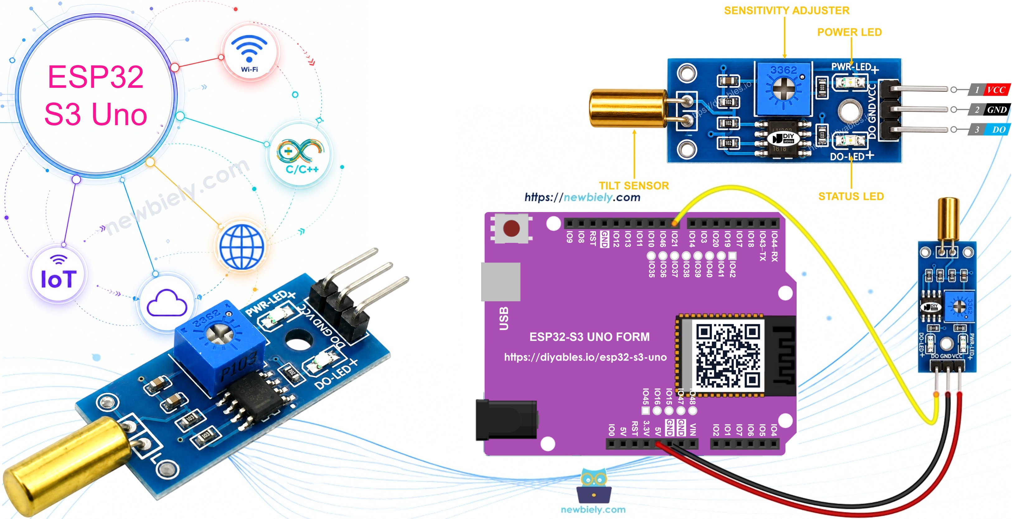
Once it works, you can change the code to turn on an LED, switch a lamp through a relay, or move a servo motor when a tilt happens.
Hardware Preparation
| 1 | × | ESP32 S3 Uno-form Board | |
| 1 | × | USB Cable Type-A to Type-C (for USB-A PC) | |
| 1 | × | USB Cable Type-C to Type-C (for USB-C PC) | |
| 1 | × | SW520D Tilt Sensor Module | |
| 1 | × | Jumper Wires |
Or you can buy the following kits:
| 1 | × | DIYables Sensor Kit (18 sensors/displays) |
Additionally, some of these links are for products from our own brand, DIYables .
Overview of SW520D Tilt Sensor
The SW520D module tells you when something leans over. It is often called a ball switch tilt sensor module or an angle sensor module. A tiny metal ball rolls inside the sensor. Depending on the angle, the ball either touches two contacts or moves away from them.
Because of this, the module gives only two states: ON or OFF. That makes it a very easy digital input for the ESP32 S3 Uno. You do not need any library to read it.
The SW520D Tilt Sensor Pinout
The module has three pins. Knowing what each one does makes the wiring quick and safe.
| Pin | What it does |
|---|---|
| VCC | Power input, 3.3V to 5V. Use 3.3V with the ESP32 S3 Uno |
| GND | Ground (0V) |
| DO | Digital output. HIGH when upright, LOW when tilted. Goes to an ESP32 S3 Uno input pin |
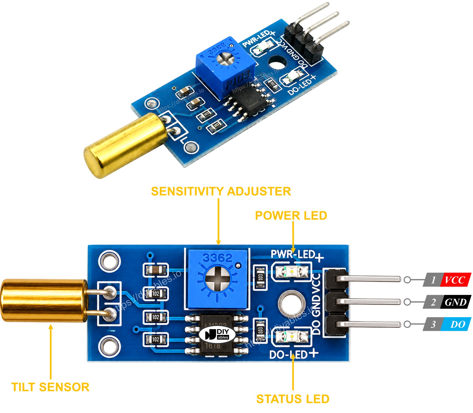
There are also two small LEDs on the board. The power LED lights up when the module gets power. The tilt LED is on while the sensor stands upright, and it turns off when the sensor tilts.
How It Works
The behavior is simple, and the code builds directly on it.
Upright
The metal ball rests on the contacts and closes the switch. The DO pin outputs HIGH.
Tilted
The ball rolls away and the switch opens. The DO pin outputs LOW.
ESP32 S3 Uno Pinout
The image below shows the pinout diagram of the ESP32 S3 Uno form board. Use it to find the Uno header pins (D2, A0, SDA…) and their GPIO numbers when you wire this tilt sensor circuit.

Wiring Diagram
Only three wires are needed. Connect the sensor output to pin D8 of the ESP32 S3 Uno, which is GPIO21 in code.
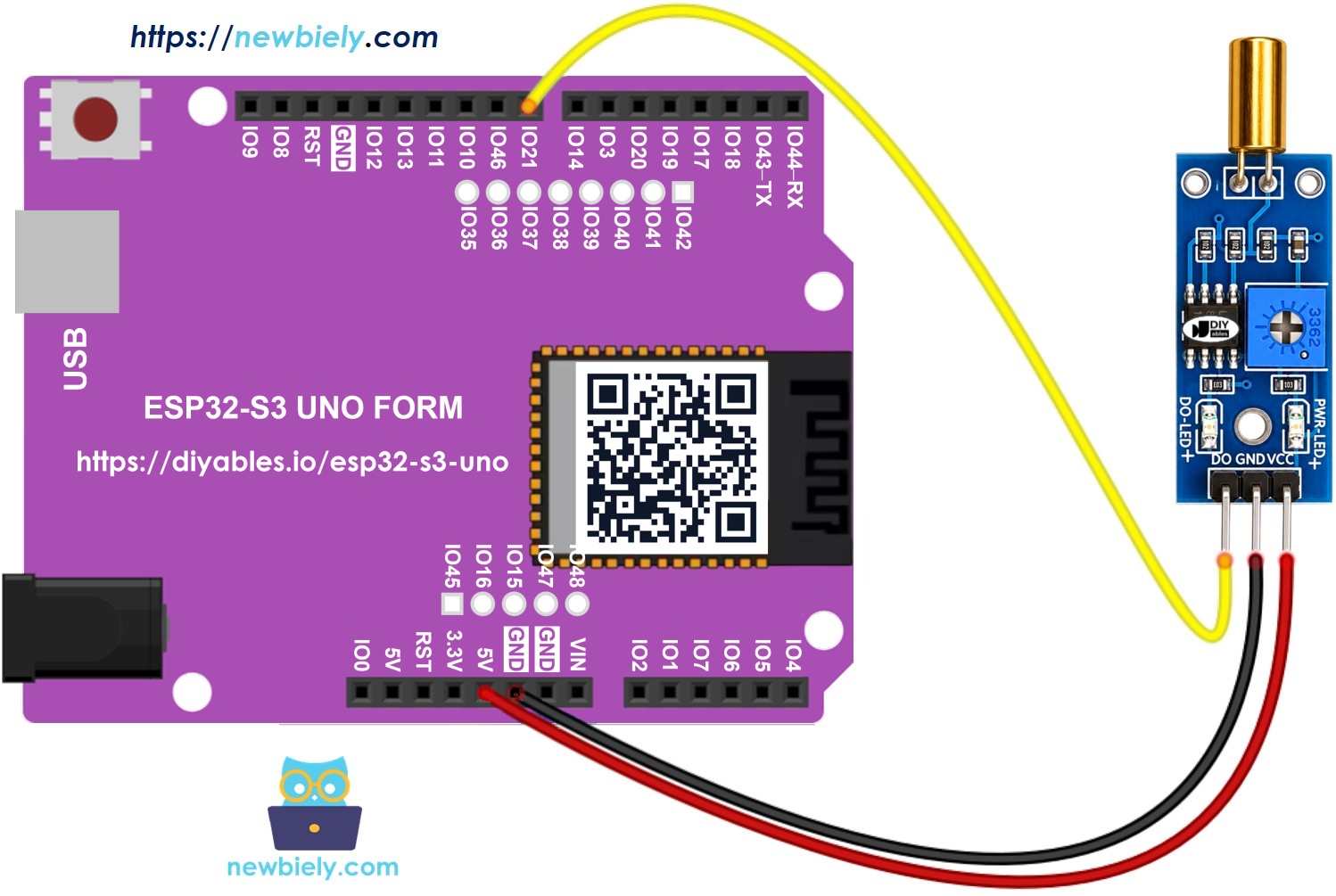
This image is created using Fritzing. Click to enlarge image
| SW520D Tilt Sensor Pin | ESP32 S3 Uno Pin |
|---|---|
| VCC | 3.3V |
| GND | GND |
| DO | D8 (GPIO21) |
WARNING
The ESP32 S3 Uno pins are NOT 5V tolerant. Power the SW520D module from 3.3V, so the DO pin also outputs 3.3V. If you power the module from 5V, its DO signal will be 5V, and you must add a voltage divider or a level shifter before pin D8.
How To Program For SW520D Tilt Sensor
Reading the sensor takes only two functions. You set the pin as an input once, and then you read it as often as you like.
- Set the ESP32 S3 Uno pin as a digital input with pinMode(). Pin D8 is GPIO21, so you write 21 in code:
- Read the current state of the pin with digitalRead():
ESP32 S3 Uno Code - Detecting the tilt
This sketch reads the sensor again and again, and compares each reading with the one before. When the state goes from HIGH to LOW, it prints that a tilt was detected. When it goes from LOW back to HIGH, it prints that the tilt has disappeared, so you only get one message per change.
Detailed Instructions
Follow these steps in order:
- New to the ESP32 S3 Uno? Follow ESP32 S3 Uno - Getting Started first.
- Wire it up as shown in the diagram.
- Connect the board to your computer with a USB Type-C cable.
- Open Arduino IDE, choose the ESP32S3 Dev Module board and the correct COM port.
- Copy the code above and paste it into Arduino IDE.
- Upload the sketch by clicking the Upload button.
- Open the Serial Monitor and set the baud rate to 9600.
- Tilt the sensor back and forth and watch the messages appear.
- Tip: If you get many messages from one small movement, the ball is bouncing. Add a short delay(50) in the loop or use debounce code, like you would for a button.
Tips for Reliable Tilt Detection
A ball switch is a simple mechanical part, so a few small details decide whether it works well. Check these points if the readings look odd.
Check the mounting angle
The SW520D only works as expected in the right position. Mount it upright, so it reads HIGH at rest and LOW when it leans.
Reduce vibration
Shaking and small bumps can move the ball and cause false messages. Fix the module to a firm surface to keep it steady.
Check the wiring
Make sure VCC, GND and DO go to 3.3V, GND and D8 (GPIO21) on the ESP32 S3 Uno.
Check the power
A stable power supply gives stable readings. A loose USB cable or a weak supply can cause random changes.
Video Tutorial
Watch the video below to see this ESP32 S3 Uno project step by step.
Function References
FAQ
Can I power the SW520D tilt sensor from 5V on the ESP32 S3 Uno?
The module works from 3.3V to 5V, but the ESP32 S3 Uno input pins accept only 3.3V. With 5V power, the DO pin outputs 5V, which can damage the board over time. Power the module from the 3.3V pin to stay safe.
Which ESP32 S3 Uno pin should I use for the tilt sensor?
This tutorial uses D8, which is GPIO21 in code. Any normal digital pin works, such as D2 (GPIO18), D4 (GPIO19) or D7 (GPIO14). Avoid D0 and D1 (USB serial), and avoid D6 and D9 because they are boot strapping pins.
Why does the code use 21 instead of 8?
On the ESP32 S3 Uno, the label on the header is not the GPIO number. The D8 header is connected to GPIO21, and Arduino code always uses the GPIO number. Check the pinout image above when you move a wire.
Can the SW520D measure the exact tilt angle?
No. The SW520D is a simple on/off switch. It only tells you if the sensor is tilted past its trigger angle or not. To measure the real angle, use an accelerometer such as the MPU6050.
Is the code different from the UNO R4 version?
The logic is the same, and no library is needed on either board. The only change is the pin number: D8 on the UNO R4 is GPIO21 on the ESP32 S3 Uno. You also select the ESP32S3 Dev Module board in Arduino IDE.
What if my project needs more pins than the Uno headers give?
The ESP32 S3 Uno has two extra rows of holes with more GPIOs. GPIO15 and GPIO16 support I/O, PWM and analog. GPIO45 and GPIO35 to GPIO42 support I/O and PWM. GPIO47 and GPIO48 are output only with PWM. Solder pin headers to use them and write the GPIO number in code. For extra tilt sensors or other inputs, use GPIO35 to GPIO42, GPIO15 or GPIO16, never GPIO47 or GPIO48. Be careful with two things. First, GPIO47 and GPIO48 may run at 1.8V instead of 3.3V on some modules, especially ones with "V" in the name like R8V or R16V, so 3.3V devices can be damaged or act strangely. Second, GPIO0, GPIO3 (D6), GPIO45 and GPIO46 (D9) are boot strapping pins, and a wrong connection can stop the board from booting or uploading code. Use the other extra pins first.
Troubleshooting
| Problem | Possible Cause | Solution |
|---|---|---|
| No COM port appears in Arduino IDE | USB driver missing or the board is not in upload mode | Install the CP210x or CH340 driver, use a data USB cable, or hold BOOT while pressing RESET |
| Nothing prints in the Serial Monitor | Wrong baud rate or the wrong port is selected | Set the Serial Monitor to 9600 baud and pick the correct COM port |
| The state never changes | DO wire is on the wrong pin or VCC/GND are loose | Check that DO goes to D8 (GPIO21) and that VCC goes to 3.3V and GND to GND |
| Many messages from one small move | The metal ball bounces inside the switch | Add a short delay or debounce logic in the code |
| Tilt and upright messages are swapped | The sensor is mounted upside down | Mount the module upright so it reads HIGH at rest |
| Random messages with no movement | Vibration or a weak power supply | Fix the sensor to a firm surface and use a stable USB port |
| Board resets or acts strangely | The module is powered from 5V and DO sends 5V into the pin | Power the module from 3.3V or add a voltage divider on DO |