
ESP32 S3 UNO - Actuator with Feedback
This ESP32 S3 Uno feedback linear actuator tutorial shows you how to wire the actuator to the ESP32 S3 Uno form board and read where its stroke is. The built-in feedback potentiometer lets you measure the position in millimeters, so you can control the linear actuator position and stop it exactly where you want.
In the earlier lesson, you used a linear actuator without feedback. That type can only extend or retract. It cannot tell you where it is.
In this tutorial, you will:
- Learn how a feedback linear actuator works and what its five wires do
- Wire the actuator and an L298N motor driver to the ESP32 S3 Uno
- Calibrate the feedback potentiometer with analogRead()
- Convert the reading into the stroke position in millimeters
- Move the actuator to a target position with Arduino code
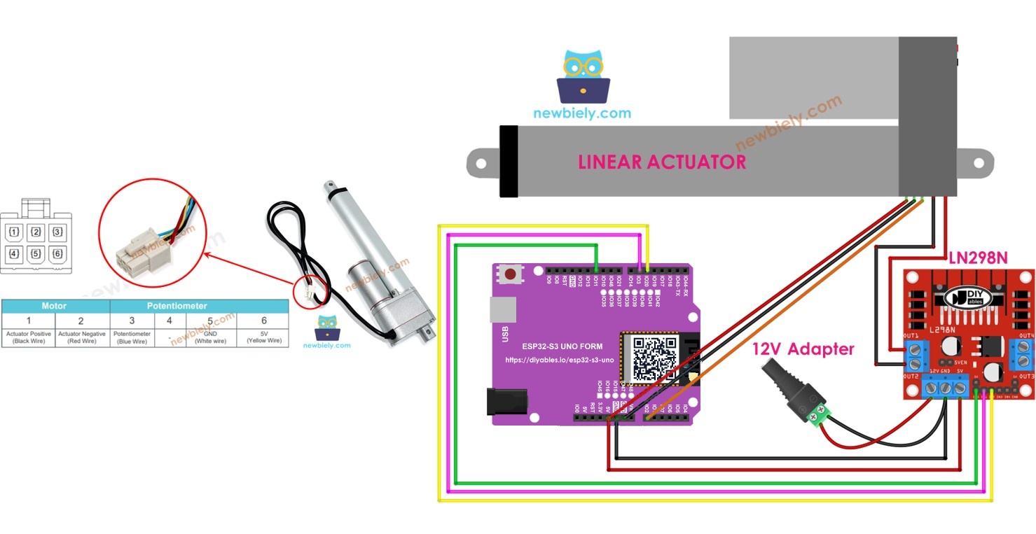
Hardware Preparation
Or you can buy the following kits:
| 1 | × | DIYables Sensor Kit (18 sensors/displays) |
Additionally, some of these links are for products from our own brand, DIYables .
Overview of Feedback Linear Actuator
A normal linear actuator moves blindly. A feedback linear actuator fixes this, because it reports its own position while it moves. That is what lets your ESP32 S3 Uno code stop it at a chosen point.
Inside the actuator there is a potentiometer that turns with the stroke. Its output voltage changes with the position, so reading this voltage tells you how far the stroke has moved.
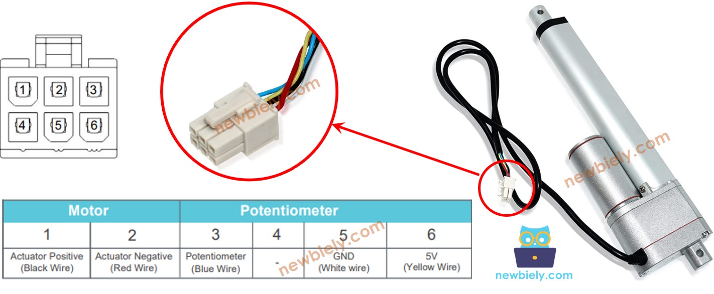
Feedback Linear Actuator Pinout
The actuator has two groups of wires. One group drives the motor, and the other group belongs to the feedback potentiometer.
Positive and negative wires
These two wires power the motor with high voltage (12V, 24V or 48V, depending on the model). Never connect them to the ESP32 S3 Uno directly. They go to the L298N driver outputs.
5V wire
This is the power wire of the feedback potentiometer. It works with 5V or 3.3V. With the ESP32 S3 Uno, connect it to 3.3V, so the feedback signal never goes above 3.3V.
GND wire
This is the ground of the feedback potentiometer. Connect it to GND.
Potentiometer wire
This is the feedback (output) wire. Its voltage changes with the stroke position. Connect it to an analog pin of the ESP32 S3 Uno.
How It Works
The motor part works like any DC linear actuator. The direction of the voltage on the two motor wires decides the direction of the stroke.
Extend
Apply the high voltage (12V, 24V, 48V…) to the positive wire and GND to the negative wire. The actuator extends at full speed until it reaches the end.
Retract
Swap the polarity: high voltage on the negative wire and GND on the positive wire. The actuator retracts at full speed until it reaches the end.
Stop
Connect both motor wires to GND (cut the power). The actuator stops right where it is, even in the middle of a move.
※ NOTE THAT:
- The motor voltage depends on your actuator model. Check its datasheet or manual for the right value.
- The actuator holds its position without power, even when it carries a load.
At the same time, the voltage on the potentiometer wire follows the stroke. When you read this voltage with the ESP32 S3 Uno, you know where the stroke is.
ESP32 S3 Uno Pinout
The image below shows the pinout diagram of the ESP32 S3 Uno form board. Use it to find the Uno header pins (D5, D6, D11, A0…) and their GPIO numbers when you wire the L298N and the actuator.

Wiring Diagram
The L298N driver sits between the ESP32 S3 Uno and the actuator motor. Before you wire it, take off all three jumpers from the L298N module.
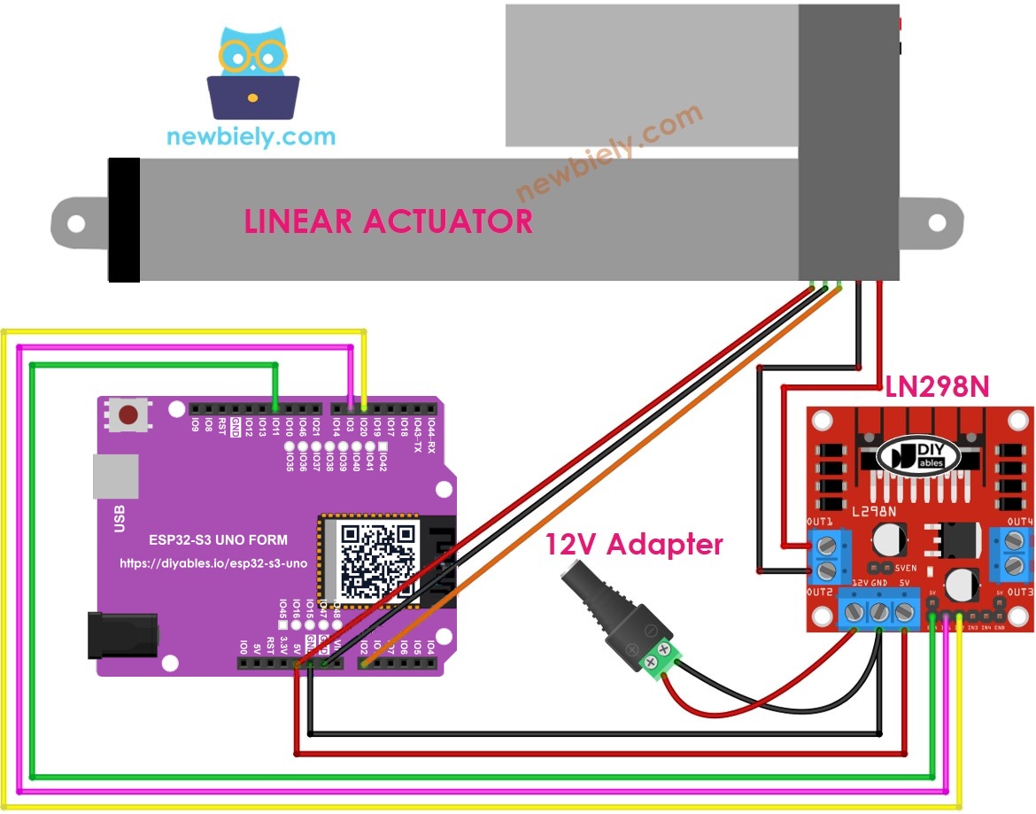
This image is created using Fritzing. Click to enlarge image
| Component Pin | ESP32 S3 Uno Pin |
|---|---|
| L298N ENA | D11 (GPIO11) |
| L298N IN1 | D6 (GPIO3) |
| L298N IN2 | D5 (GPIO20) |
| L298N GND | GND |
| Actuator potentiometer wire | A0 (GPIO2) |
| Actuator 5V wire | 3.3V |
| Actuator GND wire | GND |
The actuator's positive and negative wires go to OUT1 and OUT2 of the L298N. The 12V power adapter goes to the 12V and GND inputs of the L298N, and the L298N GND must also connect to the ESP32 S3 Uno GND.
WARNING
D6 (GPIO3) is a boot strapping pin on the ESP32 S3 Uno. The board reads it at startup to choose the boot mode. In this circuit it drives the L298N IN1 input, which is normally fine. If the board does not boot or upload code, unplug the IN1 wire, upload, and plug it back in.
WARNING
The ESP32 S3 Uno analog pins are NOT 5V tolerant. Power the actuator's feedback potentiometer from 3.3V, not 5V. With 5V, the feedback wire can reach 5V near the end of the stroke and damage the A0 (GPIO2) pin.
How to control extend/retract a linear actuator
Moving the actuator in and out is the base of everything in this lesson. If you have not tried it yet, see the ESP32 S3 Uno Actuator tutorial first.
How to find the position of the linear actuator
To turn the feedback voltage into millimeters, you need three numbers: the stroke length, the reading at full retract, and the reading at full extend. You find them once, then use them in every sketch.
Calibration
Every actuator and every board gives slightly different readings. A short calibration run tells you the real values of your own setup.
- Find the stroke length in millimeters. Measure it with a ruler or read it from the datasheet.
- Upload the calibration sketch below. It fully extends the actuator, reads the feedback, then fully retracts it and reads the feedback again.
- Open the Serial Monitor and wait. Each move takes about 20 seconds. You will see output like this:
- Write down both values. On the ESP32 S3 Uno they are in the 0 to 4095 range, because the ADC is 12-bit.
- Check the order. If the minimum and maximum values are swapped, swap IN1_PIN and IN2_PIN in the code.
- Put the three values (stroke length, max, min) into the next sketch.
The sketch calls analogSetAttenuation(ADC_11db) in setup(). By default, the ESP32 S3 Uno ADC can only measure a small voltage. The 11 dB attenuation lets A0 read the full range from 0V up to about 3.3V. Without it, the reading hits 4095 too early, and the actuator position looks wrong.
ESP32 S3 Uno code that calculate the position of the actuator
This sketch extends the actuator and prints the stroke position while it moves. It uses map() to scale the analog reading from your calibrated min and max values to 0 to the stroke length in millimeters.
- Update the three values STROKE_LENGTH, POTENTIOMETER_MAX and POTENTIOMETER_MIN with your calibration results.
- Upload the code to the ESP32 S3 Uno.
- Open the Serial Monitor and watch the position grow as the stroke extends.
How to control a linear actuator to a specific position
Now you can close the loop. This sketch reads the position all the time and compares it with a target (50 mm by default). If the stroke is too short, it extends. If it is too long, it retracts. When it is within the tolerance (5 mm), it stops.
Change targetPosition_mm to move the stroke to another spot. A smaller TOLERANCE gives a more exact stop, but if it is too small, the actuator may jump back and forth around the target.
Video Tutorial
Watch the video below to see this ESP32 S3 Uno project step by step.
Summary
You wired a feedback linear actuator and an L298N driver to the ESP32 S3 Uno. You calibrated the feedback potentiometer, turned its 12-bit reading into millimeters, and moved the stroke to an exact target. With this, you can build your own position control projects, like a smart lift, a sliding door or an adjustable stand, with the ESP32 S3 Uno.
Function References
FAQ
Can I power the actuator's feedback potentiometer from 5V on the ESP32 S3 Uno?
No. The ESP32 S3 Uno pins work at 3.3V and are not 5V tolerant. Connect the feedback 5V wire to the 3.3V pin. The potentiometer works fine at 3.3V, and the feedback signal then stays inside the safe range of A0.
Why are my calibration values near 4000 and not near 1000 like on the UNO R4?
The ESP32 S3 Uno has a 12-bit ADC, so analogRead() returns 0 to 4095. The UNO R4 code uses a 10-bit range (0 to 1023) by default. Always run the calibration sketch on your own board and use those values.
Why does the code call analogSetAttenuation(ADC_11db)?
It sets the ESP32 S3 Uno ADC input range to about 0 to 3.3V, so the full feedback signal maps to 0 to 4095. Without it the range is smaller, and readings saturate early near the end of the stroke. The UNO R4 does not need this line. It is ESP32-only. Keep the feedback voltage at 3.3V or less.
Can the ESP32 S3 Uno 3.3V pins drive the L298N inputs?
Yes. The L298N reads about 2.3V and above as HIGH, so the 3.3V signals from D5, D6 and D11 work. Just make sure the L298N GND and the ESP32 S3 Uno GND are connected.
Can I control the actuator speed?
Yes. Remove the ENA jumper (as in the wiring) and use analogWrite(ENA_PIN, value) instead of digitalWrite(ENA_PIN, HIGH). D11 (GPIO11) supports PWM on the ESP32 S3 Uno. A lower speed also helps the actuator stop closer to the target.
What if my project needs more pins than the Uno headers give?
The ESP32 S3 Uno has two extra rows of holes with more GPIOs: GPIO15 and GPIO16 (I/O, PWM, analog), GPIO45 and GPIO35 to GPIO42 (I/O, PWM), and GPIO47/GPIO48 (output only, PWM). Solder pin headers to use them and write the GPIO number in code. For a second actuator's feedback wire, use GPIO15 or GPIO16, because they have analog input. For extra L298N control lines, GPIO35 to GPIO42 are a good choice. Be careful with two things. First, GPIO47/GPIO48 may run at 1.8V instead of 3.3V on some modules (especially ones with "V" in the name, like R8V or R16V), so 3.3V devices can be damaged or act strangely. Second, GPIO0, GPIO3 (D6), GPIO45 and GPIO46 (D9) are boot strapping pins, and a wrong connection can stop the board from booting or uploading code. Use the other extra pins first.
Troubleshooting
| Problem | Possible Cause | Solution |
|---|---|---|
| No COM port in Arduino IDE | USB driver missing or board not in upload mode | Install the CP210x or CH340 driver. Hold BOOT, press RESET, then release BOOT and upload again |
| Upload fails or board does not boot | IN1 wire on D6 (GPIO3) pulls the strapping pin at startup | Unplug the IN1 wire, upload the code, then plug it back in |
| Actuator does not move | No 12V power or ENA jumper problem or GND not shared | Check the 12V adapter on the L298N, check the ENA wire to D11, and connect L298N GND to ESP32 S3 Uno GND |
| Position reading stays at 4095 | Feedback powered from 5V or attenuation not set | Power the feedback potentiometer from 3.3V and keep analogSetAttenuation(ADC_11db) in setup() |
| Position goes down when the actuator extends | Min and max values swapped | Swap IN1_PIN and IN2_PIN in the code, then run the calibration again |
| Position in mm is wrong | Old UNO R4 calibration values used | Run the calibration sketch on the ESP32 S3 Uno and update POTENTIOMETER_MAX, POTENTIOMETER_MIN and STROKE_LENGTH |
| Actuator shakes around the target | TOLERANCE too small or noisy readings | Increase TOLERANCE or average a few analogRead() values |
| Serial Monitor shows strange text | Wrong baud rate | Set the Serial Monitor to 9600 baud |