
ESP32 S3 UNO - Obstacle Avoidance Sensor
This ESP32 S3 Uno obstacle avoidance sensor tutorial shows you how to connect an infrared obstacle sensor to the ESP32 S3 Uno form board and read it with Arduino code. The IR obstacle detector tells you when something is in front of it, and the result appears on the Serial Monitor.
In this tutorial, you will:
- Learn how an IR obstacle avoidance sensor works
- Wire the infrared obstacle sensor to the ESP32 S3 Uno
- Read the sensor output with digitalRead()
- Detect the moment an obstacle appears and the moment it goes away
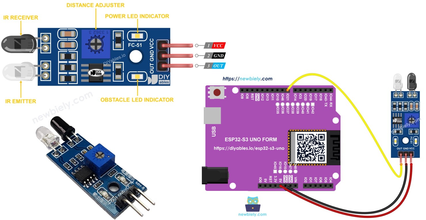
Hardware Preparation
Or you can buy the following kits:
| 1 | × | DIYables Sensor Kit (18 sensors/displays) |
Additionally, some of these links are for products from our own brand, DIYables .
Overview of IR Obstacle Avoidance Sensor
An IR obstacle avoidance sensor is a small, cheap module that tells you if an object is close to it. It is a common part in robot cars, counters and touchless switches.
The module uses infrared light to see objects. It can sense things from about 2cm to 30cm away. A small potentiometer on the board lets you set how far it looks.
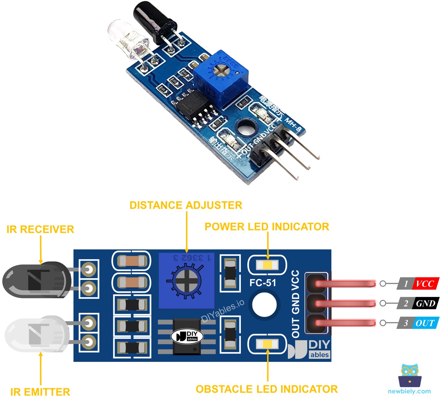
Pinout
The sensor has only three pins, so the wiring is very simple.
GND pin
Connect it to GND (0V).
VCC pin
Connect it to the power supply. The module works with 3.3V or 5V. With the ESP32 S3 Uno, use 3.3V.
OUT pin
This is the digital output. It is LOW when an obstacle is in front of the sensor, and HIGH when there is none. Connect it to a digital input pin of the ESP32 S3 Uno.
How It Works
Knowing how the sensor decides "obstacle or no obstacle" helps you read its output the right way in code.
The module has two parts: an IR transmitter and an IR receiver. The transmitter sends out infrared light. When an object is in front of the sensor, the light bounces back and the receiver picks it up. The module then shows the result on the OUT pin:
- Obstacle in front of the sensor: OUT is LOW.
- No obstacle in front of the sensor: OUT is HIGH.
Note that the logic is "active LOW". A LOW reading means something was found.
※ NOTE THAT:
The sensor can get bent during shipping, and then it may not work well. If it acts strangely, gently bend the IR transmitter and receiver so they point straight ahead and stand parallel to each other.
ESP32 S3 Uno Pinout
The image below shows the pinout of the ESP32 S3 Uno form board. Use it to find the Uno header pins (D8, GND, 3.3V…) and their GPIO numbers while you wire the sensor.

Wiring Diagram
The sensor needs just three wires: power, ground and the output signal to pin D8.
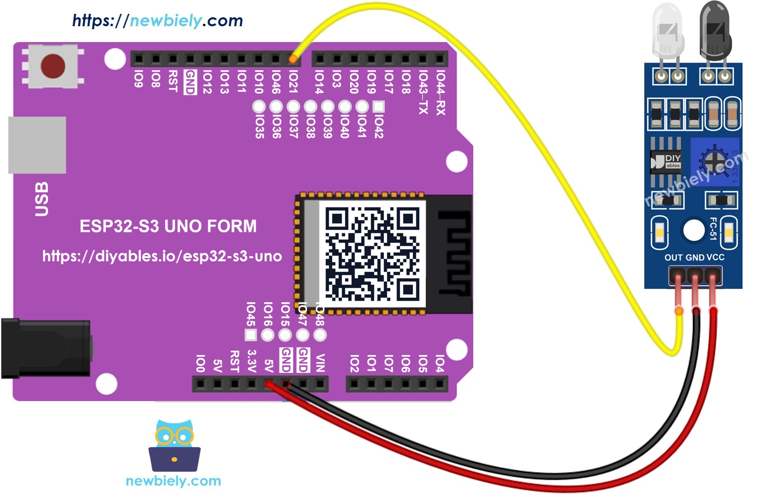
This image is created using Fritzing. Click to enlarge image
| Obstacle Sensor Pin | ESP32 S3 Uno Pin |
|---|---|
| VCC | 3.3V |
| GND | GND |
| OUT | D8 (GPIO21) |
WARNING
ESP32 S3 Uno pins work with 3.3V logic and are NOT 5V tolerant. If you power the sensor from 5V, its OUT pin can send 5V into GPIO21 and damage it. Power the sensor from 3.3V, or put a voltage divider on the OUT line if you must use 5V.
How To Program For IR Obstacle Avoidance Sensor
Reading the sensor takes only two steps, because the OUT pin is a plain digital signal.
- Set the ESP32 S3 Uno pin as a digital input with pinMode(). Here we use D8, which is GPIO21 in code.
- Read the state of that pin with digitalRead().
ESP32 S3 Uno Code
You will usually use the obstacle sensor in one of two ways:
- Act based on the current state: is an obstacle there right now or not?
- Act on a change: the moment an obstacle shows up, or the moment it goes away.
The two sketches below cover both cases.
ESP32 S3 Uno code for checking if the obstacle is present
This sketch reads the OUT pin every 100ms and prints whether an obstacle is there. Because the sensor is active LOW, a LOW reading prints "The obstacle is present".
Detailed Instructions
- New to the ESP32 S3 Uno? Follow ESP32 S3 Uno - Getting Started first.
- Wire it up as shown in the diagram.
- Connect the board to your computer with a USB Type-C cable.
- Open Arduino IDE, choose the ESP32S3 Dev Module board and the correct COM port.
- Copy the code above and paste it into the Arduino IDE.
- Upload the code by clicking the Upload button.
- Test it by holding an object in front of the sensor for a few seconds, then moving it away.
- Check the output on the Serial Monitor (baud rate 9600).
- Tip: If the sensor never sees your object, turn the potentiometer on the module slowly until its LED turns on at the distance you want.
ESP32 S3 Uno code for detecting obstacle
This sketch remembers the last reading and compares it with the new one. It prints a message only when the state changes: HIGH to LOW means an obstacle was detected, and LOW to HIGH means it was cleared.
Detailed Instructions
- Copy the code above and open it in the Arduino IDE.
- Upload the code by clicking the Upload button.
- Test it by putting an object in front of the sensor for a moment, then taking it away.
- Check the output on the Serial Monitor.
- Tip: Each event is printed only once, so this sketch is a good base for counters and alarms.
Video Tutorial
Watch the video below to see this ESP32 S3 Uno project step by step.
Function References
FAQ
Can I power the IR obstacle sensor from 5V on the ESP32 S3 Uno?
The module itself works at 5V, but its OUT pin then gives a 5V signal. ESP32 S3 Uno pins are 3.3V only and are not 5V tolerant. Power the sensor from 3.3V, or use a voltage divider on the OUT line.
Why does the sensor give LOW when an obstacle is present?
The module is designed as "active LOW". Its output stays HIGH when nothing is in front of it and goes LOW when the IR light bounces back. Your code just needs to check for LOW to know an object is there.
Why do I write 21 in the code and not 8?
On the ESP32 S3 Uno, the Uno header label D8 is connected to GPIO21 of the chip. In code you always use the GPIO number. The wiring stays on the D8 header, like on a classic Uno board.
How do I change the detection distance?
Turn the small potentiometer on the module. Turning one way makes the range longer, the other way makes it shorter. The range is about 2cm to 30cm, and dark or shiny objects may be harder to detect.
What if my project needs more pins than the Uno headers give?
The ESP32 S3 Uno has two extra rows of holes with more GPIOs: GPIO15 and GPIO16 (I/O, PWM, analog), GPIO45 and GPIO35 to GPIO42 (I/O, PWM), and GPIO47/GPIO48 (output only, PWM). Solder pin headers and write the GPIO number in code. For more obstacle sensors, GPIO35 to GPIO42, GPIO15 or GPIO16 are good choices, but not GPIO47/GPIO48 because they cannot read inputs. Be careful with two things. GPIO47 and GPIO48 may run at 1.8V instead of 3.3V on some modules (especially ones with "V" in the name, like R8V or R16V), so 3.3V devices can be damaged or act strangely. GPIO0, GPIO3 (D6), GPIO45 and GPIO46 (D9) are boot strapping pins, and a wrong connection can stop the board from booting or uploading code. Use the other extra pins first.
Can I use several obstacle sensors at the same time?
Yes. Connect each sensor's OUT pin to its own digital pin, for example D7 (GPIO14) and D8 (GPIO21), and read each one with digitalRead(). All sensors can share the same 3.3V and GND.
Troubleshooting
| Problem | Possible Cause | Solution |
|---|---|---|
| No COM port in Arduino IDE | USB driver missing or board not in upload mode | Install the CP210x or CH340 driver, use a data USB cable, or hold BOOT while pressing RESET |
| Serial Monitor shows nothing or strange characters | Wrong baud rate | Set the Serial Monitor to 9600 baud |
| Always prints "NOT present" | Range too short, or sensor not powered | Check VCC and GND wires, then turn the potentiometer to increase the range |
| Always prints "present" | Range too long, or a nearby surface reflects IR | Turn the potentiometer to reduce the range and point the sensor away from the table |
| Readings are wrong or random | OUT wire on the wrong pin, or code uses 8 instead of 21 | Wire OUT to D8 and use GPIO 21 in the code |
| Sensor works badly outdoors | Sunlight contains a lot of infrared light | Use the sensor indoors or shade it from direct sunlight |
| Detection is weak or one-sided | IR LED and receiver bent during shipping | Gently bend them so they point straight ahead and are parallel |
| Board resets or GPIO gets hot | Sensor powered from 5V sends 5V into GPIO21 | Power the sensor from 3.3V or add a voltage divider |