
ESP32 S3 UNO - Actuator
This ESP32 S3 Uno linear actuator tutorial shows you how to wire a 12V linear actuator to the ESP32 S3 Uno form board through an L298N driver and control it with Arduino code. You will make the actuator push out and pull back in, stop it at any point, and change its speed with PWM. It is a simple first step into DIY automation.
In this tutorial, you will:
- Learn what a linear actuator is and how it moves
- Wire an L298N driver and a linear actuator to the ESP32 S3 Uno
- Extend and retract the actuator with the IN1 and IN2 pins
- Stop the actuator before it reaches its end point
- Control the linear actuator speed with analogWrite()
This page covers linear actuators without feedback. If your actuator has a position feedback wire, read the ESP32 S3 Uno - Actuator with Feedback guide instead.
Hardware Preparation
Or you can buy the following kits:
| 1 | × | DIYables Sensor Kit (18 sensors/displays) |
Additionally, some of these links are for products from our own brand, DIYables .
Overview of Linear Actuator
A linear actuator turns the rotation of a small motor into a straight push or pull. You see it in electric desks, window openers and solar trackers. Knowing how it moves makes the code much easier to follow.

Linear Actuator Pinout
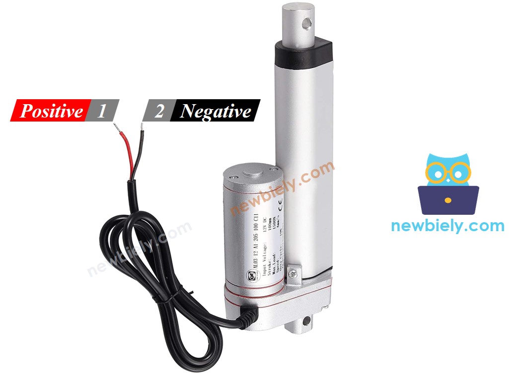
The actuator has only two wires. The positive wire is often red, and the negative wire is often black.
How It Works
Every linear actuator has a rated voltage, so check it before you buy one. This guide uses a 12V actuator as an example.
Direction
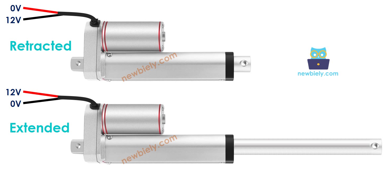
If you connect 12V to the positive wire and GND to the negative wire, the actuator pushes out at full speed until it hits its end limit. If you swap the two wires, it pulls back in at full speed until it reaches the other limit. If you connect both wires to GND, the rod stops moving.
※ NOTE THAT:
A DC motor, servo motor or stepper motor without gears cannot hold its position under load when the power is off. A linear actuator can. Its internal gears and lead screw keep the rod in place, even with no power.
Speed
If you give the actuator less than 12V, it still moves, but more slowly. Changing the supply voltage in a real circuit is hard, so this method is rarely used. Instead, you keep the voltage fixed and switch it on and off very fast with a PWM signal. A higher PWM duty cycle makes the rod move faster.
How to Control a Linear Actuator with ESP32 S3 Uno
In most projects, you want three things from the actuator. You want it to extend at full speed, retract at full speed, and, if needed, move at a slower speed.
The ESP32 S3 Uno can make the control signals, but its pins give only 3.3V and a few milliamps. That is far too weak to move an actuator. So you put a driver between the board and the actuator.
The driver does two jobs. First, it boosts the weak signal from the board so it can power the actuator. Second, it swaps the supply polarity based on a second signal from the board, and this decides whether the rod extends or retracts.
※ NOTE THAT:
This guide works for any linear actuator. The 12V model is only an example. Even with a small 5V actuator you still need a driver, because an ESP32 S3 Uno pin outputs only 3.3V and cannot supply the current an actuator needs. Never connect an actuator straight to a GPIO pin.
This guide uses the L298N driver. Other chips and modules, such as the L293D, can also drive a linear actuator.
Overview of L298N Driver
The L298N is a cheap and popular driver board. It can run linear actuators, DC motors and stepper motors. Once you know its pins, the wiring is simple.
L298N Driver Pinout
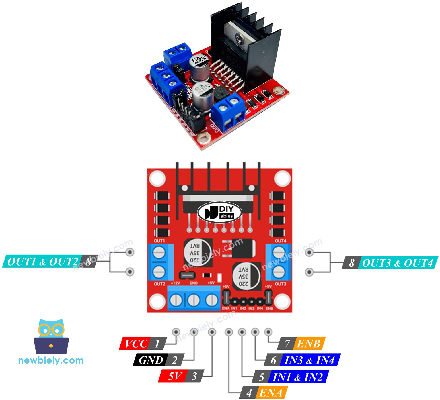
The L298N has two channels, A and B. Each channel drives one actuator, so you can move two actuators at the same time, each on its own. The module has 13 pins in total.
Common pins for both channels
The VCC pin brings power to the actuator and accepts 5V to 35V. The GND pin is the common ground and goes to 0V. The 5V pin powers the logic chip on the module, and you can feed it from the 5V pin of the ESP32 S3 Uno.
Channel A pins
The ENA pin sets the speed of actuator A. Remove its jumper and connect it to a PWM pin to change how fast the rod moves. The IN1 and IN2 pins set the direction. When one is HIGH and the other is LOW, the actuator extends or retracts. When both are HIGH or both are LOW, it stops. Actuator A connects to OUT1 and OUT2.
Channel B pins
Channel B works the same way. ENB sets the speed of actuator B when you remove its jumper and give it a PWM signal. IN3 and IN4 set the direction: one HIGH and one LOW makes the rod move, and equal levels make it stop. Actuator B connects to OUT3 and OUT4.
Power inputs and jumpers
The L298N has two power inputs. The VCC and GND pins power the actuator, from 5V to 35V. The 5V and GND pins power the module itself, from 5V to 7V. The module also has three jumpers for special uses. To keep things simple, remove all of them.
With one ESP32 S3 Uno and one L298N, you can control two linear actuators at once. Each actuator needs only three pins on the board.
※ NOTE THAT:
This tutorial controls one actuator on channel A. A second actuator on channel B works in the same way.
ESP32 S3 Uno Pinout
The image below shows the pinout diagram of the ESP32 S3 Uno form board. Use it to find the Uno header pins (D6, D7, D13, 5V…) and their GPIO numbers when you wire the L298N driver.

How To Control Linear Actuator
Now you connect everything and learn the few lines of code that move the rod. Each part below shows one small action you can reuse in your own projects.
Wiring Diagram
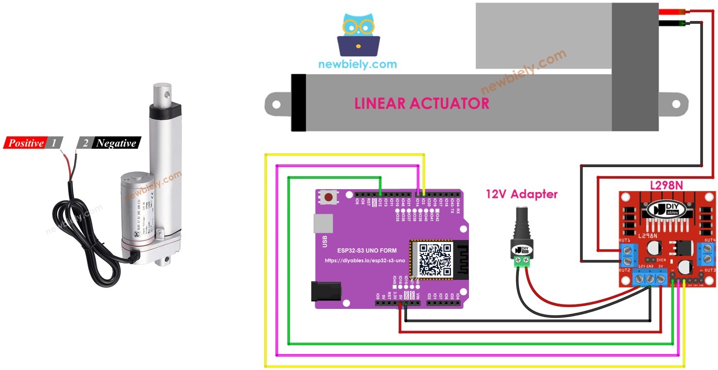
Remove all three jumpers from the L298N module before you start. Then wire the board, the driver and the actuator as shown below.
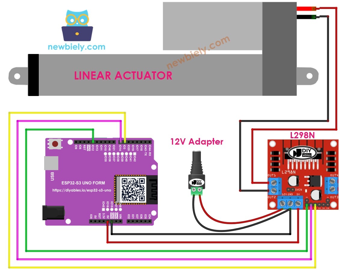
This image is created using Fritzing. Click to enlarge image
| L298N Pin | ESP32 S3 Uno Pin |
|---|---|
| ENA | D13 (GPIO12) |
| IN1 | D7 (GPIO14) |
| IN2 | D6 (GPIO3) |
| 5V | 5V |
| GND | GND |
Connect the actuator wires to OUT1 and OUT2. Connect the positive wire of the 12V power adapter to the VCC pin of the L298N, and its negative wire to the GND pin of the L298N.
WARNING
D6 (GPIO3) is a boot strapping pin on the ESP32 S3 Uno. The chip reads it at power-up to choose its boot mode. The L298N input normally does not disturb it, but if the board does not boot or cannot upload code, unplug the IN2 wire, upload the code, and then plug it back in.
※ NOTE THAT:
The ESP32 S3 Uno sends 3.3V signals to the ENA, IN1 and IN2 pins. The L298N reads 3.3V as HIGH, so no level shifter is needed. All signals go OUT of the board, so no 5V ever reaches an ESP32 S3 Uno pin.
How To Make Linear Actuator Expand/Retract
The direction comes from the levels you write to IN1 and IN2. The table below shows every combination for channel A.
| IN1 pin | IN2 pin | Direction |
|---|---|---|
| LOW | LOW | Linear Actuator A stops |
| HIGH | HIGH | Linear Actuator A stops |
| HIGH | LOW | Linear Actuator A extends |
| LOW | HIGH | Linear Actuator A retracts |
Extend the actuator
Retract the actuator
※ NOTE THAT:
If the rod moves the wrong way, the actuator wires on OUT1 and OUT2 are swapped. You can swap the two wires, or you can swap the IN1 and IN2 levels in the code.
How To Stop Linear Actuator from Extending or Retracting
The actuator stops by itself when it reaches its fully extended or fully retracted point. You can also stop it earlier, anywhere along its stroke. There are two ways to do this.
Set the speed to zero
Set IN1 and IN2 to the same level
Both LOW:
Or both HIGH:
How To Control the Speed of Linear Actuator via L298N Driver
To change the speed, you send a PWM signal to the ENA pin instead of a fixed HIGH. The L298N amplifies this signal and drives the actuator with it.
- Connect an ESP32 S3 Uno pin (here D13) to the ENA pin of the L298N.
- Call analogWrite() on that pin to send the PWM signal.
The speed value goes from 0 to 255. A value of 0 stops the actuator, and 255 moves it at full speed. On the ESP32 S3 Uno, analogWrite() uses the same 0 to 255 range as on other Arduino boards.
ESP32 S3 Uno Example Code
This sketch is a simple full-speed test. It pushes the rod all the way out, holds it there, pulls it all the way back in, holds it again, and repeats.
The ENA pin is set HIGH once in setup(), so the actuator always runs at full speed. Each move lasts 20 seconds, which is long enough for most actuators to reach their limit and stop on their own. The pin numbers in the code are GPIO numbers: 12 for D13, 14 for D7 and 3 for D6.
Detailed Instructions
- New to the ESP32 S3 Uno? Follow ESP32 S3 Uno - Getting Started first.
- Remove all three jumpers from the L298N module.
- Wire it up as shown in the diagram.
- Connect the board to your computer with a USB Type-C cable.
- Open Arduino IDE, choose the ESP32S3 Dev Module board and the correct COM port.
- Copy the code above and paste it into Arduino IDE.
- Upload the code by clicking the Upload button.
- Plug in the 12V adapter and watch the actuator. The rod extends and stops at its limit, holds its position for a while, retracts and stops at its other limit, then holds again. This cycle repeats forever.
- Tip: if your actuator is slow and does not reach its limit in 20 seconds, make the delay() values larger. You can find the full-stroke time in the actuator's datasheet.
Video Tutorial
Watch the video below to see this ESP32 S3 Uno project step by step.
Summary
In this ESP32 S3 Uno tutorial, you drove a linear actuator through an L298N driver. You wired the driver, made the rod extend and retract with two direction pins, stopped it in two ways, and set its speed with a PWM signal on the ENA pin. These skills work for any actuator without feedback. You can now use them to build your own DIY automation projects, such as a motorized lid, a lifting platform or a window opener.
FAQ
Can I connect a linear actuator directly to an ESP32 S3 Uno pin?
No. An ESP32 S3 Uno pin gives only 3.3V and a few milliamps, while an actuator needs much more current, often 1A or more. The motor inside can also send voltage spikes back into the pin and damage the board. Always use a driver such as the L298N.
Does the L298N work with the 3.3V signals of the ESP32 S3 Uno?
Yes. The L298N logic inputs see about 2.3V or more as HIGH, so a 3.3V signal is enough for ENA, IN1 and IN2. You do not need a level shifter, because the signals only go from the board to the driver.
Can I power the actuator from the 5V pin of the ESP32 S3 Uno?
No. A 12V actuator needs its own 12V supply. Even a 5V actuator draws too much current for the board or the USB port, and it can reset the board. Use a separate adapter for the actuator and connect its ground to the board ground through the L298N GND pin.
Does the actuator keep its position when the power is off?
Yes. The gears and lead screw inside a linear actuator lock the rod in place. That is why you can stop it halfway and it will hold a load without any power, unlike a DC motor without gears.
Can I use other pins instead of D13, D7 and D6?
Yes. Almost every ESP32 S3 Uno pin can output PWM, so ENA, IN1 and IN2 can go to other free pins. Just change the GPIO numbers in the code. Pins like D4 (GPIO19), D5 (GPIO20) or D8 (GPIO21) are good choices because they are not boot strapping pins.
What if my project needs more pins than the Uno headers give, for example for a second actuator?
The ESP32 S3 Uno has two extra rows of holes with more GPIOs. GPIO15 and GPIO16 offer I/O, PWM and analog. GPIO45 and GPIO35 to GPIO42 offer I/O and PWM. GPIO47 and GPIO48 are output only, with PWM. Solder pin headers to use them and write the GPIO number in code. For a second actuator, GPIO35 to GPIO42 work well for ENB, IN3 and IN4. Be careful with two things. First, GPIO47 and GPIO48 may run at 1.8V instead of 3.3V on some modules (especially ones with "V" in the name, like R8V or R16V), so 3.3V devices can be damaged or act strangely. Second, GPIO0, GPIO3 (D6), GPIO45 and GPIO46 (D9) are boot strapping pins, and a wrong connection can stop the board from booting or uploading code. Use the other extra pins first.
Troubleshooting
| Problem | Possible Cause | Solution |
|---|---|---|
| No COM port or upload fails | USB driver missing or board not in download mode | Install the CP210x or CH340 driver. Or hold BOOT, press RESET, then release BOOT and upload again |
| Board does not boot or upload with the driver wired | IN2 on D6 (GPIO3) is pulled at power-up | Unplug the IN2 wire, upload, then plug it back in |
| Actuator does not move at all | Jumpers still on the L298N or no 12V power | Remove all three jumpers and check that the 12V adapter is plugged into VCC and GND of the L298N |
| Actuator moves only one way | IN1 or IN2 wire is loose or on the wrong pin | Check that IN1 goes to D7 and IN2 goes to D6 and that the code uses GPIO14 and GPIO3 |
| Actuator moves the wrong way | Actuator wires on OUT1 and OUT2 are swapped | Swap the two actuator wires or swap the IN1 and IN2 levels in the code |
| Actuator is very slow or weak | Supply voltage too low or adapter too weak | Use a 12V adapter that can give the rated current of the actuator |
| Board resets when the actuator starts | No common ground or poor power wiring | Connect the adapter GND, L298N GND and board GND together, and never power the actuator from the board |
| Rod does not reach the end before it turns back | The delay is shorter than the full-stroke time | Increase the delay() values in the code |