
ESP32 S3 UNO - Button - Servo Motor
This ESP32 S3 Uno button servo motor tutorial shows you how to wire a push button and a servo motor to the ESP32 S3 Uno form board and control the servo with Arduino code. Each press of the button moves the servo to 90 degrees, and the next press moves it back to 0 degrees. You will write the button control servo motor code twice: once in the simple way, and once with debouncing so every press is read correctly.
In this tutorial, you will:
- Wire a button and a servo motor to the ESP32 S3 Uno
- Detect a button press with digitalRead() and INPUT_PULLUP
- Rotate a servo motor with the ESP32Servo library
- Add button debouncing with the ezButton library
Hardware Preparation
Or you can buy the following kits:
| 1 | × | DIYables Sensor Kit (18 sensors/displays) |
Additionally, some of these links are for products from our own brand, DIYables .
Buy Note: For controlling multiple servo motors, use the PCA9685 16 Channel PWM Servo Driver Module to save MCU pins and simplify wiring.
ESP32 S3 Uno Pinout
The image below shows the pinout diagram of the ESP32 S3 Uno form board. Use it to find the Uno header pins (D7, D9, 5V…) and their GPIO numbers when you wire the button and the servo.

Wiring Diagram
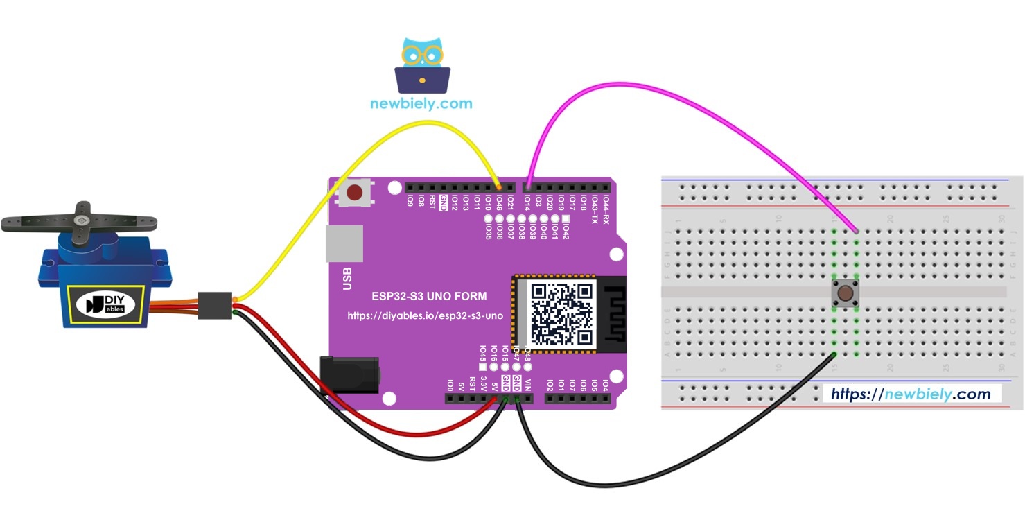
Connect the button to D7 and GND, and the servo signal wire to D9, as shown below. The servo takes its power from the 5V pin.
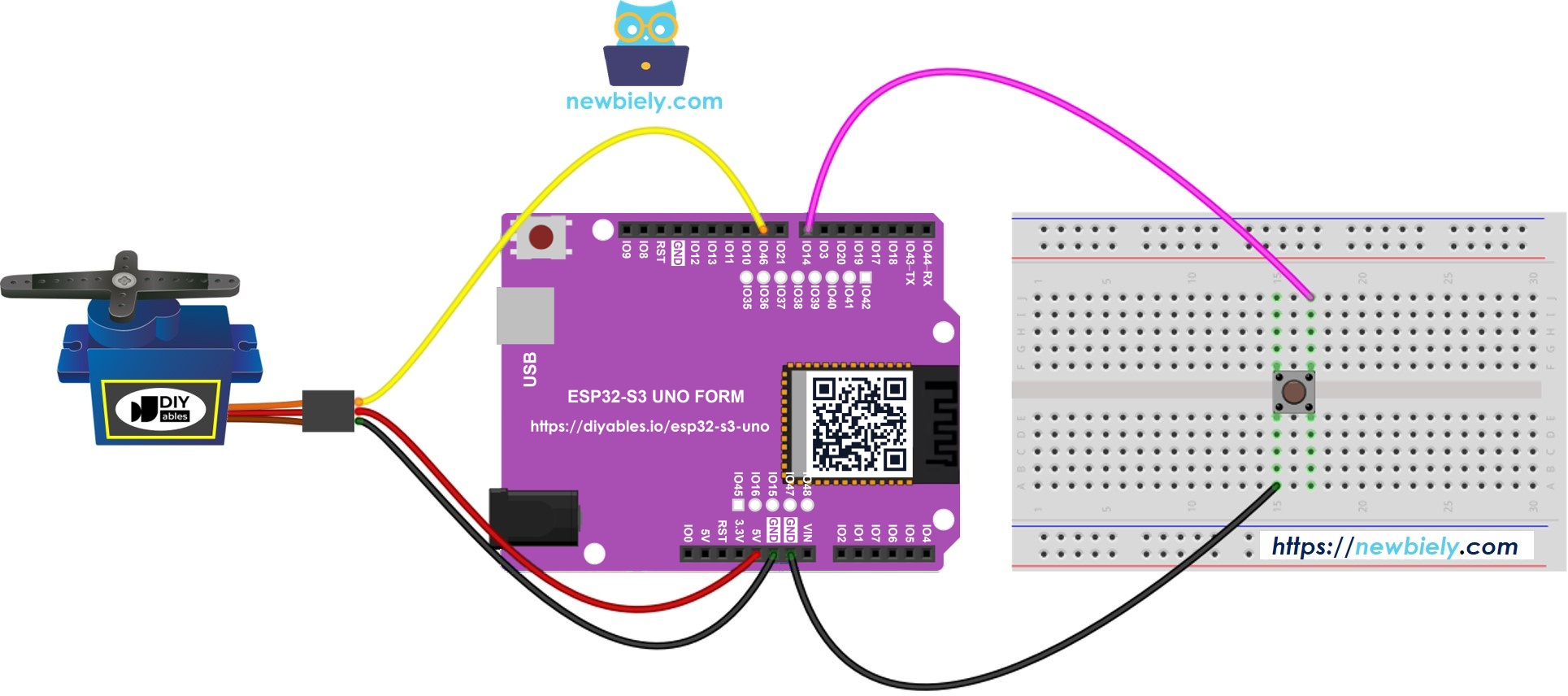
This image is created using Fritzing. Click to enlarge image
| Component Pin | ESP32 S3 Uno Pin |
|---|---|
| Button pin 1 | D7 (GPIO14) |
| Button pin 2 | GND |
| Servo VCC (red) | 5V |
| Servo GND (brown or black) | GND |
| Servo Signal (orange or yellow) | D9 (GPIO46) |
WARNING
D9 is GPIO46, a boot strapping pin on the ESP32 S3 Uno. The board reads this pin at power-up to pick its boot mode. A servo signal wire is normally safe here, but if the board does not boot or cannot upload code, unplug the servo signal wire from D9, upload, and then plug it back in.
※ NOTE THAT:
The servo runs from 5V, but the ESP32 S3 Uno only sends a 3.3V control signal to it. This is fine, because the signal goes OUT of the board. Most hobby servos read a 3.3V signal without problems. The button is wired to GND, so no 5V ever reaches an ESP32 S3 Uno pin.
Video Tutorial
Watch the video below to see this ESP32 S3 Uno project step by step.
FAQ
Can the ESP32 S3 Uno power a servo motor directly?
A small servo like the SG90 can run from the 5V pin when the board is powered by USB. Bigger servos draw more current and can make the board reset. For those, use an external 5V supply and connect its GND to the ESP32 S3 Uno GND.
Why does the code use ESP32Servo.h instead of Servo.h?
The standard Servo library only supports AVR and some other Arduino boards, not the ESP32 S3 Uno. The ESP32Servo library by Kevin Harrington uses the PWM hardware of the board but keeps the same functions. Your UNO R4 servo code works after you change only the include line and the pin numbers.
Does the servo work with the 3.3V signal from the ESP32 S3 Uno?
Yes, most hobby servos accept a 3.3V control signal. The servo still gets 5V for power on its red wire. Only the signal wire goes to the GPIO pin, and that signal goes out of the board, so no level shifter is needed.
Why do I need debouncing for the button?
The metal contacts in a button bounce for a short time when you press it. The board is fast enough to see these bounces as many presses. Without debouncing, the servo can move twice or stay in the same place after one press.
Can I use a different pin for the servo instead of D9?
The wiring diagram uses D9 (GPIO46), which is a boot strapping pin. It works in most cases, but if you have boot or upload problems, you can move the signal wire to another PWM pin such as D5 (GPIO20). Then change SERVO_PIN in the code to 20.
What if my project needs more pins than the Uno headers give?
The ESP32 S3 Uno has two extra rows of holes with more GPIOs: GPIO15 and GPIO16 (I/O, PWM, analog), GPIO45 and GPIO35 to GPIO42 (I/O, PWM), and GPIO47/GPIO48 (output only, PWM). Solder pin headers to use them and write the GPIO number in code. For extra buttons, use GPIO35 to GPIO42, not GPIO47/GPIO48, because those two are output only. For extra servos, GPIO15, GPIO16 or GPIO35 to GPIO42 work well. Be careful with two things. First, GPIO47/GPIO48 may run at 1.8V instead of 3.3V on some modules (especially ones with "V" in the name, like R8V or R16V), so 3.3V devices can be damaged or act strangely. Second, GPIO0, GPIO3 (D6), GPIO45 and GPIO46 (D9) are boot strapping pins, and a wrong connection can stop the board from booting or uploading code. Use the other extra pins first.
Troubleshooting
| Problem | Possible Cause | Solution |
|---|---|---|
| No COM port shows up in Arduino IDE | USB driver missing or board not in upload mode | Install the CP210x or CH340 driver. Or hold BOOT, press RESET, then release BOOT and upload again |
| Upload fails or board does not boot | The servo signal on D9 (GPIO46) affects the boot strapping pin | Unplug the servo signal wire from D9 during upload, then plug it back in |
| Compile error "Servo.h - No such file" | The code uses the AVR Servo library | Install the ESP32Servo library and use #include |
| Compile error about ezButton.h | The ezButton library is not installed | Install ezButton from the Library Manager |
| Servo does not move at all | Wrong wiring or no power to the servo | Check that red goes to 5V, brown to GND and the signal wire to D9 |
| Servo jitters or the board resets | The servo draws too much current from USB | Power the servo from an external 5V supply and join the GNDs |
| One press moves the servo twice | Button contact bounce | Use the debouncing code with the ezButton library |
| Button press is never detected | Button not wired to GND or wrong pin | Wire one button leg to D7 (GPIO14) and the other leg to GND |