
ESP32 S3 UNO - GPS
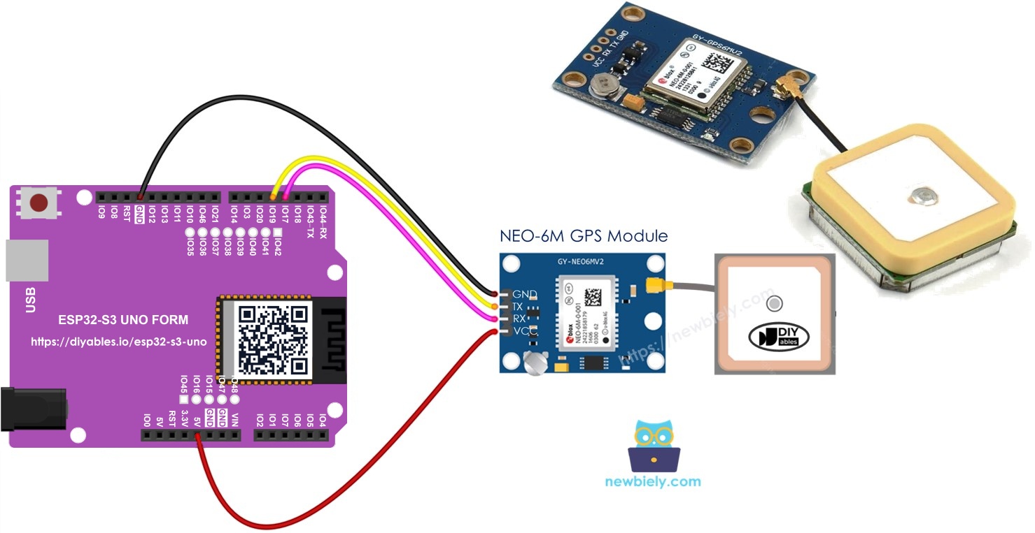
This ESP32 S3 Uno GPS tutorial shows you how to connect a NEO-6M GPS module to the ESP32 S3 Uno form board and read your location with Arduino code. You will get the GPS coordinates (latitude, longitude and altitude), the speed in km/h, and the current date and time. You will also learn how to measure the distance from where you are to a fixed place, such as London.
In this tutorial, you will:
- Learn the pinout of the NEO-6M GPS module.
- Wire the GPS module to the ESP32 S3 Uno using a hardware serial port.
- Install the TinyGPSPlus library in the Arduino IDE.
- Read GPS coordinates, speed, date and time on the Serial Monitor.
- Calculate the distance between two GPS locations.
Hardware Preparation
| 1 | × | ESP32 S3 Uno-form Board | |
| 1 | × | USB Cable Type-A to Type-C (for USB-A PC) | |
| 1 | × | USB Cable Type-C to Type-C (for USB-C PC) | |
| 1 | × | NEO-6M GPS module | |
| 1 | × | Jumper Wires |
Or you can buy the following kits:
| 1 | × | DIYables Sensor Kit (18 sensors/displays) |
Additionally, some of these links are for products from our own brand, DIYables .
Overview of NEO-6M GPS module
The NEO-6M is a small, low-cost GPS receiver. It listens to satellites and sends your position and time as plain text (NMEA sentences) over a serial line. A library turns that text into numbers you can use, so your code stays short.
The module needs a clear view of the sky to get a fix. Indoors, it may take many minutes or never find the satellites at all.
Pinout
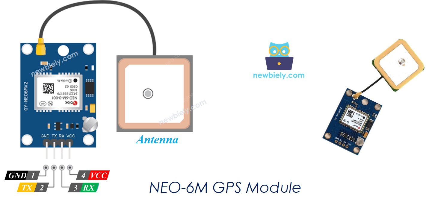
The NEO-6M GPS module has only four pins, so the wiring is quick. Two pins give power and two pins carry the serial data.
VCC pin
Connect this pin to the power supply. Most NEO-6M boards have their own regulator, so you can feed them 5V (or 3.3V on many modules).
GND pin
Connect this pin to GND (0V).
TX pin
The module sends GPS data out on this pin. Connect it to an RX pin of the ESP32 S3 Uno.
RX pin
The module receives commands on this pin. Connect it to a TX pin of the ESP32 S3 Uno.
ESP32 S3 Uno Pinout
The image below shows the pinout of the ESP32 S3 Uno form board. Use it to find the Uno header pins (D3, D4…) and their GPIO numbers while you wire the GPS module.

Wiring Diagram
The GPS module talks to the board through a serial line, so its TX goes to the board's RX and its RX goes to the board's TX. The ESP32 S3 Uno can put a hardware UART on almost any pin, so D4 and D3 work well here.
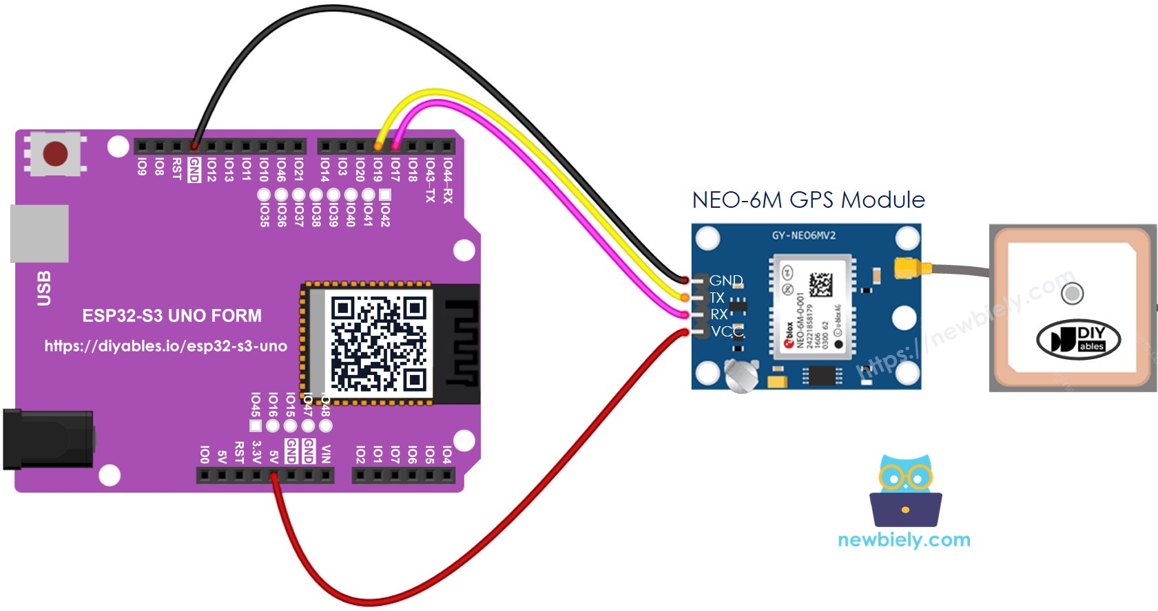
This image is created using Fritzing. Click to enlarge image
| GPS Module Pin | ESP32 S3 Uno Pin |
|---|---|
| VCC | 5V |
| GND | GND |
| TX | D4 (GPIO19) |
| RX | D3 (GPIO17) |
ESP32 S3 Uno Code
Many GPS examples use SoftwareSerial, but that library does not exist on the ESP32 S3 Uno. Instead, the code uses the built-in hardware serial port UART1 and maps it to GPIO19 (RX) and GPIO17 (TX). This is more reliable than a software serial port.
Reading GPS coordinates, speed (km/h), and date time
This sketch reads the text from the GPS module and feeds it to TinyGPSPlus one character at a time. Each time a full sentence arrives, it prints the latitude, longitude, altitude, speed, date and time. If no data comes in after 5 seconds, it prints a message that tells you to check the wiring.
Detailed Instructions
Follow these steps in order:
- New to the ESP32 S3 Uno? Follow ESP32 S3 Uno - Getting Started first.
- Wire it up as shown in the diagram.
- Connect the board to your computer with a USB Type-C cable.
- Open Arduino IDE, choose the ESP32S3 Dev Module board and the correct COM port.
- Open the Library Manager by clicking the Libraries icon on the left side of the Arduino IDE.
- Search for the library: type TinyGPSPlus in the search box and find TinyGPSPlus by Mikal Hart.
- Install it by clicking the Install button.
- Search for TinyGPSPlus created by Mikal Hart and click the Install button.
- Copy the code above and paste it into the Arduino IDE.
- Upload the code by clicking the Upload button.
- Place the GPS antenna near a window or outside, then open the Serial Monitor at 9600 baud.
- Tip: the first fix after power-up (cold start) can take a few minutes. Until then, you will see INVALID values.
Calculating the distance from current location to a predefined location
This sketch works out how far you are from London (latitude: 51.508131, longitude: -0.128002). It uses the distanceBetween() function of TinyGPSPlus, which returns meters, and divides the result by 1000 to show kilometers.
Detailed Instructions
- Copy the code above and paste it into the Arduino IDE.
- Upload the code to the ESP32 S3 Uno by clicking the Upload button.
- Open the Serial Monitor at 9600 baud and look at the result.
- Tip: change LONDON_LAT and LONDON_LON to the coordinates of your home or school to measure the distance to that place.
Video Tutorial
Watch the video below to see this ESP32 S3 Uno project step by step.
FAQ
Can I use SoftwareSerial with the ESP32 S3 Uno?
No. The SoftwareSerial library from the UNO R4 does not work on the ESP32 S3 Uno. Use a hardware serial port instead, such as HardwareSerial(1) with gpsSerial.begin(9600, SERIAL_8N1, RX_PIN, TX_PIN). You can choose the RX and TX GPIOs yourself.
Why does the Serial Monitor show INVALID for the location?
The GPS module has not found enough satellites yet. Take it outside or put it next to a window, and wait a few minutes. When the small LED on the module starts to blink, it has a fix.
Why do I see only two decimals in the latitude and longitude?
Serial.println() prints a double with two decimals by default. Use Serial.println(gps.location.lat(), 6) to print six decimals, which gives a position accurate to about 10 cm in the number (the real GPS accuracy is a few meters).
Is the GPS time my local time?
No. The GPS module gives UTC time. Add or subtract your time zone offset in the code to get your local time.
What if my project needs more pins than the Uno headers give?
The ESP32 S3 Uno has two extra rows of holes with more GPIOs: GPIO15 and GPIO16 (I/O, PWM, analog), GPIO45 and GPIO35 to GPIO42 (I/O, PWM), and GPIO47/GPIO48 (output only, PWM). Solder pin headers to use them and write the GPIO number in code. For a GPS project, GPIO35 to GPIO42 are good for extra serial devices or buttons, and GPIO15/16 fit analog sensors. Do not use GPIO47/GPIO48 for inputs. Be careful with two things. First, GPIO47/GPIO48 may run at 1.8V instead of 3.3V on some modules (especially ones with "V" in the name, like R8V or R16V), so 3.3V devices can be damaged or act strangely. Second, GPIO0, GPIO3 (D6), GPIO45 and GPIO46 (D9) are boot strapping pins, and a wrong connection can stop the board from booting or uploading code. Use the other extra pins first.
Troubleshooting
| Problem | Possible Cause | Solution |
|---|---|---|
| No COM port in the Arduino IDE | USB driver missing or charge-only cable | Install the CP210x or CH340 driver, use a data USB cable, or hold BOOT while you press RESET |
| "No GPS data received - check wiring" message | TX and RX are swapped or a wire is loose | Connect GPS TX to D4 (GPIO19) and GPS RX to D3 (GPIO17), and check VCC and GND |
| Location stays INVALID for a long time | No clear view of the sky | Move the module outside or near a window and wait a few minutes for the first fix |
| Strange characters instead of GPS data | Wrong baud rate | Keep gpsSerial at 9600 and set the Serial Monitor to 9600 baud |
| Compile error about TinyGPS++.h | Library not installed | Install TinyGPSPlus by Mikal Hart from the Library Manager |
| Compile error about SoftwareSerial.h | Using code made for other boards | Use the ESP32 S3 Uno code above, which uses HardwareSerial |
| Board resets or GPS LED is off | Weak power supply | Power the module from the 5V pin and use a good USB cable |