
ESP32 S3 UNO - Button - LED

This ESP32 S3 Uno button LED tutorial shows you how to control an LED with a push button on the ESP32 S3 Uno form board. You will build two small projects: one where the LED follows the button, and one where each press toggles the LED on or off. You will also see why button debounce matters and how the ezButton library fixes it.

In this tutorial, you will:

  1. Wire a push button and an LED to the ESP32 S3 Uno
  2. Turn the LED on only while the button is pressed
  3. Toggle the LED with each button press
  4. Learn why a button needs debouncing
  5. Use the ezButton library to make the button toggle LED reliable
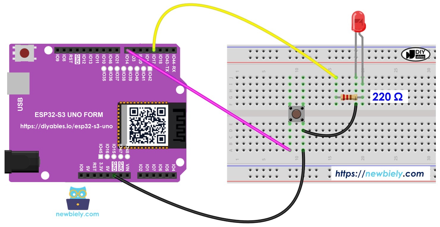
ESP32 S3 Uno button LED

Hardware Preparation

1×ESP32 S3 Uno-form Board
1×USB Cable Type-A to Type-C (for USB-A PC)
1×USB Cable Type-C to Type-C (for USB-C PC)
1×Breadboard-mount Button with Cap
1×Breadboard-mount Button Kit
1×Panel-mount Push Button
1×Push Button Module
1×LED Kit
1×LED (red)
1×LED Module
1×Alternatively, Button and LED Kit
1×220Ω Resistor
1×Breadboard
1×Jumper Wires

Or you can buy the following kits:

1×DIYables Sensor Kit (18 sensors/displays)
Disclosure: Some of the links provided in this section are Amazon affiliate links. We may receive a commission for any purchases made through these links at no additional cost to you.
Additionally, some of these links are for products from our own brand, DIYables .

Buy Note: Use the LED Module for easier wiring. It includes an integrated resistor.

Overview of LED and Button

This project joins two basic parts: a button as the input and an LED as the output. If you have not used them before, it helps to learn each one alone first. The tutorials below explain the pinout, how each part works, and how to program it.

Two ways to control the LED

In the first project, the LED simply copies the button. The ESP32 S3 Uno turns the LED on while you hold the button down, and turns it off when you let go.

In the second project, the LED changes state each time you press the button. When the ESP32 S3 Uno sees the button go from HIGH to LOW (a new press), it switches the LED: off becomes on, and on becomes off. Releasing the button does nothing. This second project needs debouncing to work well, and you will see the difference with and without it.

ESP32 S3 Uno Pinout

The image below shows the pinout of the ESP32 S3 Uno form board. Use it to match the Uno header pins (D3, D7…) to their GPIO numbers when you build the circuit.

ESP32 S3 Uno pinout diagram

Wiring Diagram

The button goes to pin D7 and the LED goes to pin D3 through a 220 ohm resistor. Both parts share the GND pin.
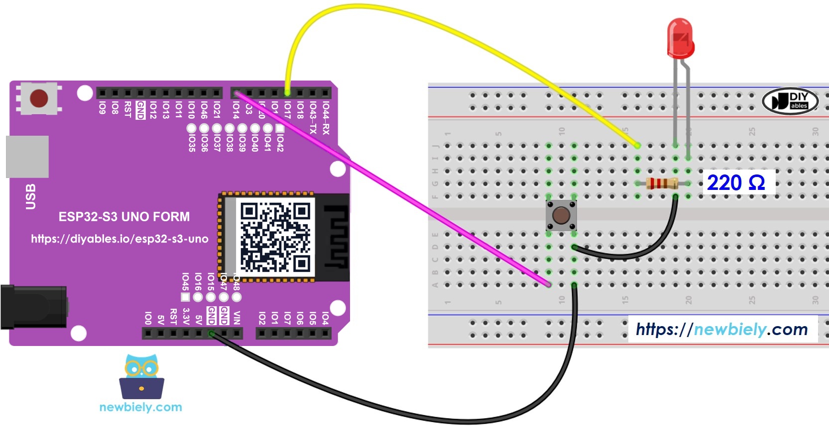
The wiring diagram between ESP32 S3 Uno Button LED

This image is created using Fritzing. Click to enlarge image

Component Pin ESP32 S3 Uno Pin
Button pin 1 D7 (GPIO14)
Button pin 2 GND
LED Anode (+) via 220 ohm resistor D3 (GPIO17)
LED Cathode (-) GND

※ NOTE THAT:

The button needs no external resistor. The code turns on the internal pull-up resistor with INPUT_PULLUP, so the pin reads HIGH when the button is free and LOW when you press it. The ESP32 S3 Uno pins work at 3.3V, so do not connect any 5V signal to them.

Application 1 - The LED follows the button's state

This first sketch is the simplest link between a button and an LED. It is a good way to check that your wiring is correct before you try the toggle version.

ESP32 S3 Uno Code

The sketch reads the button on GPIO14 (D7) again and again. When the button is pressed, it turns on the LED on GPIO17 (D3) and prints a message. When the button is released, it turns the LED off.

/* * This ESP32 S3 Uno code was developed by newbiely.com * * This ESP32 S3 Uno code is made available for public use without any restriction * * For comprehensive instructions and wiring diagrams, please visit: * https://newbiely.com/tutorials/esp32-s3-uno/esp32-s3-uno-button-led */ #define BUTTON_PIN 14 // The ESP32 S3 Uno pin connected to the button (D7) #define LED_PIN 17 // The ESP32 S3 Uno pin connected to the LED (D3) void setup() { Serial.begin(9600); // initialize serial pinMode(BUTTON_PIN, INPUT_PULLUP); // set ESP32 S3 Uno pin to input pull-up mode pinMode(LED_PIN, OUTPUT); // set ESP32 S3 Uno pin to output mode } void loop() { int buttonState = digitalRead(BUTTON_PIN); // read new state if (buttonState == LOW) { Serial.println("The button is being pressed"); digitalWrite(LED_PIN, HIGH); // turn on } else if (buttonState == HIGH) { Serial.println("The button is unpressed"); digitalWrite(LED_PIN, LOW); // turn off } }

Detailed Instructions

  1. New to the ESP32 S3 Uno? Follow ESP32 S3 Uno - Getting Started first.
  2. Wire it up as shown in the diagram.
  3. Connect the board to your computer with a USB Type-C cable.
  4. Open Arduino IDE, choose the ESP32S3 Dev Module board and the correct COM port.
  5. Copy the code above and paste it into the Arduino IDE.
  6. Upload the code by clicking the Upload button.
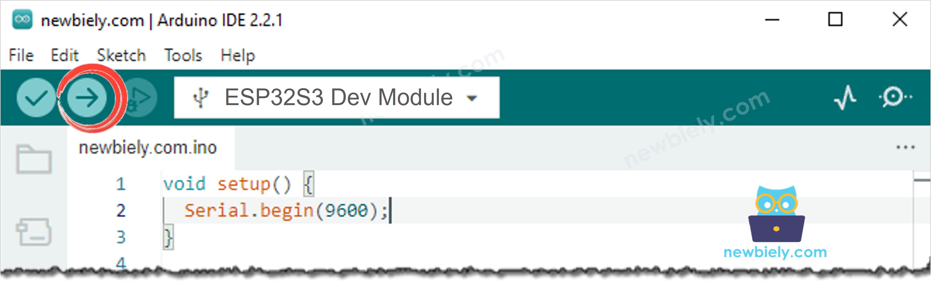
Arduino IDE Upload Code
  1. Press and hold the button for a few seconds, then release it.
  2. Watch the LED. It lights while you hold the button and goes dark when you let go.
  3. Tip: open the Serial Monitor at 9600 baud to see the button state printed in real time.
∞
Newbiely | Arduino IDE 2.3.8
──
☐
✕
File
Edit
Sketch
Tools
Help
ESP32S3 Dev Module
Newbiely.ino
···
8 Serial.println("Hello World!");
Output
Serial Monitor
Message (Enter to send message to 'ESP32S3 Dev Module' on 'COM15')
New Line
9600 baud
The button is unpressed The button is unpressed The button is being pressed The button is being pressed The button is unpressed
Ln 11, Col 1
ESP32S3 Dev Module on COM15
2

Code Explanation

Every line of the sketch has a comment that explains it. The key idea is INPUT_PULLUP: it makes the pin read HIGH when the button is free, so a LOW reading means the button is pressed.

Application 2 - The LED changes its state each time the button is pressed

Now the LED should stay in its new state after you release the button. To do that, the code must catch the moment of the press, not the whole time the button is held.

ESP32 S3 Uno Code - Button Toggles LED Without Debouncing

This sketch remembers the last button state. When the state changes from HIGH to LOW, it counts as one press, and the code flips the LED state.

/* * This ESP32 S3 Uno code was developed by newbiely.com * * This ESP32 S3 Uno code is made available for public use without any restriction * * For comprehensive instructions and wiring diagrams, please visit: * https://newbiely.com/tutorials/esp32-s3-uno/esp32-s3-uno-button-led */ #define BUTTON_PIN 14 // The ESP32 S3 Uno pin connected to the button (D7) #define LED_PIN 17 // The ESP32 S3 Uno pin connected to the LED (D3) int led_state = LOW; // the current state of LED int button_state; // the current state of button int prev_button_state; // the previous state of button void setup() { Serial.begin(9600); // initialize serial pinMode(BUTTON_PIN, INPUT_PULLUP); // set ESP32 S3 Uno pin to input pull-up mode pinMode(LED_PIN, OUTPUT); // set ESP32 S3 Uno pin to output mode button_state = digitalRead(BUTTON_PIN); } void loop() { prev_button_state = button_state; // save the last state button_state = digitalRead(BUTTON_PIN); // read new state if(prev_button_state == HIGH && button_state == LOW) { Serial.println("The button is pressed"); // toggle state of LED led_state = !led_state; // control LED arccoding to the toggled state digitalWrite(LED_PIN, led_state); } }

Code Explanation

The comments in the code above explain each line. The line led_state = !led_state flips the LED state in one step. It does the same job as this longer code:

if(led_state == LOW) led_state = HIGH; else led_state = LOW;

Detailed Instructions

  1. Copy the code and paste it into the Arduino IDE.
  2. Upload the code to the ESP32 S3 Uno.
  3. Press and release the button several times.
  4. Watch the LED change its state.
  5. Tip: press the button many times quickly and watch for presses that seem to be missed.

Most of the time, the LED changes once per press. But sometimes one press makes it change several times very fast, or it looks like nothing happened (the LED changed twice, too fast to see). This happens because the metal contacts inside the button bounce for a few milliseconds.

⇒ To fix this, you need to debounce the button.

ESP32 S3 Uno Code - Button Toggles LED With Debouncing

Writing debounce code by hand is tricky for beginners. The ezButton library does the hard part for you. To learn more about why bouncing happens, read the ESP32 S3 Uno - Button Debounce tutorial.

The sketch below uses ezButton with a 50 millisecond debounce time. It ignores the fast bounces and reports only one real press each time, so the LED toggles exactly once.

/* * This ESP32 S3 Uno code was developed by newbiely.com * * This ESP32 S3 Uno code is made available for public use without any restriction * * For comprehensive instructions and wiring diagrams, please visit: * https://newbiely.com/tutorials/esp32-s3-uno/esp32-s3-uno-button-led */ #include <ezButton.h> #define BUTTON_PIN 14 // The ESP32 S3 Uno pin connected to the button (D7) #define LED_PIN 17 // The ESP32 S3 Uno pin connected to the LED (D3) ezButton button(BUTTON_PIN); // create ezButton object that attach to pin 14 (D7); int led_state = LOW; // the current state of LED void setup() { Serial.begin(9600); // initialize serial pinMode(LED_PIN, OUTPUT); // set ESP32 S3 Uno pin to output mode button.setDebounceTime(50); // set debounce time to 50 milliseconds } void loop() { button.loop(); // MUST call the loop() function first if(button.isPressed()) { Serial.println("The button is pressed"); // toggle state of LED led_state = !led_state; // control LED arccoding to the toggleed sate digitalWrite(LED_PIN, led_state); } }

Detailed Instructions

  1. Install the ezButton library. See how to install the ezButton library.
  2. Copy the code and paste it into the Arduino IDE.
  3. Upload the code to the ESP32 S3 Uno by clicking the Upload button.
  4. Press and release the button several times.
  5. Watch the LED. It now toggles exactly once for each press.
  6. Tip: if a press is still counted twice, raise the value in button.setDebounceTime(50) to 80 or 100.
∞
Newbiely | Arduino IDE 2.3.8
──
☐
✕
File
Edit
Sketch
Tools
Help
ESP32S3 Dev Module
Newbiely.ino
···
8 Serial.println("Hello World!");
Output
Serial Monitor
Message (Enter to send message to 'ESP32S3 Dev Module' on 'COM15')
New Line
9600 baud
The button is pressed The button is pressed The button is pressed
Ln 11, Col 1
ESP32S3 Dev Module on COM15
2

Video Tutorial

Watch the video below to see this ESP32 S3 Uno project step by step.

FAQ

Why does the code use pin 14 and 17 instead of 7 and 3?

The ESP32 S3 Uno uses Uno header labels on the board, but the chip uses GPIO numbers in code. Header D7 is GPIO14 and header D3 is GPIO17. So the code writes 14 for the button and 17 for the LED.

Do I need a resistor for the button on the ESP32 S3 Uno?

No. The code uses INPUT_PULLUP, which turns on the internal pull-up resistor of the ESP32 S3 Uno. Just connect one button leg to D7 and the other to GND.

Can I use a 5V button module with the ESP32 S3 Uno?

The ESP32 S3 Uno pins are not 5V tolerant. A plain push button is fine because it only connects the pin to GND. If you use a button module with its own VCC pin, power it from 3.3V, not 5V.

Why does my LED sometimes toggle twice with one press?

The button contacts bounce for a few milliseconds when you press them. The code sees several fast presses and flips the LED several times. Use the ezButton version of the code to debounce the button.

What if my project needs more pins than the Uno headers give?

The ESP32 S3 Uno has two extra rows of holes with more GPIOs: GPIO15 and GPIO16 (I/O, PWM, analog), GPIO45 and GPIO35 to GPIO42 (I/O, PWM), and GPIO47/GPIO48 (output only, PWM). Solder pin headers to them and write the GPIO number in code. For more buttons, use GPIO35 to GPIO42 or GPIO15/GPIO16, and never GPIO47/GPIO48 because they are output only. For more LEDs, GPIO35 to GPIO42 are good choices. Be careful with two things. First, GPIO47/GPIO48 may run at 1.8V instead of 3.3V on some modules (especially ones with "V" in the name, like R8V or R16V), so 3.3V devices can be damaged or act strangely. Second, GPIO0, GPIO3 (D6), GPIO45 and GPIO46 (D9) are boot strapping pins, and a wrong connection can stop the board from booting or uploading code. Use the other extra pins first.

Does the ezButton library work on the ESP32 S3 Uno?

Yes. ezButton uses only standard Arduino functions like digitalRead() and millis(), so it works the same as on the UNO R4. Install it from the Library Manager in the Arduino IDE.

Troubleshooting

Problem Possible Cause Solution
No COM port in Arduino IDE USB driver missing or bad cable Install the CP210x or CH340 driver, try a data USB cable, or hold BOOT while pressing RESET
LED never lights LED is the wrong way round or wrong pin in code Put the long leg (anode) to the resistor and D3, and use 17 in the code
LED is always on Button wired between D7 and 3.3V instead of GND Connect the second button leg to GND
Serial Monitor shows random pressed and unpressed Button not on D7 or loose wire, so the pin floats Check the wire to D7 (GPIO14) and push it firmly into the breadboard
LED toggles twice or misses presses Button bounce Use the ezButton code and raise the debounce time if needed
Code does not compile with ezButton.h error ezButton library not installed Install ezButton from the Library Manager
Serial Monitor shows strange characters Wrong baud rate Set the Serial Monitor to 9600 baud
Code does not upload Wrong board selected Choose ESP32S3 Dev Module from the esp32 by Espressif Systems core

※ OUR MESSAGES

  • As freelancers, We are AVAILABLE for HIRE. See how to outsource your project to us
  • Please feel free to share the link of this tutorial. However, Please do not use our content on any other websites. We invested a lot of effort and time to create the content, please respect our work!