
ESP32 S3 UNO - LED Matrix
This ESP32 S3 Uno LED matrix tutorial shows you how to connect a MAX7219 dot matrix display to the ESP32 S3 Uno form board and control it with Arduino code. You will drive an 8x8 LED matrix module or a 32x8 LED matrix display, and show text, numbers and scrolling messages on it. The same code also works for 16x8 or 64x8 sizes after one small change.
In this tutorial, you will:
- Wire an 8x8 and a 32x8 FC-16 LED matrix to the ESP32 S3 Uno
- Install the MD_Parola and MD_MAX72XX libraries in Arduino IDE
- Show left, center, right and inverted text and numbers on the dot matrix display
- Make a long message scroll across the LED display
- Change the code for other matrix sizes
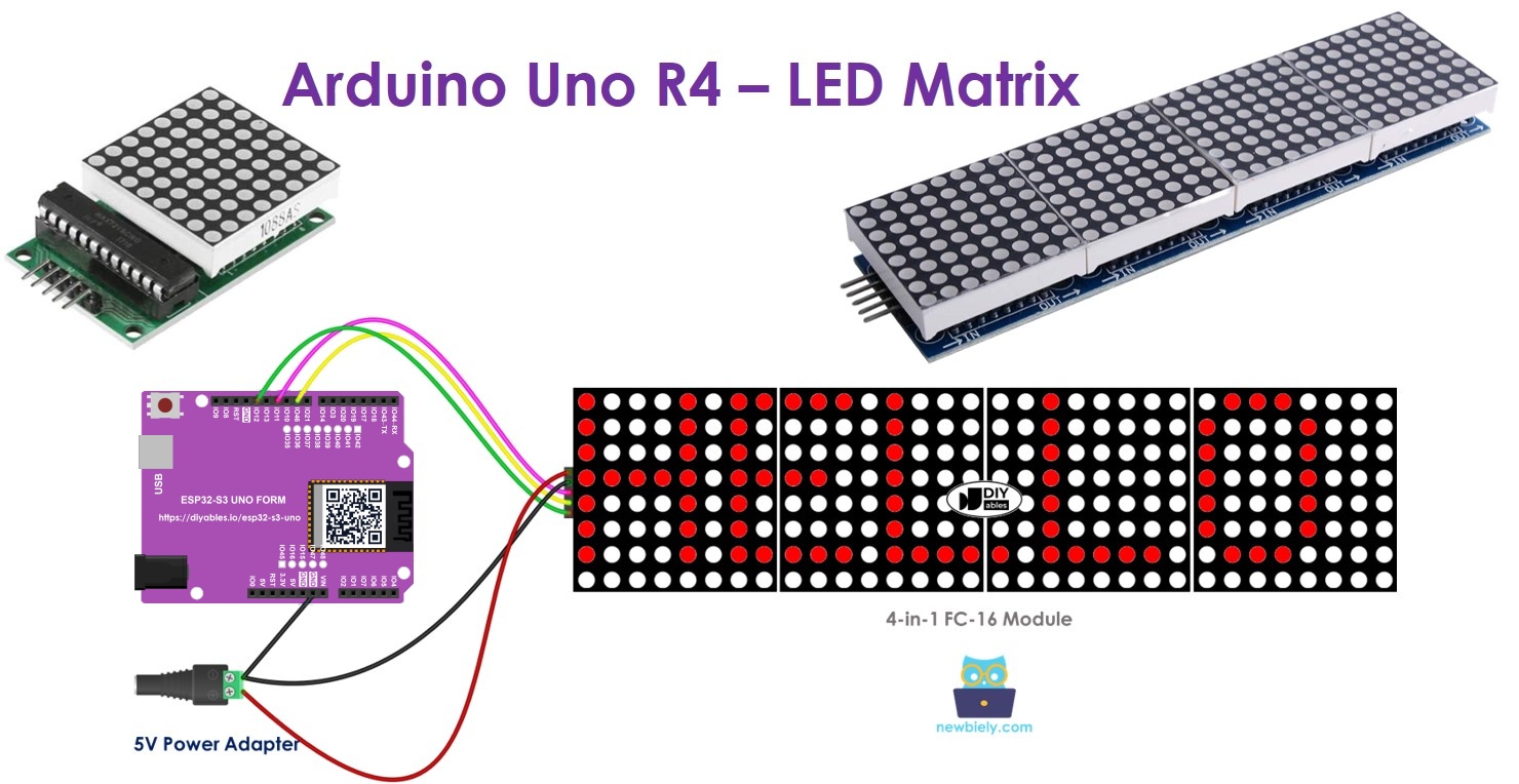
This page is about external LED matrix modules. The ESP32 S3 Uno has no built-in LED matrix, so you need one of the modules listed below.
Hardware Preparation
Or you can buy the following kits:
| 1 | × | DIYables Sensor Kit (18 sensors/displays) |
Additionally, some of these links are for products from our own brand, DIYables .
Overview of LED Matrix
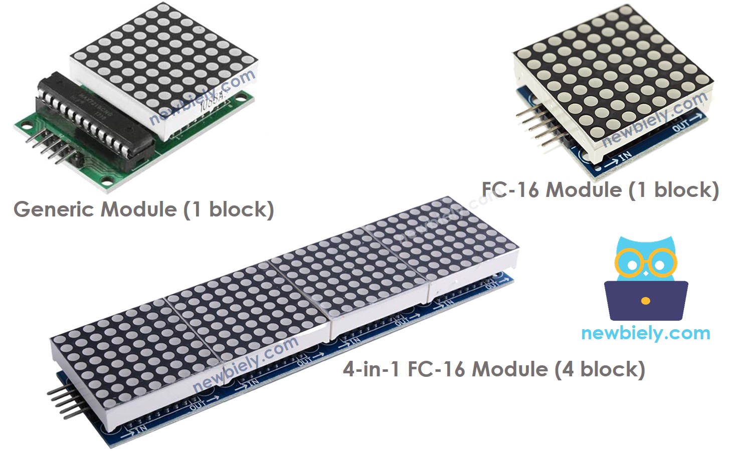
There are many kinds of LED matrix, but the one most makers use is the matrix driven by the MAX7219 chip. It is cheap, easy to chain, and has good libraries, so it is a great match for the ESP32 S3 Uno.
Blocks
The basic unit of this display is called a block. One block is a grid of 8x8 LEDs (64 LEDs in total), and one MAX7219 chip controls it. Blocks come in two main styles: the generic module and the FC-16 module. The code must know which style you have.
Chaining blocks
A display can be a single block, or many blocks linked in a chain. You can buy ready-made displays with 4 or 8 blocks already joined, or you can buy single blocks and connect them yourself to get the size you want. Either way, you tell your ESP32 S3 Uno code how many blocks are in the chain.
Pinout
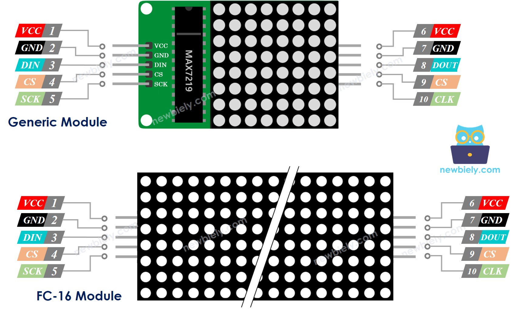
Each block has two groups of pins: an input group that takes data in, and an output group that passes data to the next block. Knowing the two groups makes chaining easy.
Input pins
VCC goes to 5V and GND goes to GND. DIN is the data pin, and it connects to the SPI MOSI pin of the ESP32 S3 Uno. CS (Chip Select) can go to any digital pin. CLK is the clock pin, and it connects to the SPI clock (SCK) pin.
Output pins
VCC, GND, CS and CLK connect to the same pins on the next block. DOUT (Data Out) connects to the DIN pin of the next block.
ESP32 S3 Uno Pinout
The image below shows the pinout of the ESP32 S3 Uno form board. Use it to find the Uno header pins (D9, D11, D13…) and their GPIO numbers while you wire the LED matrix.

Wiring Diagram
How you wire the display depends on how many blocks it has and how they are joined. In every case, only the input group of the first block connects to the ESP32 S3 Uno.
Single block (8x8)
Connect the input pin group to the ESP32 S3 Uno and leave the output pin group free.
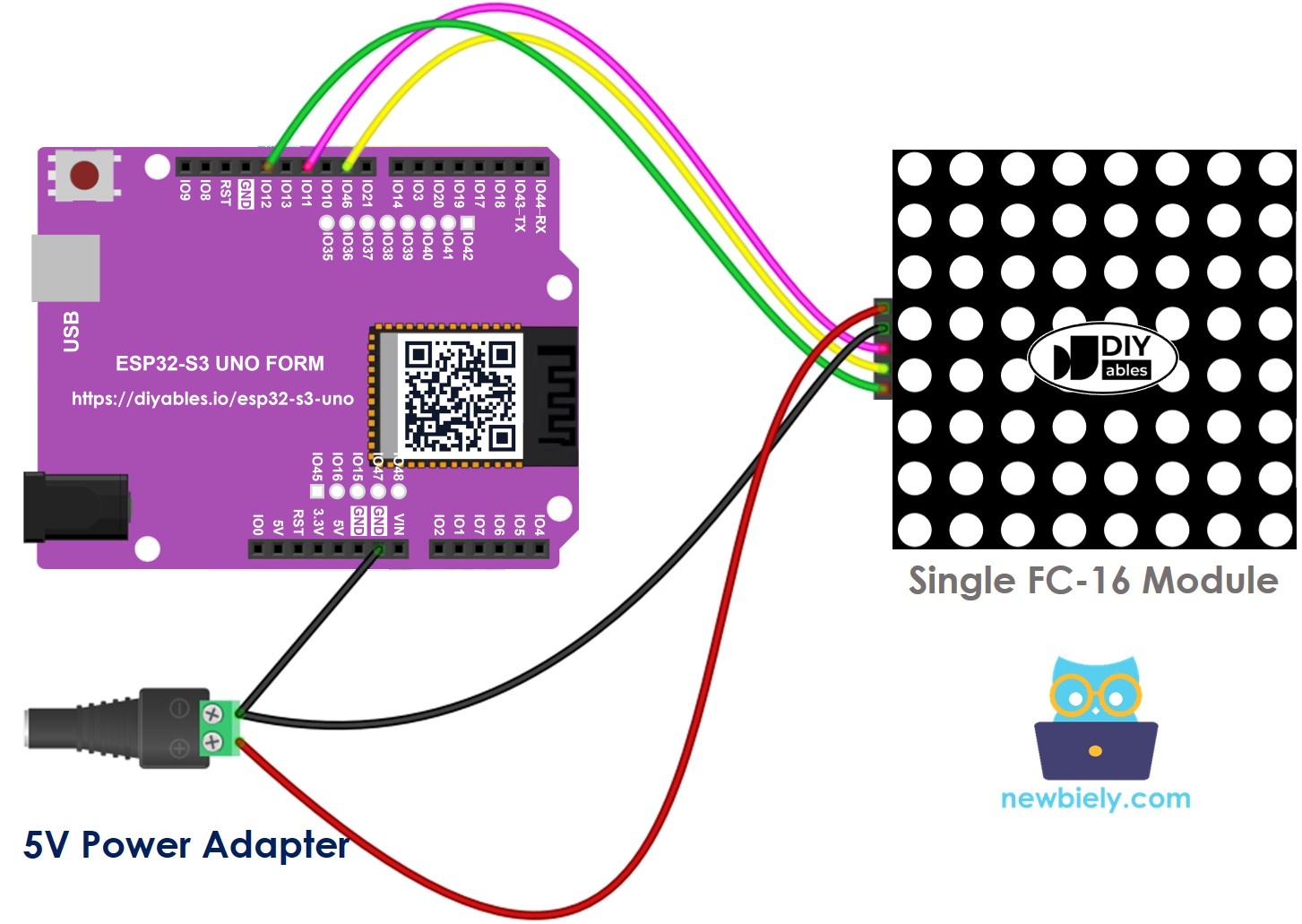
This image is created using Fritzing. Click to enlarge image
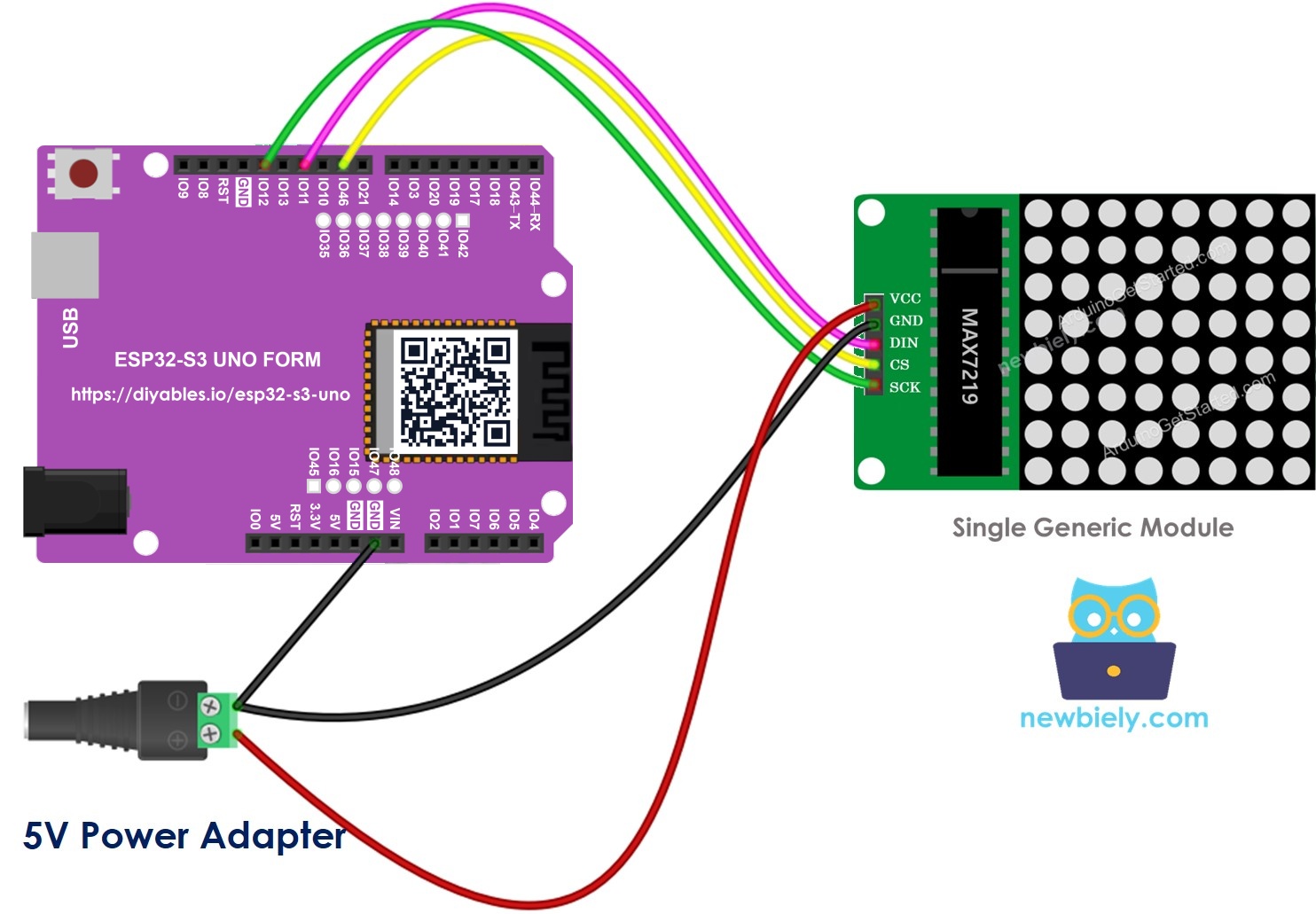
This image is created using Fritzing. Click to enlarge image
Ready-made multi-block display (32x8)
Connect the input pin group to the ESP32 S3 Uno and leave the output pin group free.
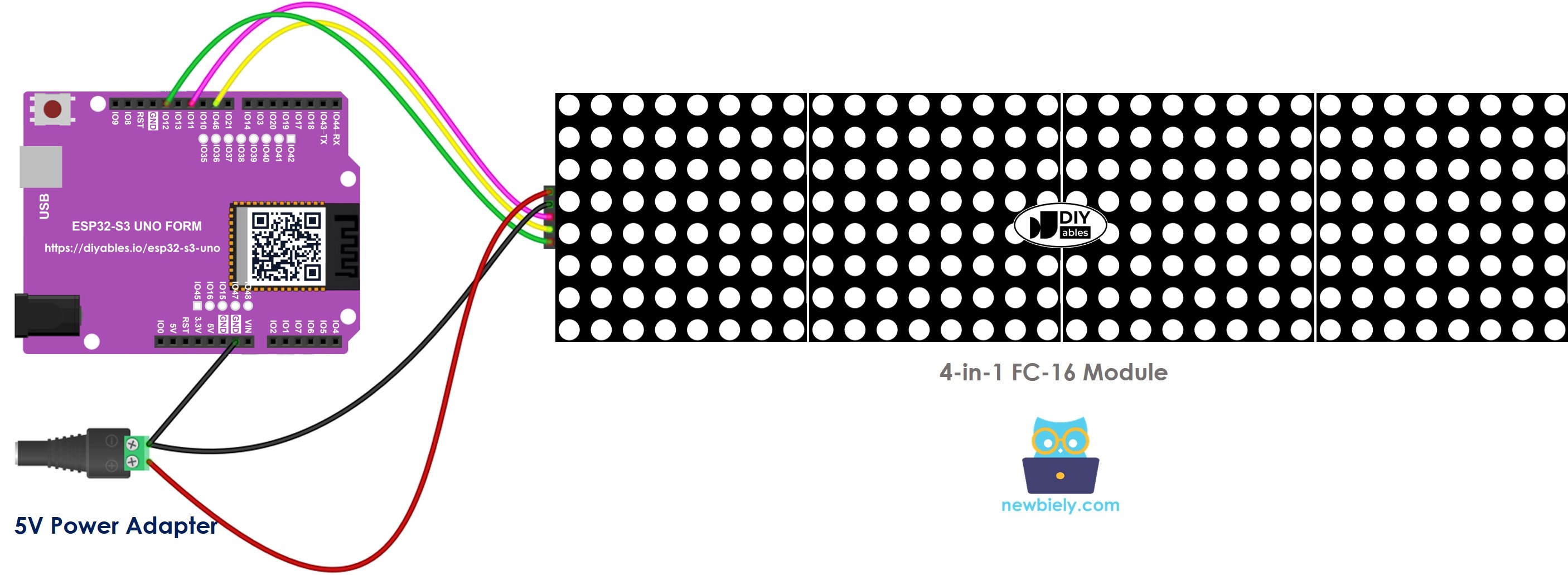
This image is created using Fritzing. Click to enlarge image
Display built from single blocks
- Connect the input pin group of the first block to the ESP32 S3 Uno.
- Connect the output pin group of each block to the input pin group of the next block.
- Leave the output pin group of the last block free.
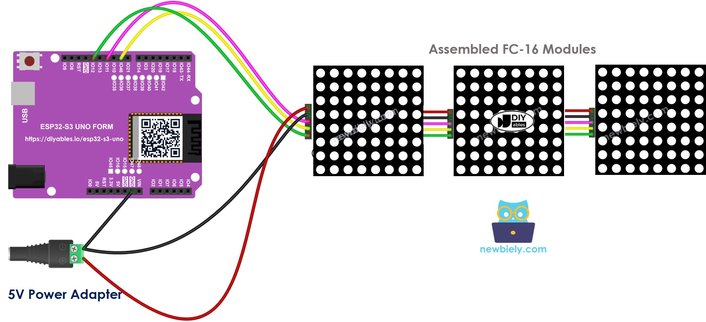
This image is created using Fritzing. Click to enlarge image
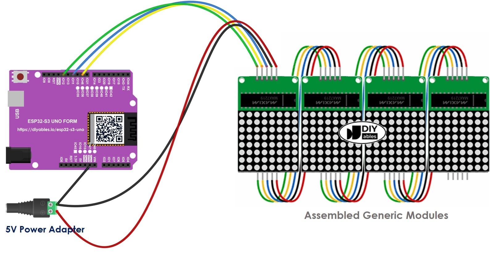
This image is created using Fritzing. Click to enlarge image
| LED Matrix Pin | ESP32 S3 Uno Pin |
|---|---|
| VCC | 5V (external 5V supply) |
| GND | GND |
| DIN | D11 (GPIO11, SPI MOSI) |
| CS | D9 (GPIO46) |
| CLK | D13 (GPIO12, SPI SCK) |
Power
The display can draw up to 1 A at full brightness. That is too much for the 5V pin of the ESP32 S3 Uno, so use an external 5V power supply instead. One 5V adapter can power both the LED matrix and the ESP32 S3 Uno. Always connect the GND of the supply, the matrix and the board together.
SPI pins
The display talks to the ESP32 S3 Uno over SPI. DIN goes to D11 (GPIO11) and CLK goes to D13 (GPIO12), which are the default SPI MOSI and SCK pins, so the library needs no pin change. CS can be any free digital pin; this tutorial uses D9 (GPIO46).
WARNING
D9 (GPIO46) is a boot strapping pin on the ESP32 S3 Uno. The board reads it at power-up to pick the boot mode. The CS line of the matrix is normally fine here, but if your board does not boot or will not upload code while the matrix is connected, unplug the CS wire, upload, and plug it back in. You can also move CS to another free pin and change CS_PIN in the code.
WARNING
The ESP32 S3 Uno uses 3.3V logic, and its pins are NOT 5V tolerant. The signals here only go from the board to the matrix, so the board is safe. A MAX7219 powered at 5V usually accepts 3.3V signals, but if the display shows random dots or stays blank, add a 3.3V to 5V logic level shifter on DIN, CS and CLK.
How To Program For LED Matrix
Driving a MAX7219 matrix by hand takes a lot of code. The MD_Parola and MD_MAX72XX libraries do the hard part for you, so your sketch only needs a few lines. Here is what each part of the setup looks like.
- Include the two libraries.
- Pick your hardware type: GENERIC_HW or FC16_HW.
- Set the number of blocks. A 4-in-1 display has 4 blocks.
- Set the ESP32 S3 Uno pin that drives the CS pin. Here it is D9, which is GPIO46. Always write the GPIO number in code.
- Create an MD_Parola object for the display.
- Start the display in setup().
After that, you can show text, numbers and effects. The next sections show full examples.
ESP32 S3 Uno - LED Matrix Code
This sketch is made for a 32x8 FC-16 display with four blocks. It shows "Left", "Center" and "Right" with matching alignment, then inverted text, then a number, two seconds each. For an 8x8, 16x8 or 64x8 display, just change MAX_DEVICES to 1, 2 or 8.
Detailed Instructions
- New to the ESP32 S3 Uno? Follow ESP32 S3 Uno - Getting Started first.
- Wire it up as shown in the diagram.
- Connect the board to your computer with a USB Type-C cable.
- Open Arduino IDE, choose the ESP32S3 Dev Module board and the correct COM port.
- Open the Library Manager by clicking the Libraries icon on the left bar.
- Install MD_Parola: search for "MD_Parola", find the MD_Parola library and click Install.
- Search for MD_Parola created by majicDesigns and click the Install button.
- Install the dependency: when asked to install MD_MAX72XX too, click Install All.
- Copy the code above and paste it into Arduino IDE.
- Upload the code by clicking the Upload button.
- Watch the display cycle through the text and the number.
- Tip: if the letters look mirrored or upside down, change FC16_HW to GENERIC_HW (or the other way round) and upload again.
ESP32 S3 Uno LED Matrix Code – Scrolling Text
A long message does not fit on a 32x8 display at once. The scrolling effect fixes that: the text slides across the screen from right to left, so you can show a message of any length.
This sketch scrolls "Hello, DIYables" across the display. The displayAnimate() call moves the text one step each time loop() runs, and displayReset() starts the scroll again when it reaches the end.
For more text effects, see the MD_Parola Library Reference.
Video Tutorial
Watch the video below to see this ESP32 S3 Uno project step by step.
The demo in the video is a falling-blocks game on a 32x8 FC-16 display. Three buttons move the piece left, move it right, and rotate it (hold the rotate button for a fast drop). A buzzer plays sounds for moves, cleared lines and game over. The buttons use the internal pull-up resistors.
| Part | ESP32 S3 Uno Pin |
|---|---|
| LED matrix CS | D9 (GPIO46) |
| LED matrix DIN | D11 (GPIO11) |
| LED matrix CLK | D13 (GPIO12) |
| Left button | D2 (GPIO18) |
| Right button | D3 (GPIO17) |
| Rotate button | D4 (GPIO19) |
| Buzzer | D6 (GPIO3) |
WARNING
This demo uses two boot strapping pins: D6 (GPIO3) for the buzzer and D9 (GPIO46) for the matrix CS. If the board does not boot or upload with everything connected, unplug the wires on these two pins, upload, then plug them back in.
FAQ
Can I power the LED matrix from the ESP32 S3 Uno 5V pin?
Only for a small test at low brightness. A 32x8 display can draw up to 1 A at full brightness, which is too much for the board. Use an external 5V supply and connect its GND to the ESP32 S3 Uno GND.
Does the MAX7219 LED matrix work with 3.3V logic from the ESP32 S3 Uno?
In most cases, yes. The ESP32 S3 Uno sends 3.3V signals, and most MAX7219 modules powered at 5V read them correctly. If you see random dots or a blank screen, add a logic level shifter on DIN, CS and CLK, or lower the wire length.
Which ESP32 S3 Uno pins should I use for DIN and CLK?
Use D11 (GPIO11) for DIN and D13 (GPIO12) for CLK. These are the default SPI MOSI and SCK pins of the ESP32 S3 Uno, the same header spots as on an Arduino Uno. CS can go to any free digital pin; just write its GPIO number in CS_PIN.
How do I use an 8x8 or 64x8 display instead of 32x8?
Change MAX_DEVICES to the number of blocks: 1 for 8x8, 2 for 16x8, 8 for 64x8. The wiring stays the same, because extra blocks are chained from the output pins of the previous block.
Why does my text look mirrored or in the wrong order?
The hardware type in the code does not match your module. Switch between FC16_HW and GENERIC_HW and upload again. FC-16 modules are the most common ones.
What if my project needs more pins than the Uno headers give?
The ESP32 S3 Uno has two extra rows of holes with more GPIOs: GPIO15 and GPIO16 (I/O, PWM, analog), GPIO45 and GPIO35–GPIO42 (I/O, PWM), and GPIO47/GPIO48 (output only, PWM). Solder pin headers to use them and write the GPIO number in code. For this project, GPIO35–GPIO42 are good for a second matrix CS pin or for game buttons; do not use GPIO47/GPIO48 for buttons because they are output only. Two warnings: GPIO47/GPIO48 may run at 1.8V instead of 3.3V on some modules (especially ones with "V" in the name, like R8V or R16V), so 3.3V devices can be damaged or act strangely. Also, GPIO0, GPIO3 (D6), GPIO45 and GPIO46 (D9) are boot strapping pins, and a wrong connection can stop the board from booting or uploading code. Use the other extra pins first.
Troubleshooting
| Problem | Possible Cause | Solution |
|---|---|---|
| No COM port in Arduino IDE | Missing USB driver or the board is not in upload mode | Install the CP210x or CH340 driver, or hold BOOT while pressing RESET, then upload again |
| Board does not boot or upload with the matrix connected | CS is on D9 (GPIO46), a boot strapping pin | Unplug the CS wire while uploading, or move CS to another free pin and change CS_PIN |
| Display stays dark | No 5V power, GND not shared, or wrong DIN and CLK pins | Check the 5V supply, join all GNDs, and wire DIN to D11 (GPIO11) and CLK to D13 (GPIO12) |
| Random dots or flicker | Weak 3.3V signals or long wires | Use shorter wires, or add a logic level shifter on DIN, CS and CLK |
| Text mirrored or blocks in the wrong order | Wrong hardware type | Switch between FC16_HW and GENERIC_HW |
| Only part of the text shows | MAX_DEVICES does not match the number of blocks | Set MAX_DEVICES to the real block count |
| Board resets at high brightness | Power drawn from the board 5V pin | Use an external 5V supply or lower setIntensity() |
| Compile error MD_Parola.h not found | Library not installed | Install MD_Parola and click Install All to add MD_MAX72XX |