
ESP32 S3 UNO - Blink LED
This ESP32 S3 Uno LED blink tutorial shows you how to wire an LED to the ESP32 S3 Uno form board and control it with Arduino code. You will turn the LED on, turn it off, and make it blink every half second. The same method works to control many other on/off devices.
In this tutorial, you will:
- Learn the two pins of an LED and how it lights up
- Wire an LED and a resistor to the ESP32 S3 Uno
- Set a pin as an output with pinMode()
- Turn the LED on and off with digitalWrite()
- Make the LED blink using delay() in the Arduino IDE
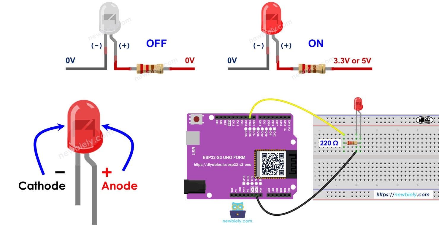
Hardware Preparation
Or you can buy the following kits:
| 1 | × | DIYables Sensor Kit (18 sensors/displays) |
Additionally, some of these links are for products from our own brand, DIYables .
Buy Note: Use the LED Module for easier wiring. It includes an integrated resistor.
Overview of LED
An LED is the simplest output part you can add to a project. Once you can switch an LED, you can switch buzzers, relays and many other devices the same way.
Pinout
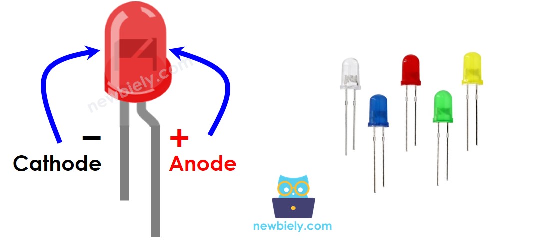
An LED has only two pins, and it works in one direction only. If you swap them, it simply stays dark.
Cathode (-) pin
This is the negative pin. Connect it to GND (0V).
Anode (+) pin
This is the positive pin. The voltage on this pin decides if the LED is on or off.
How It Works
Connect the cathode (-) to GND first. After that, only the anode (+) controls the LED.
When the anode gets 0V (GND), no current flows and the LED is off. When the anode gets the supply voltage (VCC), current flows and the LED is on.
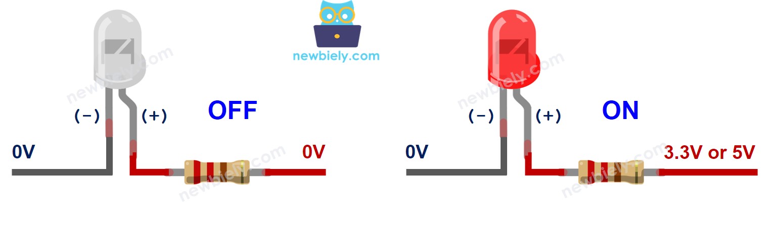
You can also send a PWM signal to the anode. The PWM value then sets how bright the LED glows. You can learn this in the ESP32 S3 Uno - LED - Fade tutorial.
※ NOTE THAT:
Most LEDs need a resistor to limit the current. You can put it between the anode and VCC, or between the cathode and GND. The right value depends on your LED. Some LEDs have a resistor built in, so they may not need an extra one.
ESP32 S3 Uno - LED
A pin of the ESP32 S3 Uno can work as a digital output. Your code then sets it to GND (LOW) or to 3.3V (HIGH). To control an LED, connect one ESP32 S3 Uno pin to the LED anode (+) through a resistor. The ESP32 S3 Uno uses 3.3V logic, which is enough to light a normal LED with a 220 ohm resistor.
ESP32 S3 Uno Pinout
The image below shows the pinout of the ESP32 S3 Uno form board. Use it to find the Uno header pin D9 and its GPIO number before you wire the LED.

Wiring Diagram
Connect the LED and the resistor as shown below. The LED anode goes to pin D9 through the 220 ohm resistor.
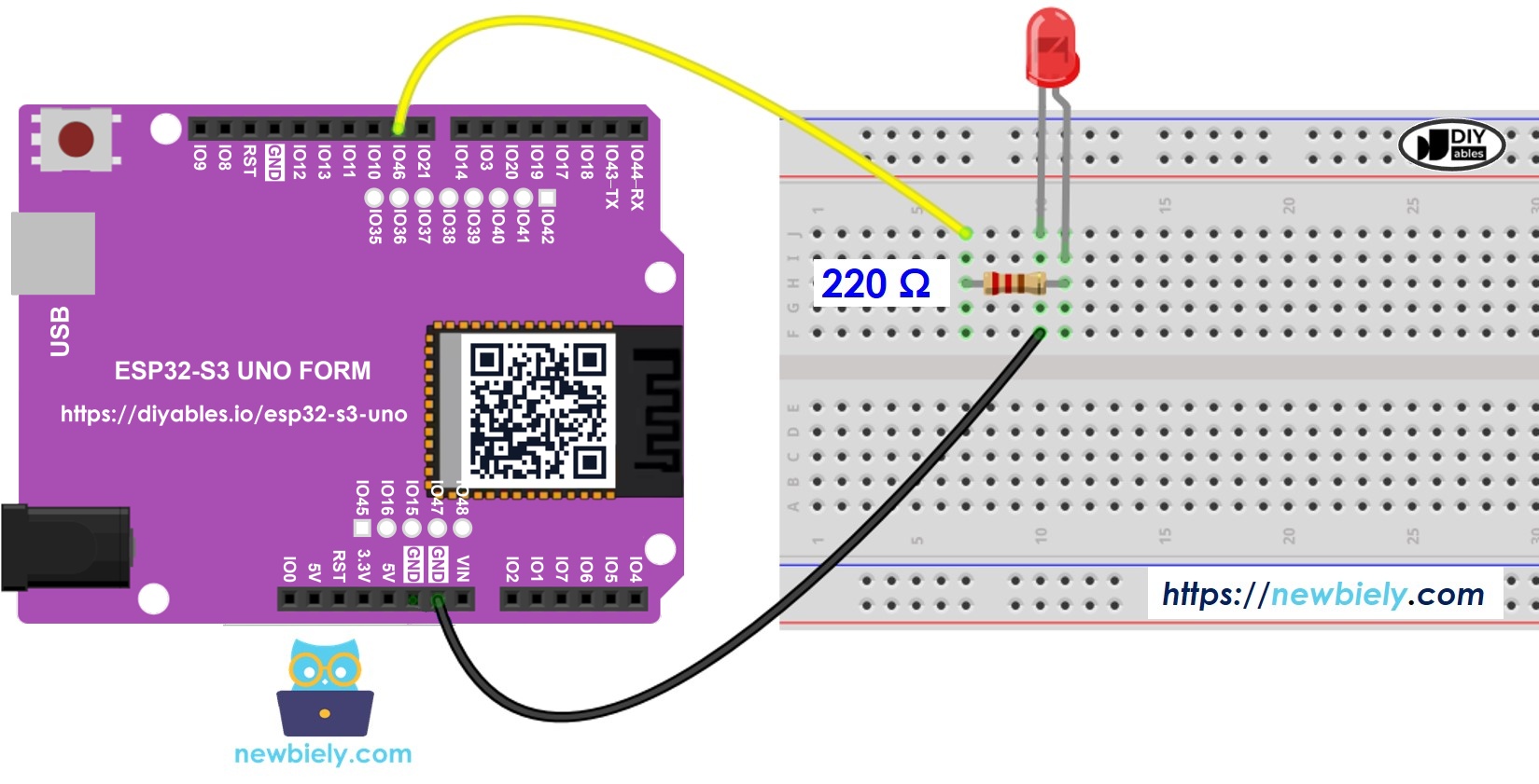
This image is created using Fritzing. Click to enlarge image
| Component Pin | ESP32 S3 Uno Pin |
|---|---|
| LED Anode (+) via 220 ohm resistor | D9 (GPIO46) |
| LED Cathode (-) | GND |
WARNING
Pin D9 is GPIO46 on the ESP32 S3 Uno. It is a boot strapping pin, so the board reads its level at startup. An LED with a resistor to GND is normally fine. But if the board does not boot or upload, remove the LED wire from D9 for a moment, upload the code, then put the wire back.
How To Program
Controlling an LED takes only two functions. You set the pin mode once, and then you write HIGH or LOW whenever you want.
- Set an ESP32 S3 Uno pin as a digital output with pinMode(). For example, for pin D9 (GPIO46):
- Turn the LED off by setting the pin to GND with digitalWrite():
- Turn the LED on by setting the pin to VCC (3.3V) with digitalWrite():
ESP32 S3 Uno Code
The sketch below sets GPIO46 (D9) as an output. In the loop, it turns the LED on for 500 milliseconds and off for 500 milliseconds, so the LED blinks once per second.
Detailed Instructions
- New to the ESP32 S3 Uno? Follow ESP32 S3 Uno - Getting Started first.
- Wire it up as shown in the diagram.
- Connect the board to your computer with a USB Type-C cable.
- Open Arduino IDE, choose the ESP32S3 Dev Module board and the correct COM port.
- Copy the code above and paste it into the Arduino IDE.
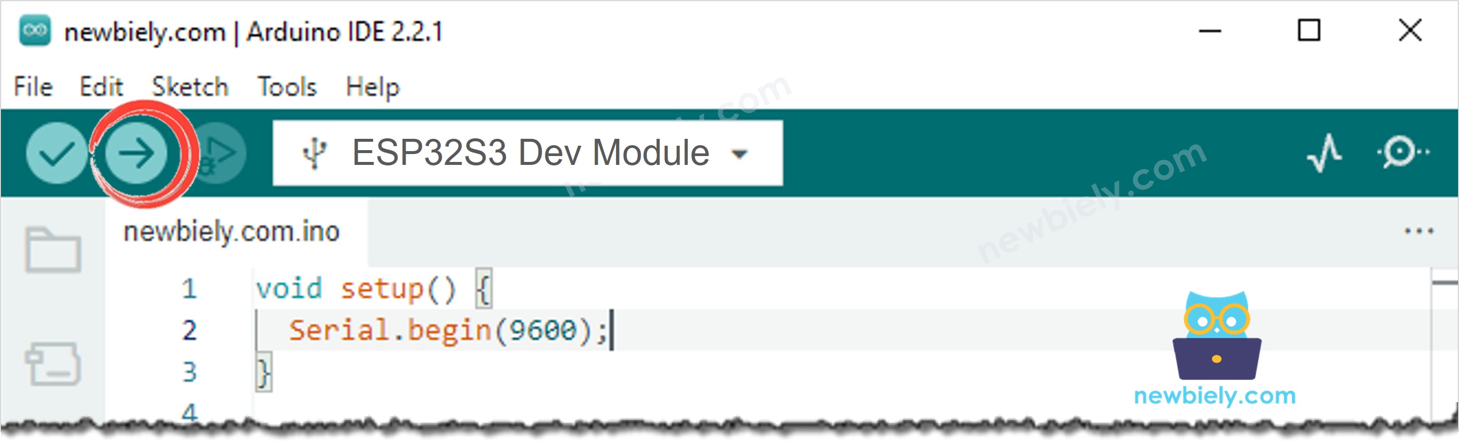
- Upload the code by clicking the Upload button.
- Watch the LED. It should turn on and off every half second.
- Tip: change both delay(500) values to delay(100) and upload again. The LED will blink much faster.
Code Explanation
Each line of the code has a comment that tells you what it does. The #define LED_PIN 46 line keeps the pin number in one place, so you can move the LED to another pin by changing only this line.
※ NOTE THAT:
The code uses delay(). While delay() runs, the ESP32 S3 Uno cannot do anything else. If your project must do several jobs at the same time, avoid blocking code and use the non-blocking method for the ESP32 S3 Uno.
If you want an easier way to control LEDs, you can use the LED library.
Video Tutorial
Watch the video below to see this ESP32 S3 Uno project step by step.
Additional Knowledge
Not every pin is a good choice for an LED. Pick a free pin that is not busy with another job.
Which ESP32 S3 Uno pins can control an LED?
Pins D2 to D13 and A0 to A5 can all work as digital outputs. You can also use the SDA (GPIO8) and SCL (GPIO9) header pins if you do not need I2C.
※ NOTE THAT:
Use each pin for only one job at a time. If a pin already works as a digital input or a PWM output, do not use it for the LED too. Do not use D0 and D1 for an LED, because they are used for serial and USB communication. Also, D6 (GPIO3) and D9 (GPIO46) are boot strapping pins, so check that the board still boots well when something is connected to them.
Function References
FAQ
Why does my LED code use 46 instead of 9?
The ESP32 S3 Uno has the same header labels as an Uno, but the chip uses GPIO numbers. Header pin D9 is GPIO46, so the code must use 46. Check the pinout image when you move the LED to another pin.
Is 3.3V enough to light an LED on the ESP32 S3 Uno?
Yes. A red, yellow or green LED with a 220 ohm resistor lights well at 3.3V. Blue and white LEDs need about 3V, so they may look a little dim, but they still work. Use a smaller resistor (for example 100 ohm) if you need more brightness.
Can I use the built-in LED instead of an external LED?
This tutorial does not use a built-in LED on the ESP32 S3 Uno. Use an external LED on a header pin, like D9 here or D13 (GPIO12). Then you know exactly which pin you control.
What if my project needs more pins than the Uno headers give?
The ESP32 S3 Uno has two extra rows of holes with more GPIOs: GPIO15 and GPIO16 (I/O, PWM, analog), GPIO45 and GPIO35 to GPIO42 (I/O, PWM), and GPIO47/GPIO48 (output only, PWM). Solder pin headers to them and write the GPIO number in code. For extra LEDs, GPIO35 to GPIO42 and GPIO15/GPIO16 are good choices. Be careful with two things. First, GPIO47/GPIO48 may run at 1.8V instead of 3.3V on some modules (especially ones with "V" in the name, like R8V or R16V), so 3.3V devices can be damaged or act strangely. Second, GPIO0, GPIO3 (D6), GPIO45 and GPIO46 (D9) are boot strapping pins, and a wrong connection can stop the board from booting or uploading code. Use the other extra pins first.
How do I make the LED blink faster or slower?
Change the number inside delay(). It is in milliseconds, so delay(1000) waits one second and delay(100) waits a tenth of a second. Use different values for on and off time if you want a short flash.
Can I connect many LEDs to the ESP32 S3 Uno?
Yes, give each LED its own pin and its own resistor. Keep the total current low, because each ESP32 S3 Uno pin can only supply a small current. For many LEDs or high-power LEDs, use a transistor or an LED driver.
Troubleshooting
| Problem | Possible Cause | Solution |
|---|---|---|
| No COM port in Arduino IDE | USB driver missing or bad cable | Install the CP210x or CH340 driver, try a data USB cable, or hold BOOT while pressing RESET |
| Upload fails or board does not start | The LED circuit on D9 (GPIO46) affects the boot strapping pin | Remove the wire from D9, upload the code, then reconnect it |
| LED never lights | LED is the wrong way round | Turn the LED so the long leg (anode) goes to the resistor and D9 |
| LED never lights | Wrong pin number in code | Use 46 for D9, not 9 |
| LED is very dim | Resistor value too high | Use a 220 ohm resistor or smaller, but not below 100 ohm |
| LED is always on or always off | Loose breadboard wire or missing GND | Check the GND wire and push all wires firmly into the breadboard |
| Code does not compile | Wrong board selected | Choose ESP32S3 Dev Module from the esp32 by Espressif Systems core |