
ESP32 S3 UNO - MP3 Player
This ESP32 S3 Uno MP3 player tutorial shows you how to build a small music box with a serial MP3 player module, a Micro SD card and a speaker. The ESP32 S3 Uno form board sends simple serial commands, and the MP3 module reads the song from the card and plays it through the speaker. You can start with one song and then add play, pause, next and previous buttons.
In this tutorial, you will:
- Wire a serial MP3 player module and a speaker to the ESP32 S3 Uno
- Play a song from a Micro SD card with Arduino code
- Send MP3 commands over a hardware serial port (UART)
- Add play, pause, next and previous buttons to control the music
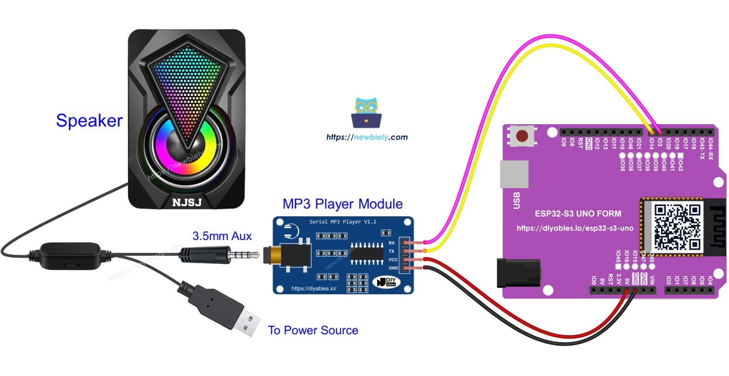
Hardware Preparation
Or you can buy the following kits:
| 1 | × | DIYables Sensor Kit (18 sensors/displays) |
Additionally, some of these links are for products from our own brand, DIYables .
Overview of Serial MP3 Player Module and Speaker
Before you wire anything, it helps to know what each part does. The MP3 module does all the hard audio work, so the ESP32 S3 Uno only needs to send short commands. The speaker just needs an audio cable and its own power.
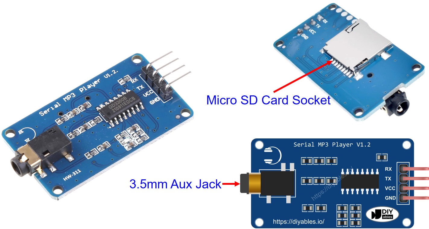
Serial MP3 Player Module Pinout
The serial MP3 player module has three sides: a control side for the board, an audio output for the speaker, and a card slot for your music.
Control interface (4 pins)
The RX pin receives commands, so it goes to a TX pin on the ESP32 S3 Uno. The TX pin sends data back, so it goes to an RX pin on the board. The VCC pin powers the module (the module accepts about 3.2V to 5.2V), and the GND pin goes to ground (0V).
Audio output
A 3.5mm Aux female jack sends the audio signal to the speaker.
Micro SD card slot
The card socket sits on the back of the module. Your MP3 files live here.
Speaker Pinout
A typical Aux speaker has two connections. The audio connection is a 3.5mm Aux male plug that goes into the MP3 module. The power connection can be USB, a 5V adapter or another type of power input, depending on the speaker.
How It Works
The idea is simple: the songs sit on the card, and the ESP32 S3 Uno tells the MP3 module which one to play. You only need to prepare the hardware once.
- Copy your songs or recordings to a Micro SD card.
- Put the Micro SD card into the MP3 player module.
- Connect the MP3 player module to the ESP32 S3 Uno.
- Plug the speaker into the MP3 module.
- Give the speaker power.
Every MP3 file on the card gets a number, starting from 0, that sets the play order. The ESP32 S3 Uno sends 8-byte command frames to the module over a serial line. The module understands commands such as start playing, stop (pause), play next, play previous and set volume. It then decodes the MP3 file into an audio signal and sends it to the speaker through the 3.5mm Aux jack.
Why a hardware serial port?
Many MP3 player examples use SoftwareSerial. That library does not exist on the ESP32 S3 Uno. Instead, the code uses the hardware port Serial1, which you can attach to almost any GPIO. Here it uses the same header pins as the original wiring: D7 (GPIO14) for RX and D6 (GPIO3) for TX.
ESP32 S3 Uno Pinout
The image below shows the pinout diagram of the ESP32 S3 Uno form board. Use it to find the Uno header pins (D2, D6, D7…) and their GPIO numbers when you wire the MP3 player.

Wiring Diagram
Connect the MP3 module to the board as shown below. The serial lines cross over: the module TX goes to the board RX pin, and the module RX goes to the board TX pin.
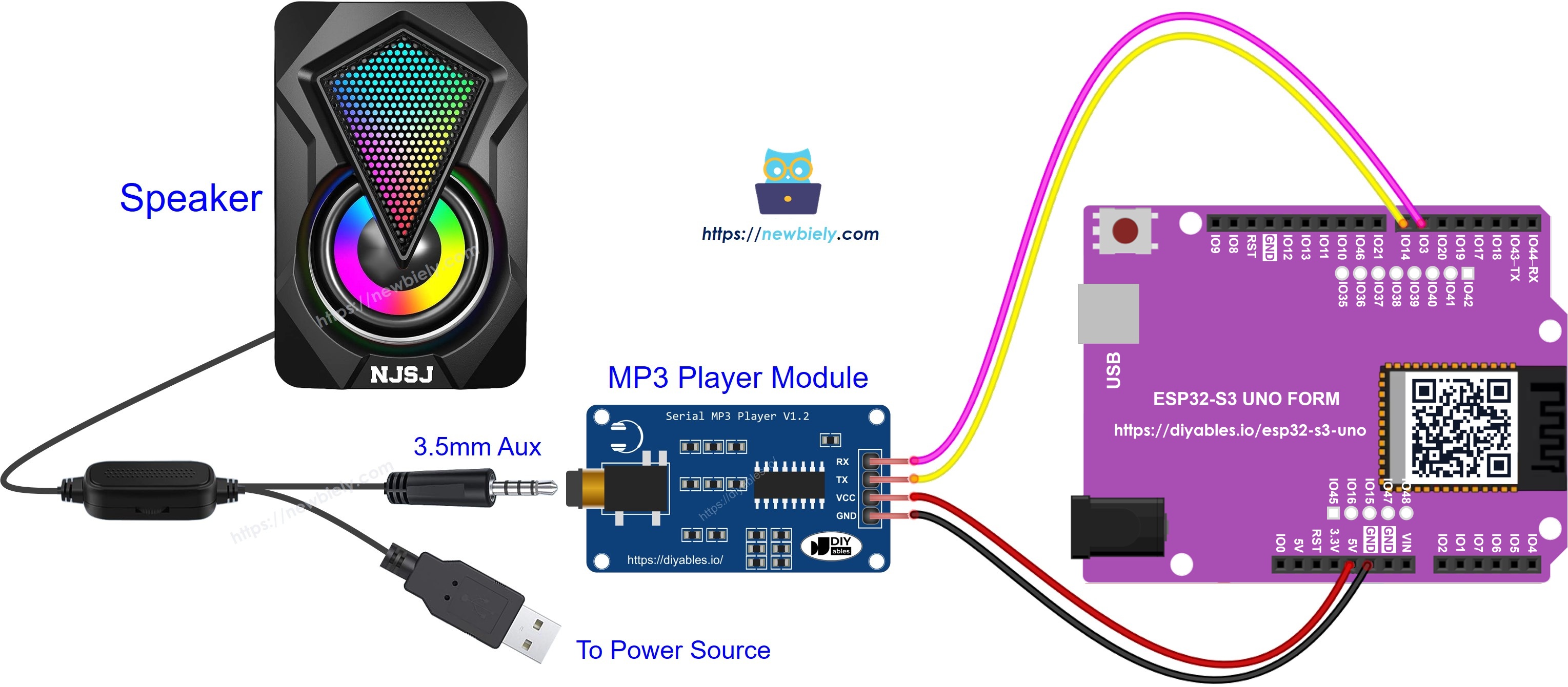
This image is created using Fritzing. Click to enlarge image
| MP3 Module Pin | ESP32 S3 Uno Pin |
|---|---|
| VCC | 5V |
| GND | GND |
| TX | D7 (GPIO14) - through a level converter |
| RX | D6 (GPIO3) |
WARNING
The ESP32 S3 Uno pins are NOT 5V tolerant. When the MP3 module is powered from 5V, its TX pin sends 5V signals into D7 (GPIO14). Put a 5V to 3.3V level converter (or a 1kΩ / 2kΩ voltage divider) on this line. Another option is to power the module VCC from the 3.3V pin, because the module works from about 3.2V, then the TX signal is already 3.3V. The RX line (board to module) is safe as it is.
WARNING
D6 is GPIO3 on the ESP32 S3 Uno. It is a boot strapping pin, which the chip reads at startup. Here it is used as the serial TX output to the module, which is normally fine. If the board ever fails to boot or upload while the module is connected, unplug the wire on D6, upload, then plug it back.
ESP32 S3 Uno Code - Play Music
This first sketch is the simplest test. It sets up the serial port to the module, selects the Micro SD card and starts the first song. The mp3_command() function packs each command into an 8-byte frame and sends it to the module.
The line mp3.begin(9600, SERIAL_8N1, ESP32_S3_UNO_RX, ESP32_S3_UNO_TX) starts UART1 at 9600 baud on GPIO14 (RX) and GPIO3 (TX). The commented-out lines show the other commands. Remove the // from one of them to try pause, next, previous or volume.
Detailed Instructions
- New to the ESP32 S3 Uno? Follow ESP32 S3 Uno - Getting Started first.
- Prepare the card as described in How It Works: copy MP3 files to the Micro SD card and insert it into the module.
- Wire it up as shown in the diagram.
- Connect the board to your computer with a USB Type-C cable.
- Open Arduino IDE, choose the ESP32S3 Dev Module board and the correct COM port.
- Copy the code above and paste it into Arduino IDE.
- Upload the code by clicking the Upload button.
- Listen to the speaker. The first song on the card starts playing.
- Tip: if you hear nothing, check that the speaker is switched on and has power, and that the module TX and RX wires are not swapped.
ESP32 S3 Uno Code - Play Music with control buttons
Now you can turn the test into a real player. This version adds four push buttons: play, pause, next and previous. The ezButton library handles debouncing, so each press sends exactly one command.
Each button uses the internal pull-up resistor, so wire one leg to the GPIO and the other leg to GND. When you press a button, the sketch prints the action on the Serial Monitor and sends the matching command to the module. Install the ezButton library from the Library Manager before you upload.
Here is the wiring for this version:
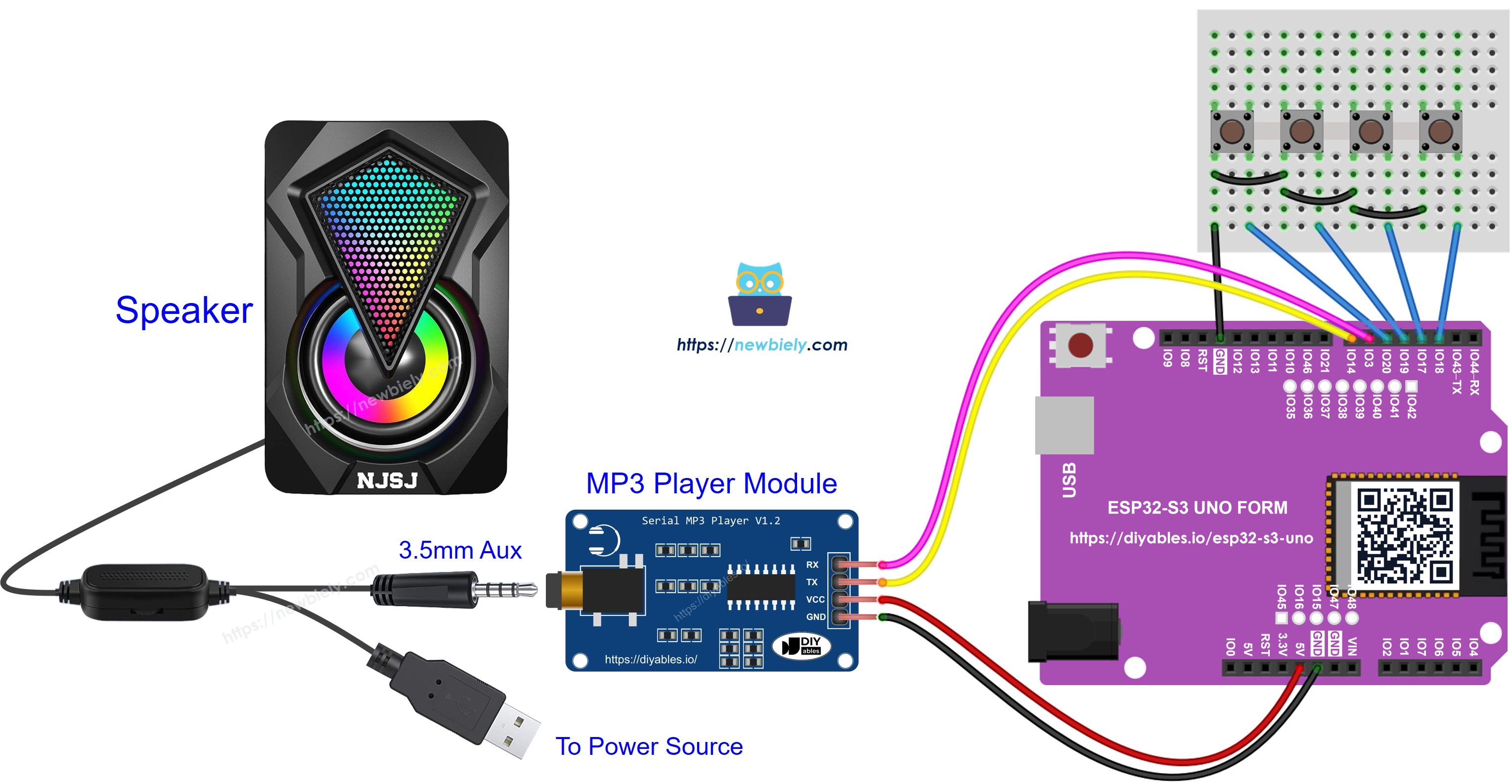
This image is created using Fritzing. Click to enlarge image
| Part | ESP32 S3 Uno Pin |
|---|---|
| MP3 module VCC | 5V |
| MP3 module GND | GND |
| MP3 module TX | D7 (GPIO14) - through a level converter |
| MP3 module RX | D6 (GPIO3) |
| Play button | D2 (GPIO18) |
| Pause button | D3 (GPIO17) |
| Next button | D4 (GPIO19) |
| Previous button | D5 (GPIO20) |
| Other leg of each button | GND |
WARNING
The same two warnings apply here: use a level converter on the module TX line when the module runs on 5V, and remember that D6 (GPIO3) is a boot strapping pin.
When you press the buttons, the Serial Monitor (9600 baud) shows output like this:
You can grow this project with more features:
- Add a potentiometer to change the volume. See the ESP32 S3 Uno Potentiometer tutorial.
- Add an IR remote controller so you can control the music from your sofa.
- Add an RFID reader and cards to build an RFID MP3 player. See the ESP32 S3 Uno RFID tutorial.
Video Tutorial
Watch the video below to see this ESP32 S3 Uno project step by step.
Function References
FAQ
Can I use SoftwareSerial for the MP3 module on the ESP32 S3 Uno?
No. SoftwareSerial is not part of the esp32 by Espressif Systems core. Use a hardware port instead, like Serial1.begin(9600, SERIAL_8N1, RX, TX). The ESP32 S3 Uno can route UART1 to almost any GPIO, so you keep the same header pins as the UNO R4 wiring.
Can I power the MP3 player module from 3.3V?
Yes, in most cases. The module works from about 3.2V to 5.2V. Powering it from the 3.3V pin makes its TX signal 3.3V, so you do not need a level converter. If the module resets or the sound cuts out at high volume, power it from 5V and add a level converter on the TX line.
Is the MP3 module safe for the ESP32 S3 Uno pins?
Only if the signal into the board is 3.3V or less. The ESP32 S3 Uno pins are not 5V tolerant. The module TX line goes into the board, so it needs a level converter or a voltage divider when the module runs on 5V. The board TX line going into the module is fine.
How do I change the volume in code?
Send the set volume command, for example mp3_command(CMD_SET_VOLUME, 20);. The value goes from 0 (silent) to 30 (loudest). You can read a potentiometer with analogRead(), which gives 0 to 4095 on the ESP32 S3 Uno, and map it to 0 to 30.
What if my project needs more pins than the Uno headers give?
The ESP32 S3 Uno has two extra rows of holes with more GPIOs. GPIO15 and GPIO16 are I/O, PWM and analog. GPIO45 and GPIO35 to GPIO42 are I/O and PWM. GPIO47 and GPIO48 are output only, with PWM. Solder pin headers to use them and write the GPIO number in code. For this MP3 player, GPIO35 to GPIO42 are good for extra buttons, and GPIO15 or GPIO16 suit a volume potentiometer. Do not use GPIO47/GPIO48 for buttons, because they are output only. Two warnings: (1) GPIO47 and GPIO48 may run at 1.8V instead of 3.3V on some modules (especially ones with "V" in the name, like R8V or R16V), so 3.3V devices can be damaged or act strangely. (2) GPIO0, GPIO3 (D6), GPIO45 and GPIO46 (D9) are boot strapping pins, and a wrong connection can stop the board from booting or uploading code. Use the other extra pins first.
In what order does the module play my songs?
The module numbers the files in the order they were copied to the card, starting from 0. To control the order, format the card, then copy the files one by one in the order you want.
Troubleshooting
| Problem | Possible Cause | Solution |
|---|---|---|
| No COM port shows up in Arduino IDE | Missing USB driver or board not in upload mode | Install the CP210x or CH340 driver, try another cable, or hold BOOT while you press RESET |
| Upload fails or board does not boot with the module connected | D6 (GPIO3) is a boot strapping pin | Unplug the wire on D6, upload, then plug it back in |
| No sound at all | Speaker off, no power to the speaker, or Aux plug loose | Turn the speaker on, power it, and push the Aux plug all the way in |
| Module does not react to commands | TX and RX wires swapped or wrong baud rate | Module TX goes to D7 (GPIO14), module RX goes to D6 (GPIO3), and use 9600 baud |
| Module plays nothing even with good wiring | Card not detected or wrong file format | Use a FAT32 Micro SD card with MP3 files and reinsert it before power-up |
| Board acts strangely or resets | 5V signal from the module TX into a 3.3V pin | Add a level converter on the TX line or power the module from 3.3V |
| Compile error about SoftwareSerial.h | Code written for other boards | Use the code on this page, which uses Serial1 instead |
| Buttons do nothing | ezButton library missing or button not wired to GND | Install ezButton and wire the second button leg to GND |