
ESP32 S3 UNO - Relay
This ESP32 S3 Uno relay tutorial shows you how to switch high-voltage devices, like light bulbs, fans, electromagnetic locks and linear actuators, on and off with a small control signal. You will connect a 1-channel relay module to the ESP32 S3 Uno form board and learn how its normally open and normally closed modes work. At the end, a 12V LED strip blinks under the control of your Arduino code.
In this tutorial, you will:
- Learn how a relay module works and what its pins do
- Connect a high-voltage device to the relay in normally open mode
- Wire a one-channel relay to the ESP32 S3 Uno
- Write Arduino code that turns the relay on and off with digitalWrite()
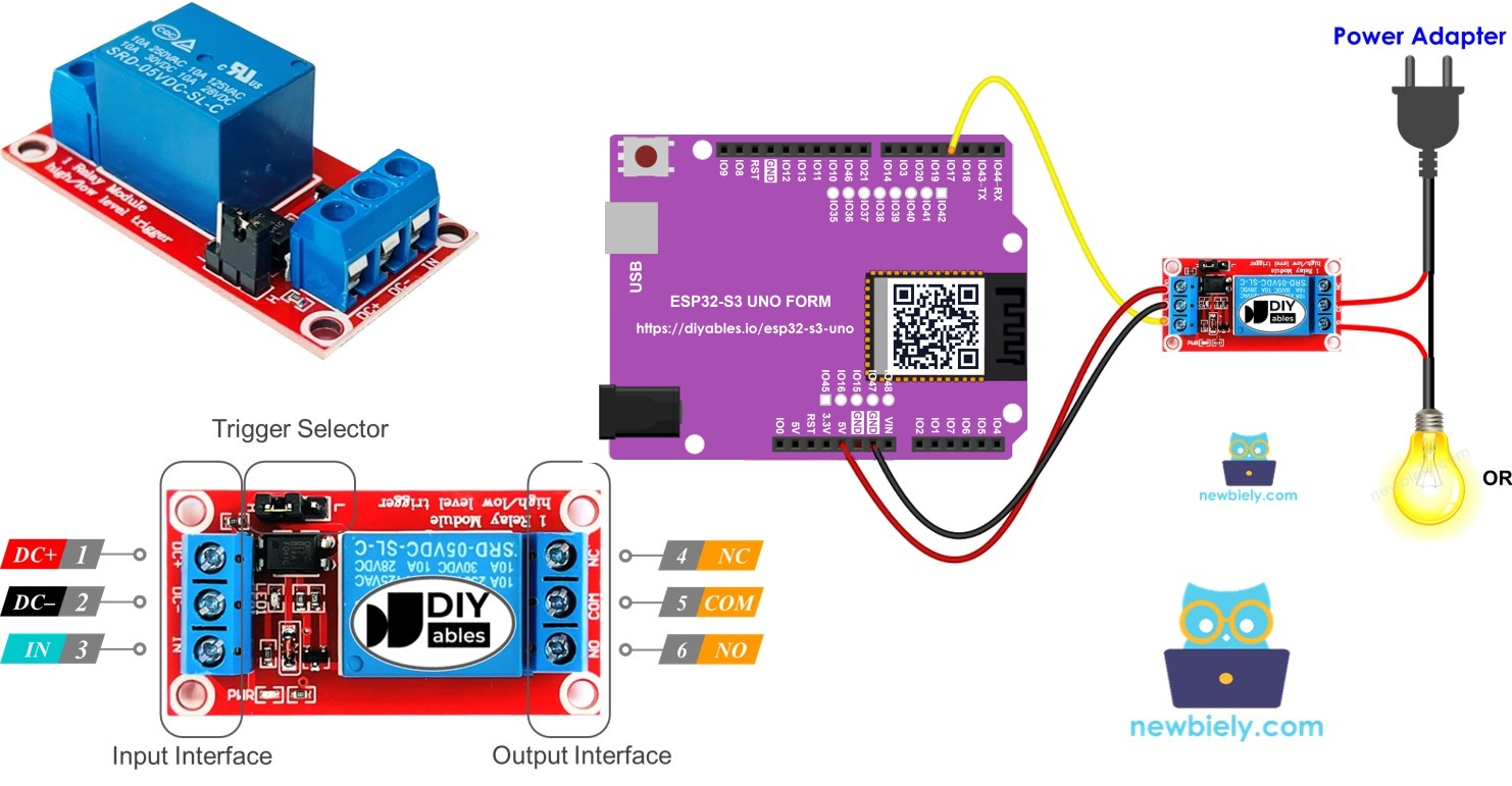
Hardware Preparation
| 1 | × | ESP32 S3 Uno-form Board | |
| 1 | × | USB Cable Type-A to Type-C (for USB-A PC) | |
| 1 | × | USB Cable Type-C to Type-C (for USB-C PC) | |
| 1 | × | Relay | |
| 1 | × | LED Strip | |
| 1 | × | 12V Power Adapter | |
| 1 | × | DC Power Jack | |
| 1 | × | Breadboard | |
| 1 | × | Jumper Wires |
Or you can buy the following kits:
| 1 | × | DIYables Sensor Kit (18 sensors/displays) |
Additionally, some of these links are for products from our own brand, DIYables .
Overview of Relay
A microcontroller pin can only give a few milliamps at 3.3V. That is far too little to run a lamp, a fan or a lock. A relay solves this problem: it is an electric switch that your ESP32 S3 Uno can open and close from code.
You can think of the relay as a bridge. On one side sits the ESP32 S3 Uno with its low-voltage signal. On the other side sits a device that needs high voltage or high current. The two sides stay electrically apart, so you can switch big loads safely and automatically.
WARNING
Mains electricity can kill. Only work on mains-powered projects if you really know what you are doing. If you are not sure, stop and ask an experienced person for help.
Some relays can switch both AC and DC loads, but for testing we recommend a DC device of 24V or less.
Relay Pinout
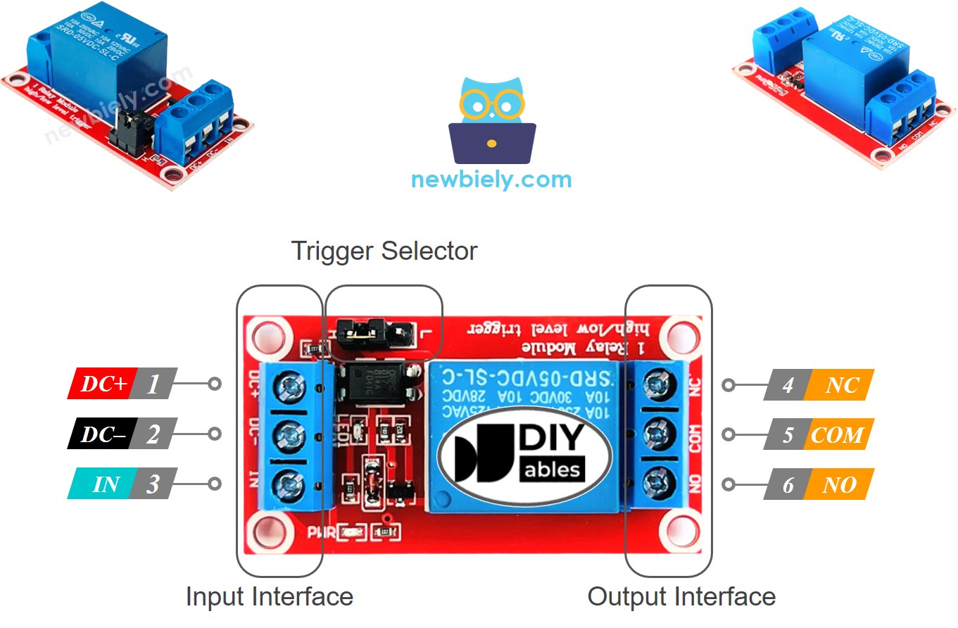
A relay module has two groups of pins. The input group works at low voltage and talks to the ESP32 S3 Uno. The output group carries the high voltage of your device.
Input pins (low voltage)
These three pins connect to the ESP32 S3 Uno. The DC- pin goes to GND (0V). The DC+ pin goes to VCC (5V on most modules). The IN pin receives the control signal from the ESP32 S3 Uno.
Output pins (high voltage)
These three pins usually sit in a screw terminal and connect to your device. The COM pin is the common pin, used in both modes. The NO pin is the normally open pin, used in normally open mode. The NC pin is the normally closed pin, used in normally closed mode.
You never need all three output pins at once. For normally open mode, you use COM and NO. For normally closed mode, you use COM and NC.
Some relay modules support both a LOW level trigger and a HIGH level trigger. These modules usually have a jumper that lets you pick one of the two.
※ NOTE THAT:
Pin order is not the same on every relay module. Different makers place the pins in different orders. Always read the labels printed on your relay and wire it by those labels.
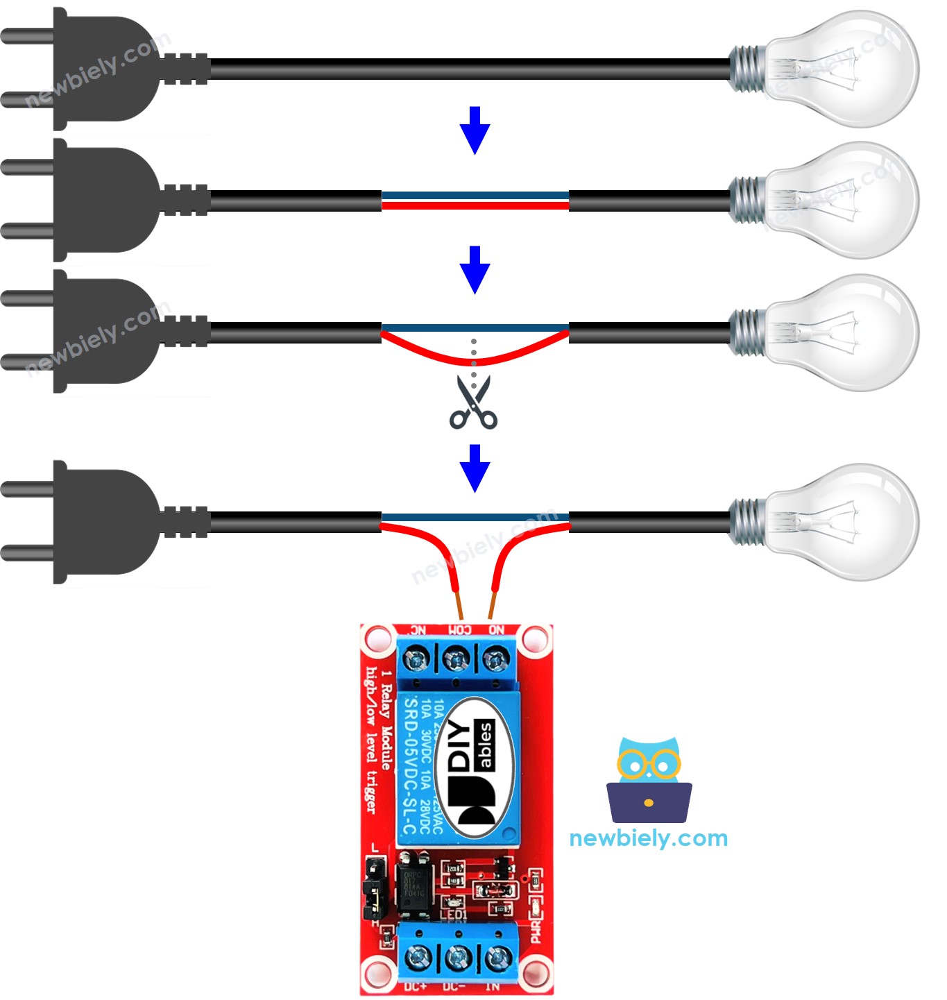
How to Connect the High Voltage Device to Relay
The picture below shows how the device, its power supply and the relay output pins form one loop. The relay simply opens or closes this loop.
How It Works
A relay can behave in different ways. It depends on the module you bought and on how you wire it. Two settings decide its behavior: the input mode and the output mode.
The two input modes
The input mode can be LOW level trigger or HIGH level trigger. These two modes work in opposite ways. Not every relay module supports both, and a module runs in only one of them at a time.
The two output modes
The output mode can be normally open or normally closed. These two modes also work in opposite ways. Most relay modules support both.
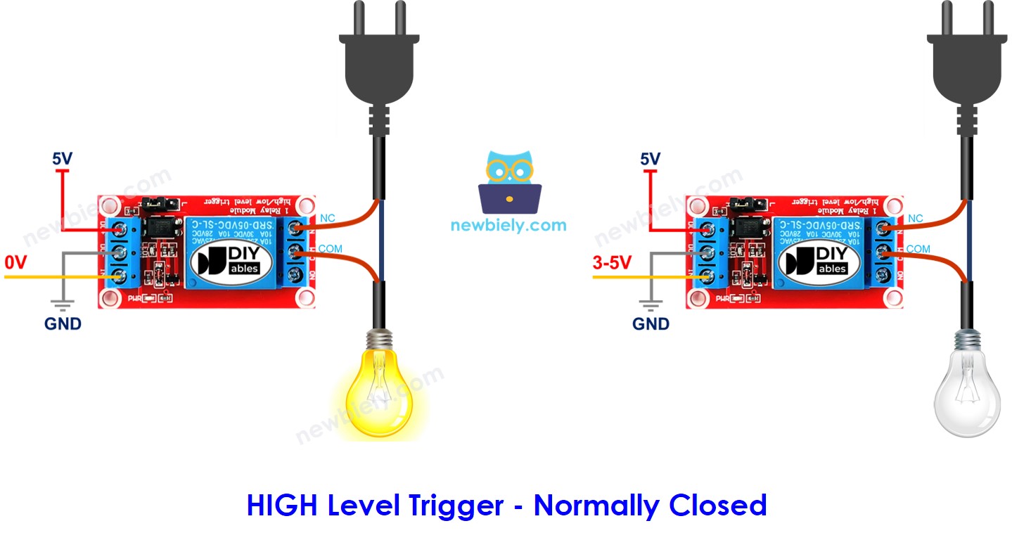
The word "normally" describes the state when the IN pin is at LOW (0V).
If you put the input and output modes together, you get many combinations. For beginners, we suggest the HIGH level trigger with the normally open mode. The sections below explain the HIGH level trigger in detail. The LOW level trigger does exactly the opposite.
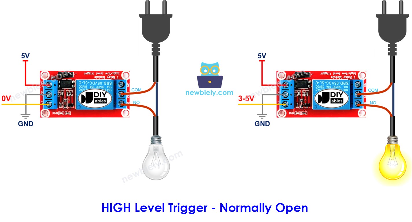
HIGH Level Trigger - Normally Open Mode
For this mode, connect your high-voltage device to the COM pin and the NO pin. When the IN pin is LOW (0V), the switch is open and the device is OFF. When the IN pin is HIGH, the switch closes and the device turns ON.
HIGH Level Trigger - Normally Closed Mode
For this mode, connect your high-voltage device to the COM pin and the NC pin. When the IN pin is LOW (0V), the switch is closed and the device is ON. When the IN pin is HIGH, the switch opens and the device turns OFF.
Summary
The table lists all eight combinations of input mode, output mode and IN pin level.
| Input modes | Output Modes | IN pin (programmable) | Output pins | Relay state | Device state |
|---|---|---|---|---|---|
| HIGH Trigger | Normally Open | LOW | COM and NO pin | ⇒ open | ⇒ OFF |
| HIGH Trigger | Normally Open | HIGH | COM and NO pin | ⇒ closed | ⇒ ON |
| HIGH Trigger | Normally Closed | LOW | COM and NC pin | ⇒ closed | ⇒ ON |
| HIGH Trigger | Normally Closed | HIGH | COM and NC pin | ⇒ open | ⇒ OFF |
| LOW Trigger | Normally Open | LOW | COM and NO pin | ⇒ closed | ⇒ ON |
| LOW Trigger | Normally Open | HIGH | COM and NO pin | ⇒ open | ⇒ OFF |
| LOW Trigger | Normally Closed | LOW | COM and NC pin | ⇒ open | ⇒ OFF |
| LOW Trigger | Normally Closed | HIGH | COM and NC pin | ⇒ closed | ⇒ ON |
Eight cases may look like a lot. As a beginner, you only need the first two rows: HIGH level trigger with normally open. This tutorial focuses on these two cases.
ESP32 S3 Uno - Relay
Controlling a relay from the ESP32 S3 Uno takes very little work. You connect one ESP32 S3 Uno pin to the IN pin of the relay. Then your code sets that pin to LOW or HIGH, and the relay switches the device.
ESP32 S3 Uno Pinout
The image below shows the pinout diagram of the ESP32 S3 Uno form board. Use it to find the D3 header and its GPIO number when you wire the relay.

Wiring Diagram
The relay input side connects to the ESP32 S3 Uno, and the LED strip connects to the relay output with its own 12V power adapter. The signal wire goes to D3.
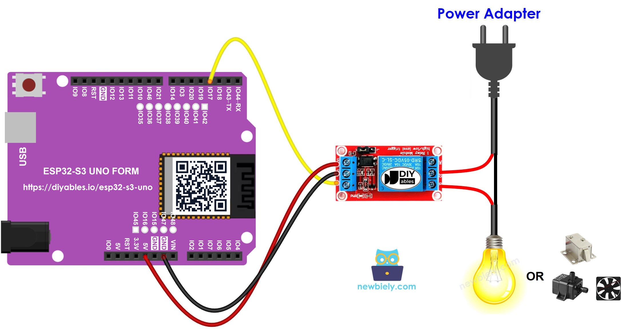
This image is created using Fritzing. Click to enlarge image
| Component Pin | ESP32 S3 Uno Pin |
|---|---|
| Relay DC+ (VCC) | 5V |
| Relay DC- (GND) | GND |
| Relay IN | D3 (GPIO17) |
※ NOTE THAT:
Most relay modules have a 5V coil, so power DC+ from the 5V pin. The IN pin only receives the 3.3V signal from the ESP32 S3 Uno, and most modules switch fine with it. Never connect a 5V signal back into an ESP32 S3 Uno pin, because the ESP32 S3 Uno pins are NOT 5V tolerant.
The LED strip, the 12V power adapter and the DC power jack connect to the COM and NO screw terminals of the relay. Never power the LED strip from the ESP32 S3 Uno.
How To Program For Relay
Driving a relay is the same as driving any digital output. You set the pin mode once, then write LOW or HIGH to it.
- Make the ESP32 S3 Uno pin a digital output with the pinMode() function. For example, for D3 (GPIO17):
- Set the pin to LOW (0V) with the digitalWrite() function:
- Set the pin to HIGH (3.3V) with the digitalWrite() function:
ESP32 S3 Uno Code
The sketch below sets GPIO17 (D3) as an output. In the loop, it turns the relay on for 500 ms and off for 500 ms, again and again, so the LED strip blinks.
Detailed Instructions
Follow these steps in order:
- New to the ESP32 S3 Uno? Follow ESP32 S3 Uno - Getting Started first.
- Wire it up as shown in the diagram.
- Connect the board to your computer with a USB Type-C cable.
- Open Arduino IDE, choose the ESP32S3 Dev Module board and the correct COM port.
- Copy the code and paste it into Arduino IDE.
- Upload the code by clicking the Upload button.
- Check the LED strip. It should blink, and you should hear the relay click twice every second.
- Tip: If the LED strip is on when you expect it off, your relay may be a LOW level trigger module. Move its jumper to HIGH, or swap HIGH and LOW in the code.
Video Tutorial
Watch the video below to see this ESP32 S3 Uno project step by step.
Function References
FAQ
Can the ESP32 S3 Uno drive a 5V relay module?
Yes, in most cases. Power the module from the 5V pin and connect IN to D3 (GPIO17). The 3.3V HIGH signal is enough for most modules with a transistor or optocoupler input. If your relay does not click, use a 3V relay module.
Why is HIGH 3.3V and not 5V like on the UNO R4?
The ESP32 S3 Uno is a 3.3V board, so its output pins go up to 3.3V. The UNO R4 uses 5V logic. Because of this, ESP32 S3 Uno pins are NOT 5V tolerant. Never feed a 5V signal into them.
Which pin should I use for the relay?
This tutorial uses D3, which is GPIO17 in code. Any normal output pin works. Avoid D6 (GPIO3) and D9 (GPIO46), because they are boot strapping pins, and a relay module could stop the board from booting.
What is the difference between normally open and normally closed?
In normally open mode, the device is OFF until the relay is activated. In normally closed mode, the device is ON until the relay is activated. Use normally open for most projects, so the device stays off if the board loses power.
What if my project needs more relays than the Uno headers give?
The ESP32 S3 Uno has two extra rows of holes with more GPIOs. GPIO15 and GPIO16 are I/O, PWM and analog. GPIO45 and GPIO35 to GPIO42 are I/O and PWM. GPIO47 and GPIO48 are output only, with PWM. Solder pin headers to use them and write the GPIO number in code. For extra relays, GPIO35 to GPIO42 are a good choice. Be careful with two things. First, GPIO47 and GPIO48 may run at 1.8V instead of 3.3V on some modules (especially ones with "V" in the name, like R8V or R16V), so 3.3V devices can be damaged or act strangely. Second, GPIO0, GPIO3 (D6), GPIO45 and GPIO46 (D9) are boot strapping pins, and a wrong connection can stop the board from booting or uploading code. Use the other extra pins first.
Can I switch a 220V lamp with this relay?
The relay can switch mains power, but mains voltage is dangerous. Only do it if you know how to work safely with high voltage. For learning, use a 12V LED strip or another low-voltage DC device.
Troubleshooting
| Problem | Possible Cause | Solution |
|---|---|---|
| No COM port in Arduino IDE | USB driver is missing or the board is not in upload mode | Install the CP210x or CH340 driver, or hold BOOT while pressing RESET |
| Relay never clicks | Relay DC+ or DC- is not connected | Power DC+ from 5V and check the GND wire |
| Relay LED lights but it does not click | The 3.3V signal is too weak for this module | Use a 3V relay module or one with a transistor input |
| Relay works the opposite way | The module is set to LOW level trigger | Move the trigger jumper to HIGH, or swap HIGH and LOW in the code |
| Relay clicks but the LED strip stays off | Strip is wired to the wrong terminals or the 12V adapter is off | Use COM and NO, and check the adapter and DC power jack |
| Relay does nothing after upload | Code uses the wrong pin number | Write 17 in code for D3, not 3 |
| Board resets when the relay switches | Power drop from the relay coil or the load | Use a good USB cable or power supply, and keep the 12V load on its own adapter |