Arduino Nano ESP32 - TCS3200D/TCS230 Color Sensor
In this tutorial, we'll explore how to connect the TCS3200D/TCS230 color sensor to Arduino Nano ESP32 for accurate color detection and RGB value measurement.
What you'll accomplish:
- Connecting TCS3200D/TCS230 sensor to Arduino Nano ESP32
- Calibrating the sensor for precise color measurements
- Reading and displaying RGB color values
Hardware Preparation
Or you can buy the following kits:
| 1 | × | DIYables Sensor Kit (18 sensors/displays) |
Additionally, some of these links are for products from our own brand, DIYables .
Overview of TCS3200D/TCS230 Color Sensor
The TCS3200D/TCS230 employs a structured array of 64 photodiodes in an 8×8 configuration for optical color sensing. The array comprises 16 photodiodes with red optical filters, 16 with green filters, 16 with blue filters, and 16 without filters (clear). Color detection works by activating designated filter groups and analyzing the frequency of the output waveform.
Standard TCS3200D sensor modules incorporate white LED arrays that provide consistent illumination to the measurement target, delivering stable readings across different lighting environments and enabling operation in poorly lit conditions.
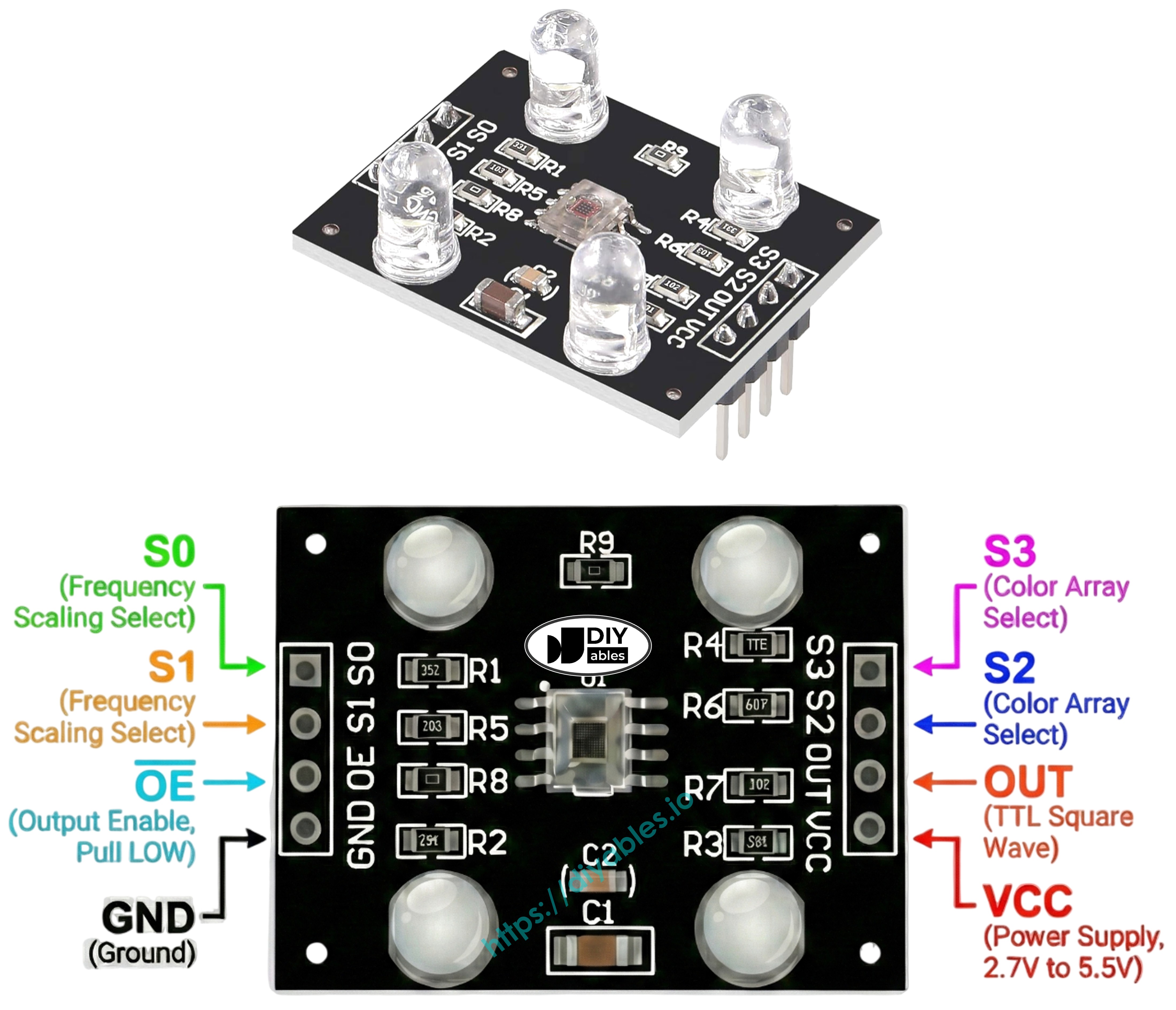
Pinout
Connection terminals on the TCS3200D/TCS230 sensor module:
- VCC pin: Positive power supply (+5V).
- GND pin: Ground reference (0V).
- S0, S1 pins: Frequency scaling configuration pins.
- S2, S3 pins: Color filter activation pins.
- OUT pin: Frequency-encoded square wave output.
- OE pin: Output activation pin (active when LOW). Standard modules hardwire this to GND internally. If floating, connect manually to GND.
How It Works
Sensor functionality relies on two configurable parameters: which color filter to engage and what output frequency range to use. Two control pin pairs manage these settings:
Frequency scaling configuration (S0 and S1 pins):
- S0=LOW, S1=LOW: Sensor powered down
- S0=LOW, S1=HIGH: 2% output scaling
- S0=HIGH, S1=LOW: 20% output scaling
- S0=HIGH, S1=HIGH: 100% output scaling (full frequency)
Color filter activation (S2 and S3 pins):
- S2=LOW, S3=LOW: Red photodiode array active
- S2=LOW, S3=HIGH: Blue photodiode array active
- S2=HIGH, S3=LOW: Clear photodiode array active (unfiltered)
- S2=HIGH, S3=HIGH: Green photodiode array active
The OUT pin generates square wave frequencies within the approximate range of 2 Hz to 500 kHz. Increased light intensity results in elevated frequency output. Arduino's pulseIn() measures pulse duration, which exhibits inverse behavior—brighter illumination yields shorter pulse durations. Through calibration, these pulse measurements transform into familiar 0-255 RGB notation.
Maximizing Measurement Precision
- Establish fixed sensor-to-object distance (optimal: 1-3 cm) with steady angular positioning.
- Activate integrated white LED illumination for reproducible results.
- Shield from fluctuating external light sources for improved accuracy.
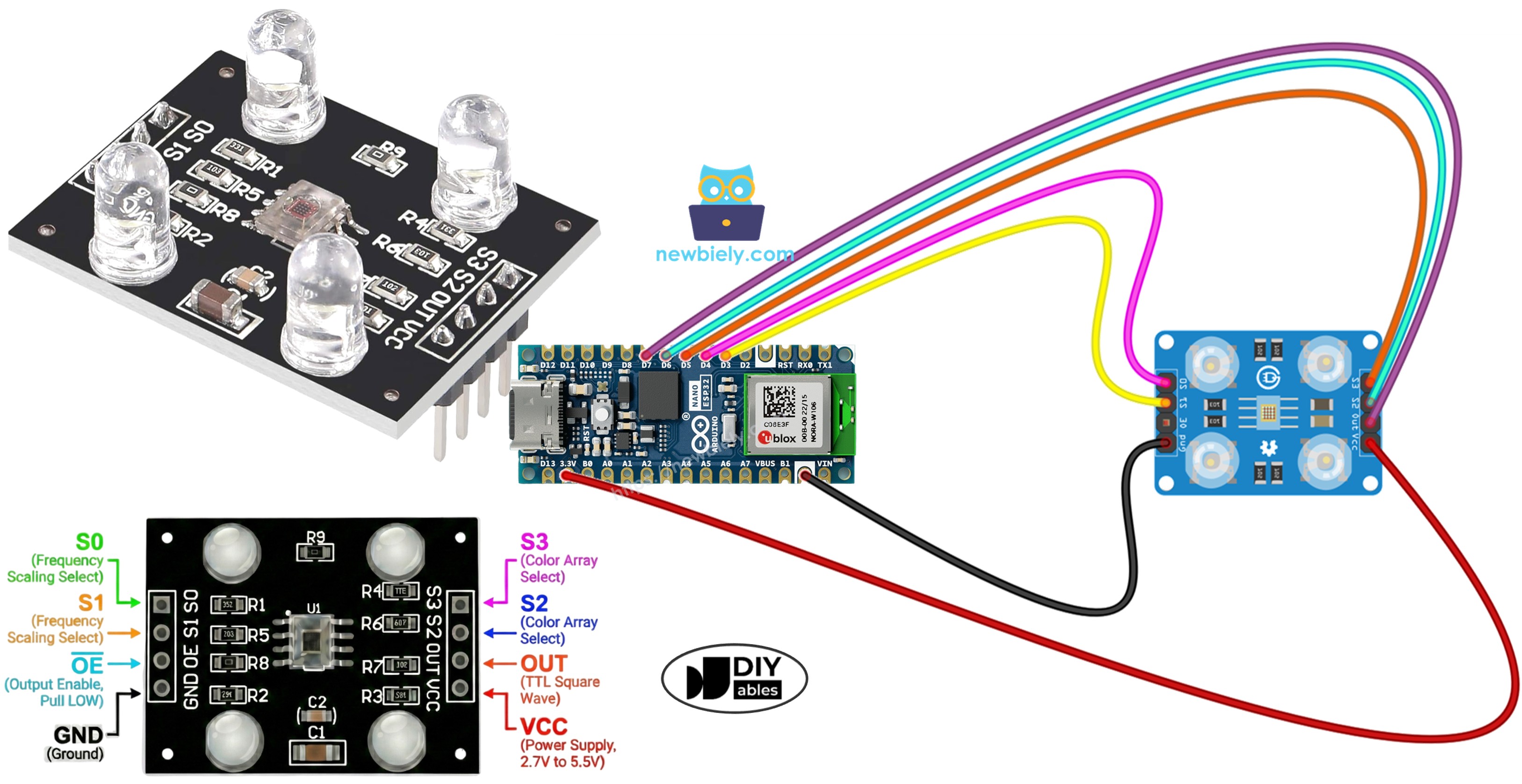
Wiring Diagram
Wire the TCS3200 color sensor to Arduino Nano ESP32 according to this configuration:
| TCS3200 Color Sensor | Arduino Nano ESP32 |
|---|---|
| VCC | 5V |
| GND | GND |
| S0 | D4 |
| S1 | D3 |
| S2 | D6 |
| S3 | D5 |
| OUT | D7 |
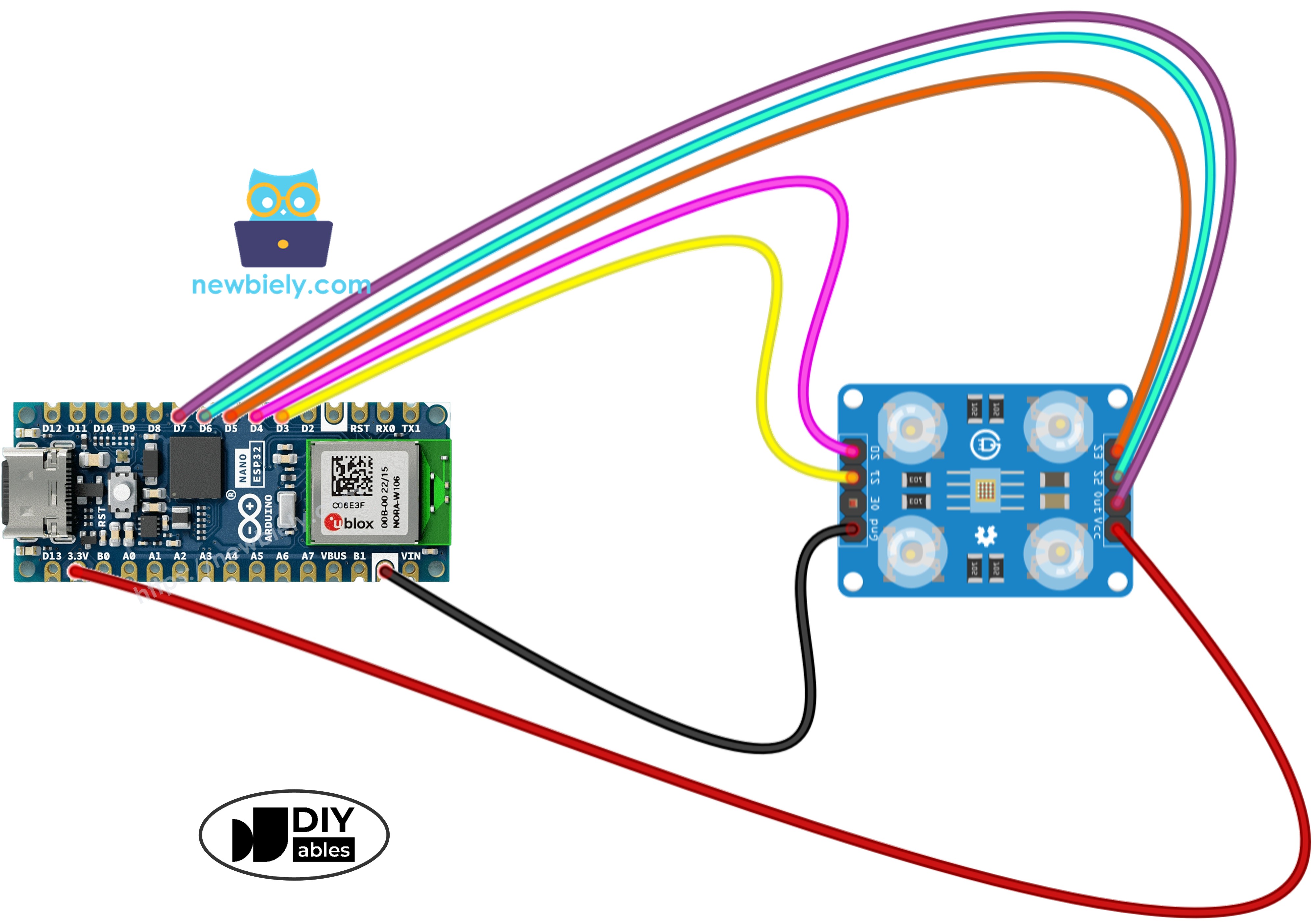
This image is created using Fritzing. Click to enlarge image
Arduino Nano ESP32 Code - Sensor Calibration
Calibration neutralizes environmental factors affecting sensor performance. Variables such as LED intensity, object proximity, surface characteristics, and surrounding illumination all impact raw measurements. This calibration workflow determines minimum and maximum pulse durations for each color channel, creating reference boundaries that translate raw sensor output into standardized 0–255 RGB values optimized for your deployment conditions.
Detailed Instructions
To get started with Arduino Nano ESP32, follow these steps:
- If you are new to Arduino Nano ESP32, refer to the tutorial on how to set up the environment for Arduino Nano ESP32 in the Arduino IDE.
- Wire the components according to the wiring diagram.
- Connect the Arduino Nano ESP32 board to your computer using a USB cable.
- Launch Arduino IDE on your computer.
- Select the Arduino Nano ESP32 board and its corresponding COM port.
- Copy the calibration code and paste it into Arduino IDE.
- Click the Upload button to compile and upload the code.
- Open the Serial Monitor to observe calibration progress.
- Direct the sensor toward different colored surfaces: white materials (paper), black surfaces, and various colored objects.
- Monitor the Min/Max parameters as they update in real-time.
- When values reach stability (usually 10-20 seconds), record all six calibration numbers.
Calibration parameters extracted from example output:
- RedMin = 42, redMax = 210
- GreenMin = 55, greenMax = 185
- BlueMin = 60, blueMax = 172
Arduino Nano ESP32 Code - RGB Color Reading
Detailed Instructions
- Find the calibration variable declarations near the beginning of the code:
- Insert your recorded calibration values in place of zeros. Example substitution with redMin = 42, redMax = 210, greenMin = 55, greenMax = 185, blueMin = 60, blueMax = 172:
- Upload the updated code to Arduino Nano ESP32.
- Place a colored target in front of the sensor.
- Open Serial Monitor to view RGB measurements.
Output RGB values adhere to standard 0-255 scaling. Shorter pulse widths (intense reflections) map to higher RGB numbers; longer pulse widths (weak reflections) map to lower values.
Project Applications
With functional RGB color sensing, you can build:
- Automated color sorter: Classify items based on chromatic properties (red/green/blue categorization)
- Color comparison tool: Verify color consistency across multiple samples
- Color-guided navigation: Robots that follow colored pathways
- Manufacturing inspection: Identify product defects through color deviation
- Color-activated control: Trigger specific behaviors when particular colors appear