
Arduino Nano 33 IoT - NTC Thermistor Temperature Sensor
This tutorial instructs you how to use Arduino Nano 33 IoT to read temperatures from a waterproof 10K NTC thermistor probe, the steel-tipped kind you can leave in a freezer, a fish tank or a seed tray. With the Wi-Fi on the board, this cheap probe is the first step toward a monitor that warns your phone when something gets too warm or too cold. In detail, we will learn:
- What sits inside the steel probe, and what each of its two wires and the 10K resistor must be connected to
- Why the probe takes its power from the 3.3V pin of the Arduino Nano 33 IoT, and never from VUSB
- How to program the Arduino Nano 33 IoT to average sixteen 12-bit readings and work out the resistance of the thermistor
- How to turn that resistance into °C and °F with the B (beta) equation, and print a hint when a wire comes loose
We suggest:
- Trying the Arduino Nano 33 IoT - Temperature Sensor tutorial when you want several waterproof probes on one data pin. Its DS18B20 probes each have their own address and report a finished digital value.
- Switching to the Arduino Nano 33 IoT - MAX6675 Thermocouple Module tutorial for anything hotter than 105°C, the limit of this probe, such as a wood stove or a soldering hot plate.
Hardware Preparation
Or you can buy the following kits:
| 1 | × | DIYables Sensor Kit (18 sensors/displays) |
Additionally, some of these links are for products from our own brand, DIYables .
Overview of NTC Thermistor Temperature Sensor and Its Pinout
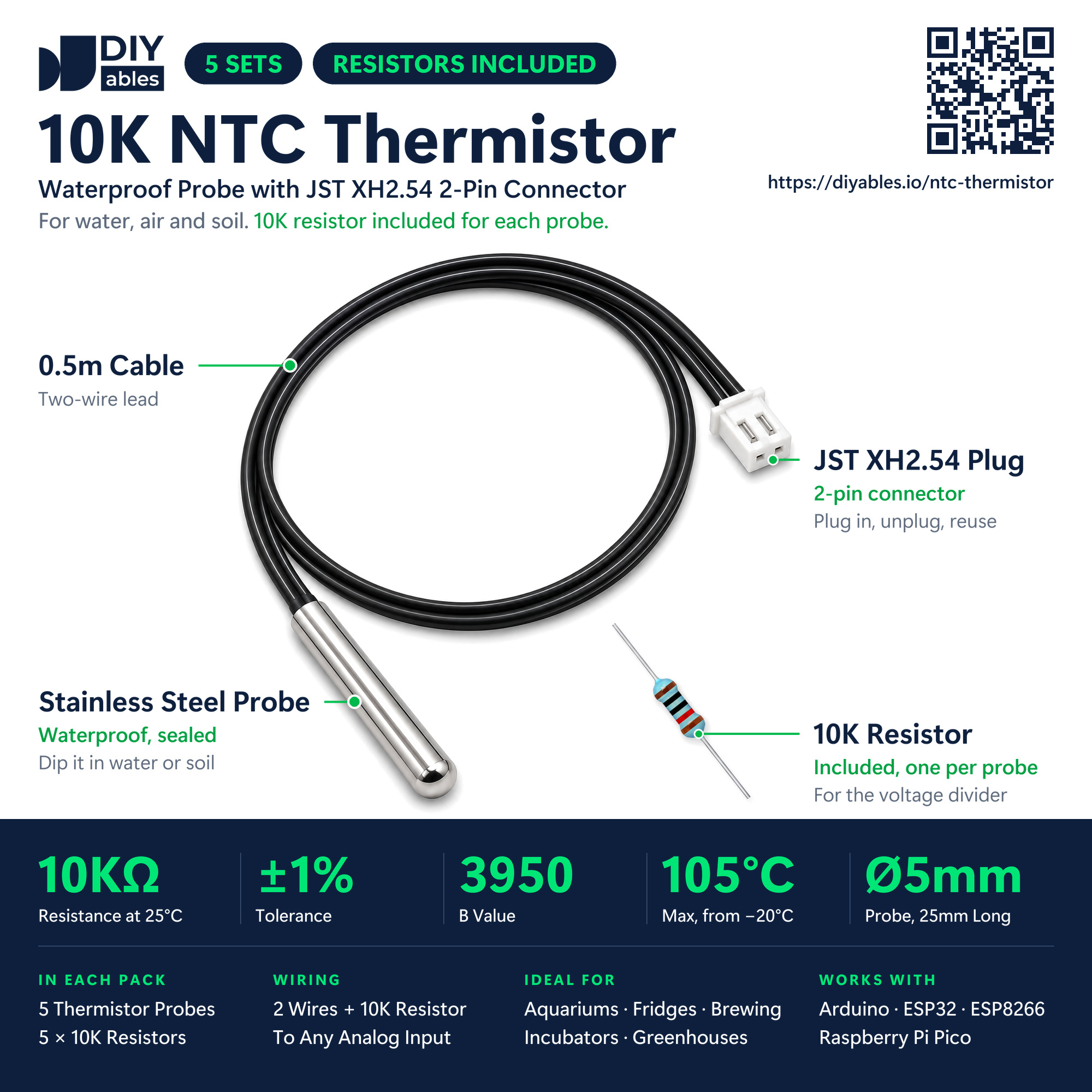
The probe looks like a short metal pen tip on a thin black cable. Its closed stainless-steel tube keeps water away from the one tiny part sealed inside: a 10K NTC thermistor. The 0.5m cable ends in a white JST XH2.54 plug with two sockets, and male jumper wires push straight into them. No soldering, no adapter board. DIYables sells the probe in a set of five, each with its own 10K resistor. Keep that resistor: the circuit below needs it.
| DIYables 10K NTC Thermistor Probe | |
|---|---|
| Thermistor type | NTC, B value 3950 |
| Resistance at 25°C | 10kΩ, ±1% |
| Temperature range | -20°C to 105°C |
| Tip | stainless steel, 5mm x 25mm, round end, waterproof |
| Lead | 0.5m cable with two black wires |
| Plug | white JST XH2.54, 2 pins |
| Insulation resistance | more than 100MΩ |
| In the box | one 10K resistor for each probe |
Two wires come out of the plug. They look the same, and neither one is marked:
- First wire (either one): must be connected to the 3.3V pin of the Arduino Nano 33 IoT (printed 3V3 on the board)
- Second wire: must be connected to analog pin A7
- 10K resistor from the kit: must be connected from A7 to a GND pin, so that A7 also has a path to 0V
※ NOTE THAT:
Swapping the two probe wires changes nothing. A thermistor works like any resistor, in both directions. Only the 10K resistor has a fixed spot, from A7 down to GND. Put it between 3.3V and A7 instead, and the reading falls as the probe warms up, so the formula in the sketch gives wrong numbers.
How Does the Probe Measure Temperature?
NTC stands for Negative Temperature Coefficient. Put simply: heat makes the resistance of the thermistor smaller. The Arduino Nano 33 IoT cannot measure ohms, only voltage, so the probe and the 10K resistor form a voltage divider between 3.3V and GND, with A7 in the middle. A warmer tip has less resistance, so a bigger share of the 3.3V shows up on A7. The sketch reads that voltage, works back to the resistance, and then to degrees. Here is what you can expect with this wiring:
| Probe temperature | Thermistor resistance | Voltage on A7 | Reading (0 to 4095) |
|---|---|---|---|
| -15°C | about 77.9kΩ | 0.38V | about 466 |
| 5°C | about 25.9kΩ | 0.92V | about 1140 |
| 20°C | about 12.5kΩ | 1.46V | about 1817 |
| 45°C | about 4.3kΩ | 2.30V | about 2854 |
| 90°C | about 0.93kΩ | 3.02V | about 3745 |
The Math Behind the Reading
These numbers do not follow a straight line, so the sketch uses the B-parameter (beta) equation:
1/T = 1/T0 + (1/B) × ln(R/R0)
T is the probe temperature in kelvin and R is the measured resistance. R0 = 10000Ω is the resistance at T0 = 298.15 K (25°C), and B = 3950. ln is the natural logarithm, called log() in Arduino code. T minus 273.15 gives °C. Lab instruments often use the three-constant Steinhart-Hart equation instead; for a hobby probe like this one, the single B value is plenty. Between 15°C and 35°C a reading normally stays inside ±1°C of the truth, and most of what is left comes from the 10K resistor and the 12-bit ADC.
Two tips before you build:
- The steel tip is waterproof, the white plug is not. Keep the plug and the resistor joint dry.
- The tip needs time to reach a new temperature: seconds in water, minutes in air. Trust a reading only when several lines in a row agree.
Wiring Diagram
Three connections make the whole circuit: one probe wire to 3.3V, the other to A7, and the 10K resistor from A7 to GND. We use A7 because it is only three pins away from GND, so the short resistor reaches both.
In the picture, the Arduino Nano 33 IoT sits across the middle gap of the breadboard, with its USB end to the left. So the row with 3V3, A0 to A7, VUSB, RST and GND is the lower row. The 10K resistor is plugged into row H. One leg is in the A7 column. The other leg is in the GND column, three columns to the right. The resistor jumps over the VUSB and RST columns and does not touch them. Two jumper wires go from row J to the white plug of the probe:
- Yellow wire: from the A7 column
- Red wire: from the 3V3 column at the far end, next to D13
Each hole takes a single wire or leg, and the resistor already touches GND, so there is no black wire in this build.
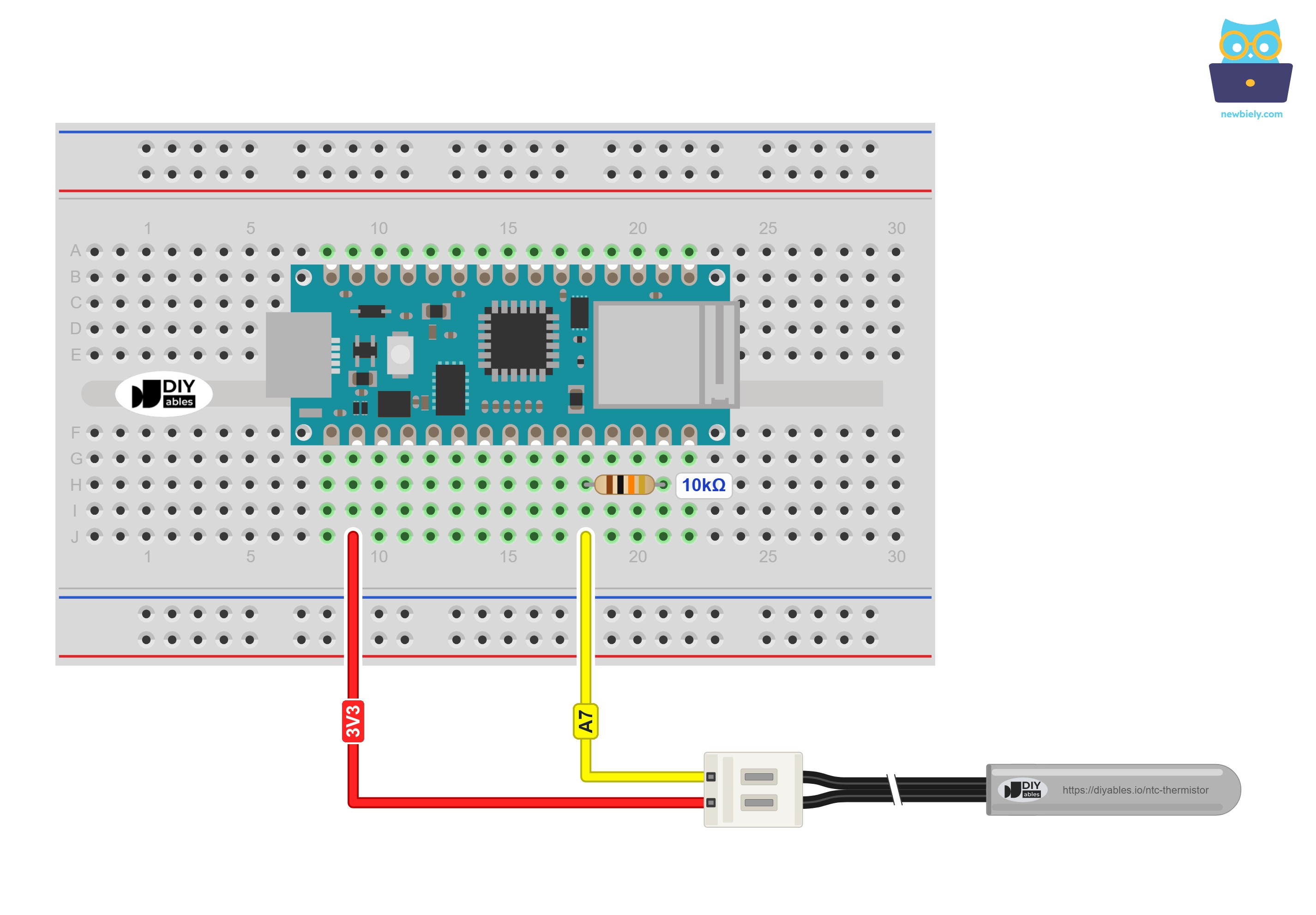
This image is created using Fritzing. Click to enlarge image
No breadboard? Then join the resistor legs to the A7 and GND wires, as shown here:
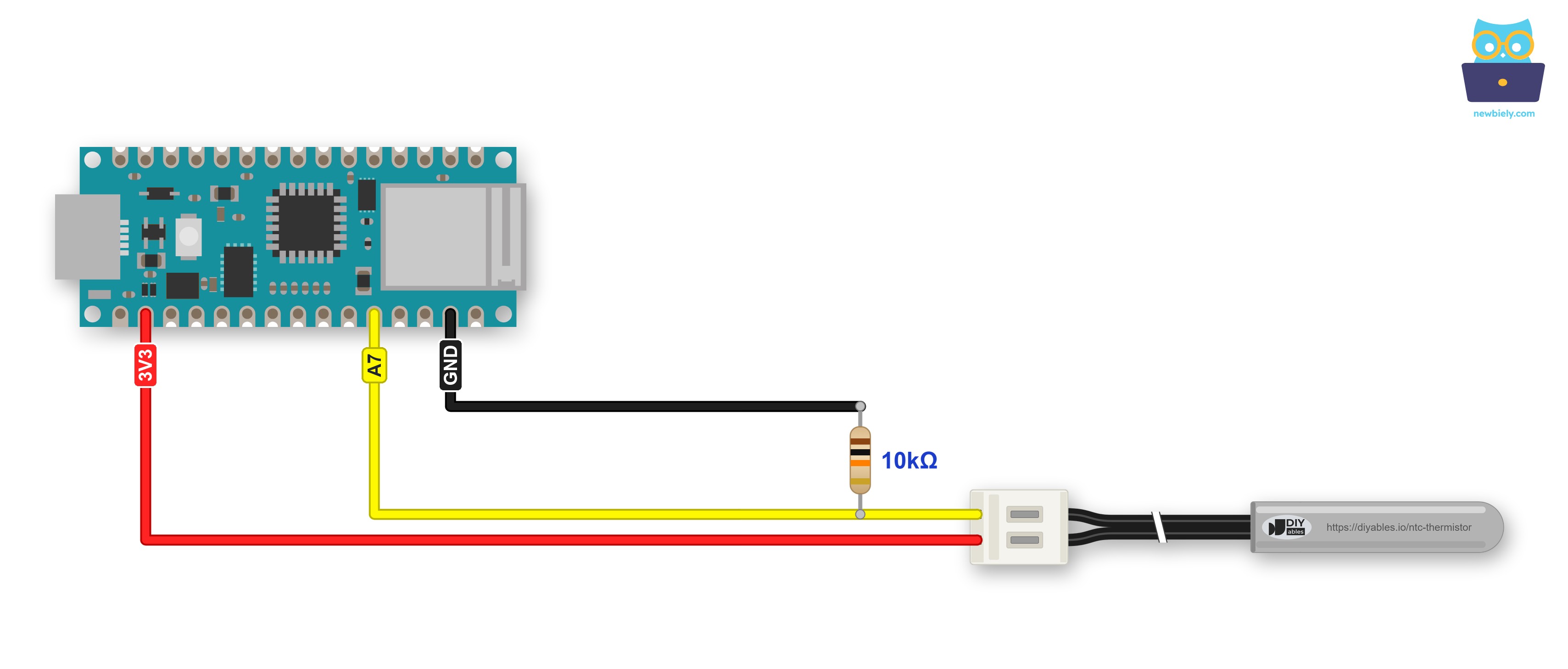
This image is created using Fritzing. Click to enlarge image
| NTC Thermistor Circuit | Arduino Nano 33 IoT Pin |
|---|---|
| One lead of the probe | 3.3V |
| Other lead of the probe | A7 |
| 10K resistor, first leg | A7 (shared with the probe lead) |
| 10K resistor, second leg | GND |
Want a stronger connection than jumper wires? To do that, mount the Arduino Nano 33 IoT on a Screw Terminal Expansion Board for Arduino Nano. The pins do not change. Just connect each wire to the matching screw terminal:
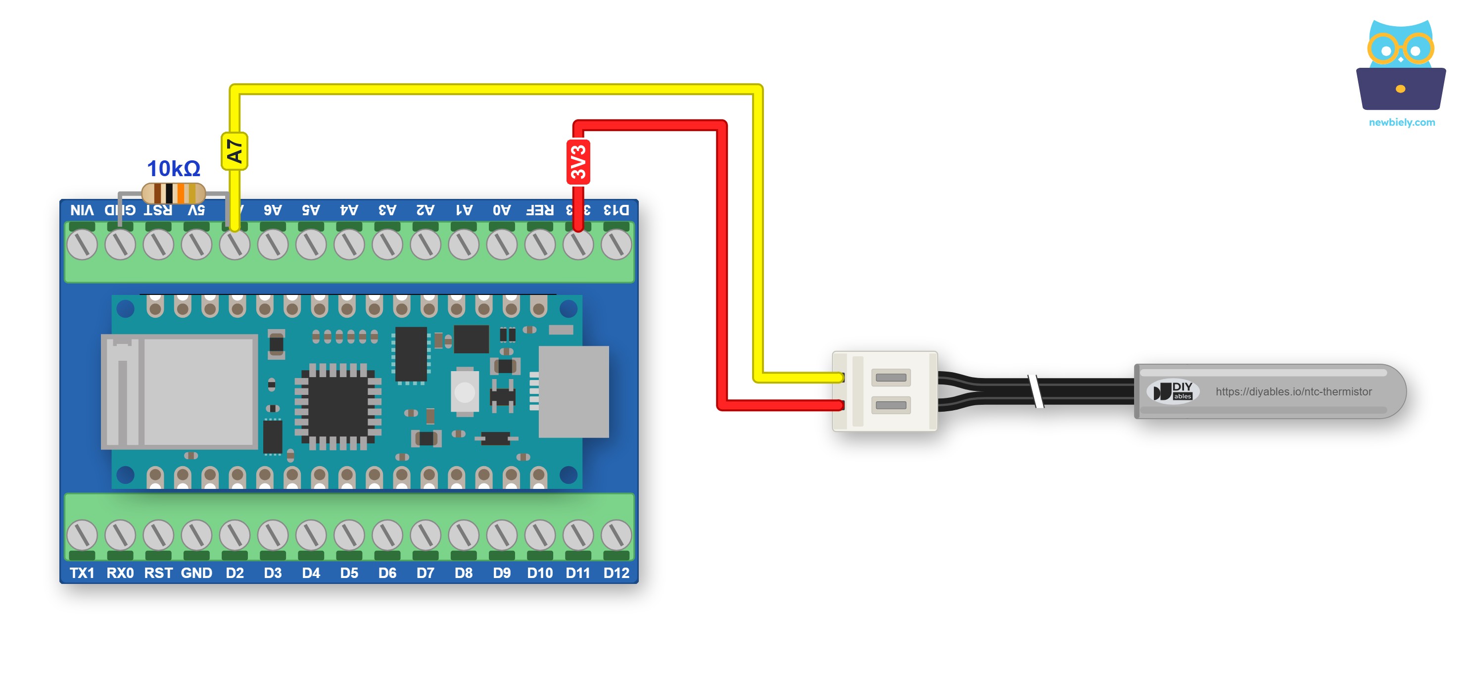
This image is created using Fritzing. Click to enlarge image
On the terminal block, the 10K resistor needs no wire of its own: one leg goes into the GND terminal, and the other shares the A7 terminal with the probe wire.
※ NOTE THAT:
Why 3.3V and not VUSB (5V)? The SAMD21 chip of the Arduino Nano 33 IoT measures A7 against 3.3V. When the divider runs from that same 3.3V, the sketch needs only the ratio between the reading and 4095, so small changes in the supply cancel out. With 5V on the probe, A7 would go above 3.3V once the tip is warmer than about 40°C, and the pins of this board are not 5V tolerant.
How To Program For NTC Thermistor
No library is needed. The math is a few lines of code, and log() is already part of Arduino.
- The first step is to name the Arduino Nano 33 IoT pin in the middle of the divider, then write down the values of the resistor and the probe:
- In setup(), switch the ADC from its default 10-bit to 12-bit. Then analogRead() returns 0 to 4095, and each step is about four times finer:
- Read A7 sixteen times with analogRead() and keep the average, adc_avg. This calms the small jumps between single readings.
- Work out the resistance of the probe. Both the divider and the ADC use 3.3V, so the voltage itself is not needed:
- Put the resistance into the B equation, then change kelvin to °C and °F:
Arduino Nano 33 IoT Code for NTC Thermistor Temperature Sensor
The full sketch runs these steps about once per second. Every line starts with the seconds since power-up (t) and the averaged reading (raw), followed by the resistance (R) and the temperature (T). Before the math, it checks the average. Close to 0 means no probe, because the 10K resistor then holds A7 at GND. Close to 4095 means the resistor is missing or the probe wires touch. In both cases the sketch prints a short hint instead of a strange temperature. Since the board uses its native USB port for Serial, setup() also waits up to 3 seconds for the Serial Monitor.
Detailed Instructions
Have you not set up the Arduino Nano 33 IoT in the Arduino IDE yet? Then follow the Getting Started with Arduino Nano 33 IoT tutorial first.
- Wire the components as shown in the diagram. Make sure the probe wire is on 3.3V, not on VUSB.
- Connect the Arduino Nano 33 IoT board to your computer using a USB cable.
- Open Arduino IDE on your computer.
- Choose the Arduino Nano 33 IoT board and its COM port.
- Paste the code above into a new sketch.
- Click the Upload button and wait until the upload is done.
- Open the Serial Monitor and set it to 9600 baud.
- Let the probe lie on the table for a few lines. Then lay the steel tip on a freezer shelf and lead the thin cable out through the door seal, so the door still closes. The board, the plug and the resistor stay outside.
The first three lines are room air; after that, only a few lines are shown to keep the list short. The probe went into the freezer at about 10 seconds. Cold air takes heat away much more slowly than water, so the tip needs about four minutes to reach the freezer temperature. Want a faster sanity check? Crushed ice topped up with a little water stays at 0°C, so dip the tip in that mix for a minute and the reading should end up close to zero.
A line ending in "no probe found" usually means one jumper wire has come out of the white plug. A line ending in "A7 is almost at 3.3V" points to the 10K resistor: check that it still links A7 to GND.
Additional Knowledge
Probe on the 3.3V Side or on the GND Side?
In this tutorial the probe sits between 3.3V and A7, and the 10K resistor between A7 and GND. Many thermistor examples on the internet do it the other way round. Both work, but each one needs its own formula:
| Probe on the 3.3V side (this tutorial) | Probe on the GND side | |
|---|---|---|
| Where the 10K resistor goes | between A7 and GND | between 3.3V and A7 |
| When the tip gets warmer | the reading goes up | the reading goes down |
| Resistance of the probe | R = 10000 × (4095 / reading - 1) | R = 10000 × reading / (4095 - reading) |
| Probe unplugged | reading near 0 | reading near 4095 |
| Probe wires shorted | reading near 4095 | reading near 0 |
It is evident that both ways measure the temperature equally well. What counts is that the wiring, the resistance formula and the error checks in the sketch all match. If you copy code from another project, check which side its probe is on first. This tutorial keeps the probe on the 3.3V side, so a warmer tip gives a bigger number, which is easy to follow.
Project Ideas
The Wi-Fi of the Arduino Nano 33 IoT turns this probe into more than a desk thermometer:
- A pipe-freeze warning for a garden shed or a holiday house: a message on your phone when the water pipe gets close to 0°C
- A seed-tray or greenhouse logger that sends the soil temperature to a cloud dashboard
- An aquarium thermometer on a web page. The Arduino Nano 33 IoT - Temperature via Web tutorial already does this with a DS18B20; swap in the reading code from this page
- An egg incubator helper that turns a heater on and off with a relay to stay close to 37.5°C