
ESP32 S3 UNO - NTC Thermistor Temperature Sensor
A glass thermometer makes you wait, tilt your head and guess where the thin red line stops. A thermistor probe does the same job without the guessing. Its steel tip goes into water, soil or air, and the ESP32 S3 Uno reads the temperature from it once per second, as a number you can print, log or later send over WiFi.
The plan for this page:
- Meet the waterproof steel probe, its white 2-pin plug and the 10K resistor that comes with it
- Build a small voltage divider on the 3.3V, A0 (GPIO2) and GND pins
- Turn calibrated millivolts into ohms, and ohms into °C and °F
- Test it with a mug of hot water and watch the numbers climb
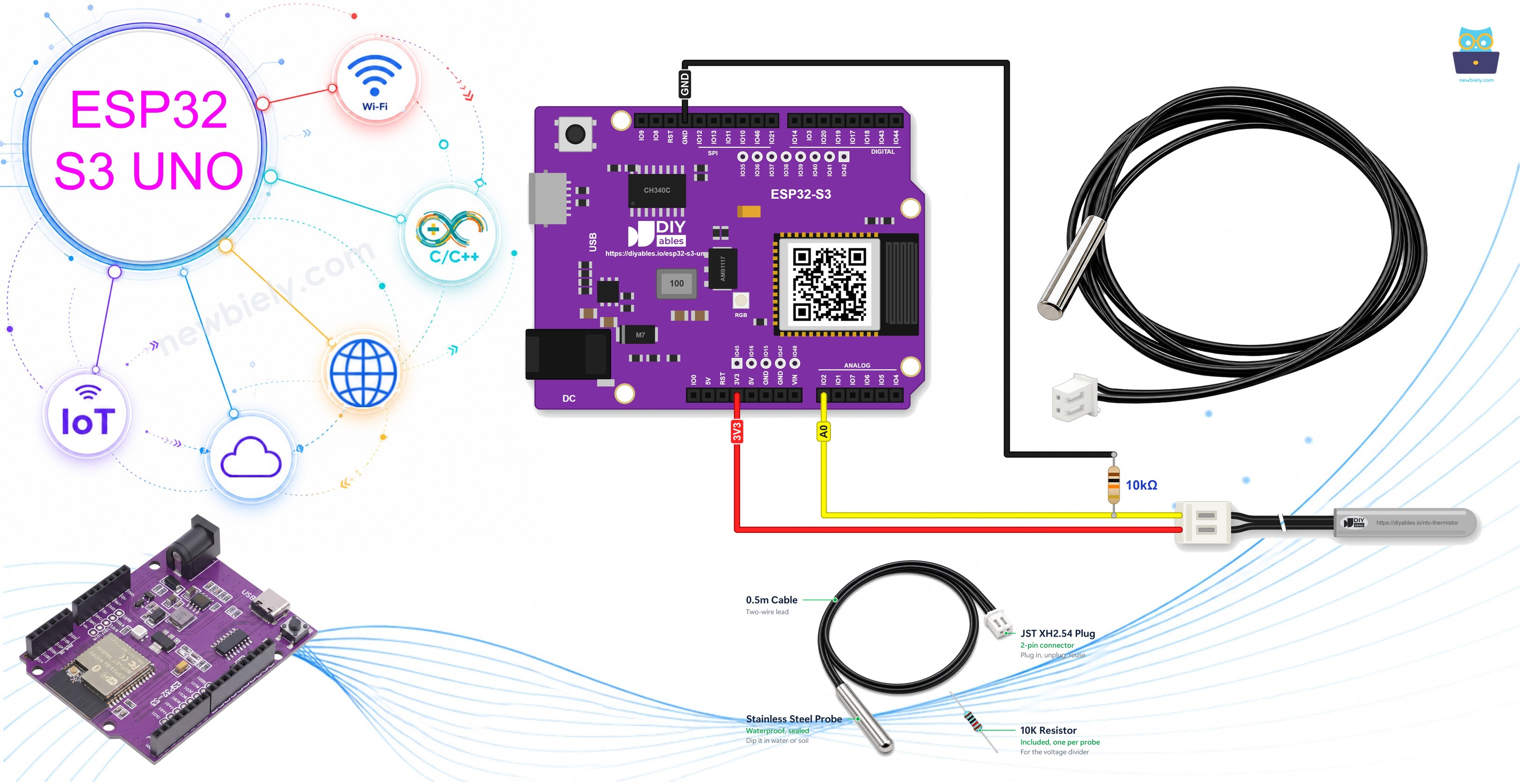
There is no library to install. The sketch needs only a few lines of math, and the log() function it uses is already built into Arduino.
Hardware Preparation
Or you can buy the following kits:
| 1 | × | DIYables Sensor Kit (18 sensors/displays) |
Additionally, some of these links are for products from our own brand, DIYables .
Overview of NTC Thermistor Temperature Sensor
The DIYables kit holds five sets. Each set is one probe plus one matching 10K resistor, so you never have to hunt for the right resistor. The probe is a small stainless-steel tube, 5mm wide and 25mm long, with a round, sealed tip. A 0.5m black cable runs from the tube to a white JST XH2.54 plug with two holes.
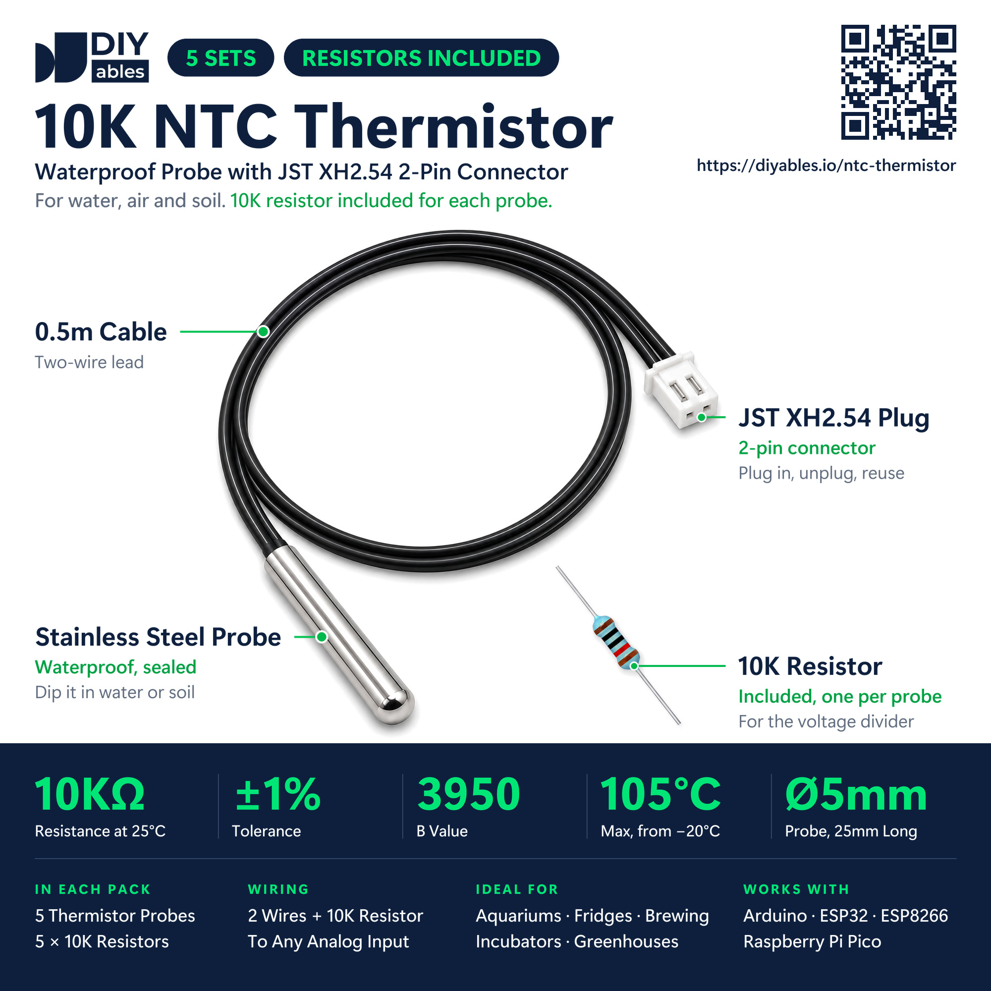
The thermistor sits inside the steel tip. It is a resistor and nothing else: no chip, no small board, no third wire. That makes the two wires the same. Push a male jumper wire into each hole of the plug, then:
- Either wire: goes to the 3.3V pin.
- The other wire: goes to A0 (GPIO2), together with one leg of the 10K resistor.
- The free leg of the 10K resistor: goes to GND.
| DIYables 10K NTC Thermistor Probe | |
|---|---|
| Thermistor | NTC, 10kΩ at 25°C, ±1% |
| B value (beta) | 3950 |
| Measuring range | -20°C to 105°C |
| Probe | stainless steel, waterproof, 5mm x 25mm, round tip |
| Cable | 0.5m, black, 2 wires |
| Plug | white JST XH2.54, 2 pins, no polarity |
| Output | a resistance, read through a 10K voltage divider |
| In the pack | 5 probes and 5 matching 10K resistors |
From heat to a number
NTC stands for Negative Temperature Coefficient. In plain words: when the tip gets warmer, its resistance goes down, and when it gets colder, its resistance goes up. The ESP32 S3 Uno can measure a voltage, but not ohms. So the thermistor and the 10K resistor share the 3.3V, and the board reads the voltage where they meet. The code turns that voltage into ohms, and the ohms into degrees.
| Probe temperature | Thermistor resistance | Voltage on A0 |
|---|---|---|
| -10°C | about 58.2kΩ | 0.48V |
| 5°C | about 25.9kΩ | 0.92V |
| 25°C | 10.0kΩ | 1.65V |
| 60°C | about 2.5kΩ | 2.64V |
| 95°C | about 0.8kΩ | 3.05V |
A warmer probe gives a higher voltage. At 25°C the two parts are equal, so A0 sits right in the middle, at 1.65V.
The code uses the B-parameter equation (also called the beta formula) to go from ohms to degrees:
1/T = 1/T0 + (1/B) × ln(R / R0)
Here T is the probe temperature in kelvin, T0 = 298.15K (25°C), R0 = 10000Ω, B = 3950, and R is the resistance the board just measured. Take 273.15 away from T and you have °C. Datasheets sometimes show the Steinhart-Hart equation instead; it fits the curve with three constants rather than one, which helps over very wide ranges. Across this probe's -20°C to 105°C span, the single B value works fine. Around room temperature the result usually lands within about 1°C of a good thermometer, and the tolerance of the 10K resistor plus the board's ADC set the rest of the error.
ESP32 S3 Uno Pinout
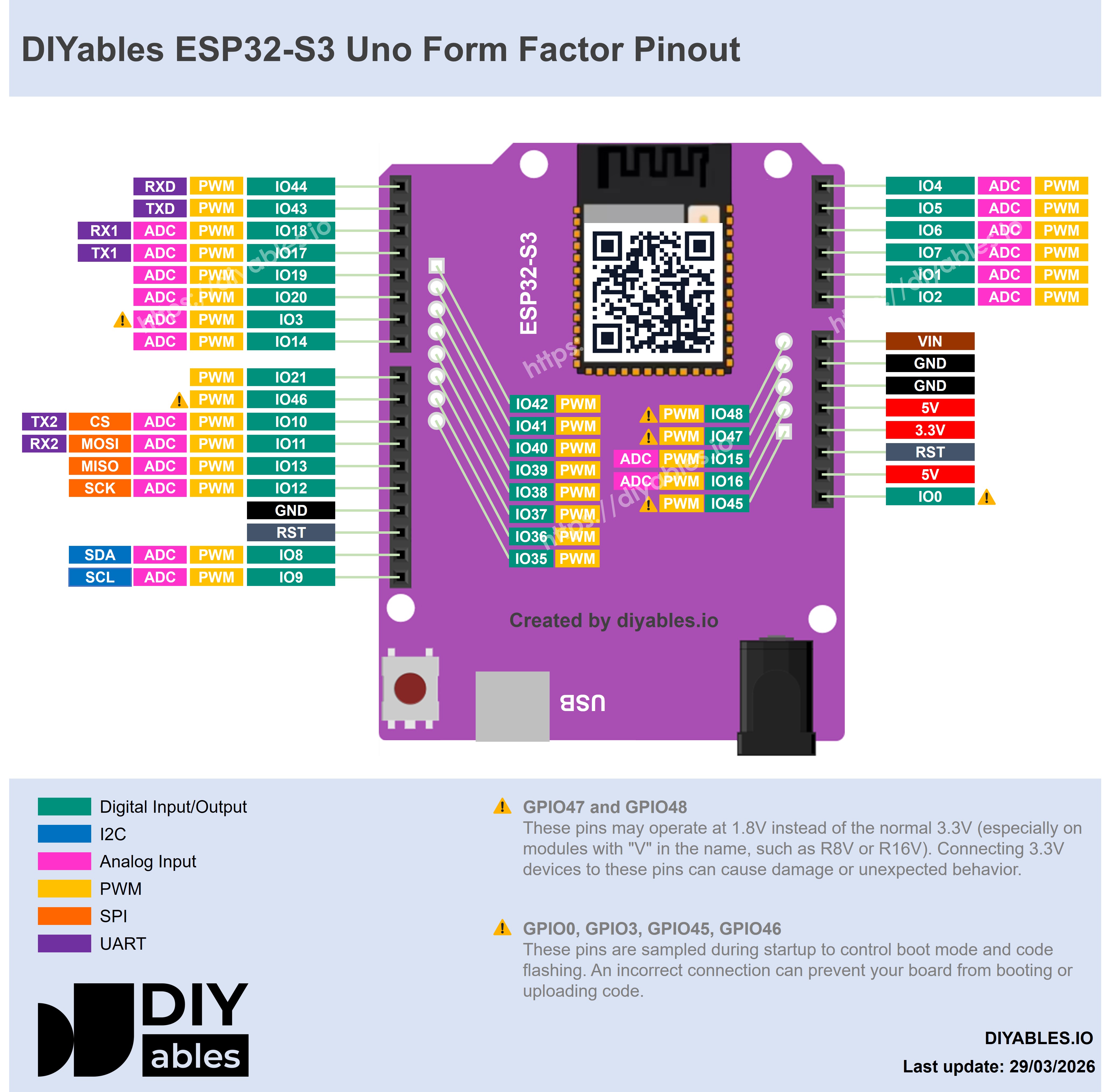
Below is the pinout of the ESP32 S3 Uno form board. Three header spots matter for this project: 3.3V and GND on the power header, and A0 on the analog header. Inside the ESP32-S3 chip, A0 is GPIO2. It belongs to ADC1, the converter that WiFi does not borrow, so a web thermometer can come later without moving the wire.
Wiring Diagram
The whole circuit is the probe, the 10K resistor and three jumper wires. The one spot to watch is A0, where a probe wire and a resistor leg must meet. In the drawing, the resistor hangs between the A0 wire and the GND wire. A small breadboard makes that junction easy. With no breadboard, twist the resistor leg tightly around the jumper wire pin, or solder it.
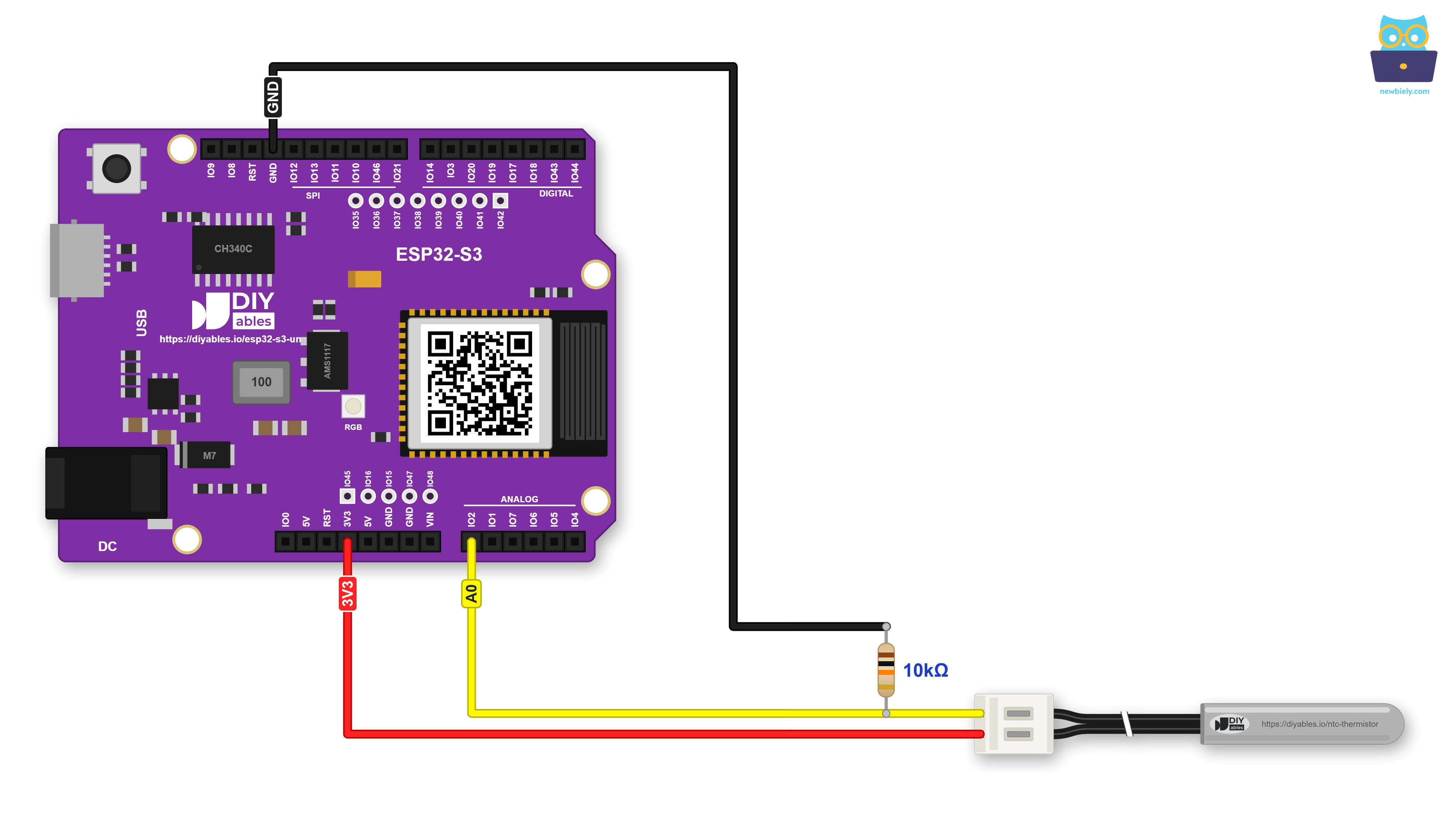
This image is created using Fritzing. Click to enlarge image
| NTC Thermistor Circuit | ESP32 S3 Uno Pin |
|---|---|
| Probe wire (either one) | 3.3V |
| Other probe wire | A0 (GPIO2) |
| 10K resistor, leg 1 | A0 (GPIO2) |
| 10K resistor, leg 2 | GND |
If you plan to keep this circuit, think about screw terminals. Put a Screw Shield V2 or a Proto Screw Terminal Block Shield on top of the ESP32 S3 Uno, then tighten each wire under a screw. This is how it looks with the Screw Shield V2:
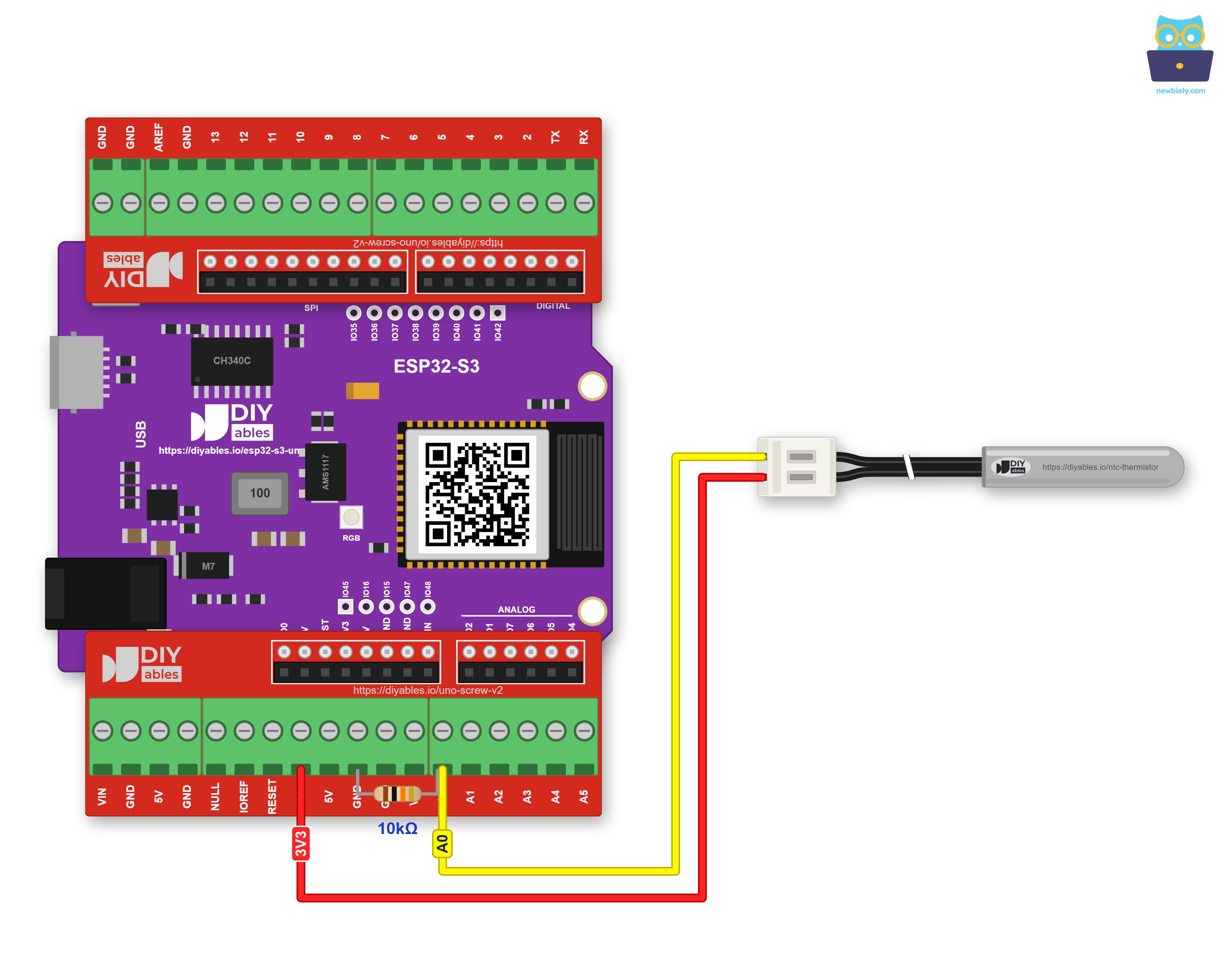
This image is created using Fritzing. Click to enlarge image
Notice that the resistor is screwed in as well. Its legs go into a GND terminal and into the A0 terminal, where they share the hole with the probe wire, so there is no separate GND wire.
WARNING
Feed the probe from the 3.3V pin, never from 5V. A hot probe has a low resistance, so the voltage on A0 climbs close to the supply voltage. With a 5V supply, A0 would pass 3.3V as soon as the probe is warmer than about 41°C, which is just a cup of hot tea. The ESP32 S3 Uno pins are not 5V tolerant, so this can damage GPIO2.
The sketch counts on 3.3V too: it uses 3300 mV as the top of the divider. If a multimeter shows a slightly different voltage on your 3.3V pin, for example 3.28V, write that value into SUPPLY_MV in the code (3280.0) for a closer reading.
※ NOTE THAT:
The steel tip and the cable are made for water. The white plug, the jumper wires and the resistor are not. Put only the probe and a part of the cable into the liquid, and keep the A0 junction dry.
ESP32 S3 Uno Code - NTC Thermistor Temperature Sensor
Every second, the sketch takes ten millivolt readings on A0 (GPIO2) and averages them. It turns the average into the thermistor's resistance, then into °C and °F, and prints all four values on one line.
Detailed Instructions
- First project on this board? Set up the ESP32 core in Arduino IDE with ESP32 S3 Uno - Getting Started.
- Build the circuit from the table above. Push two jumper wires into the white plug of the probe.
- Connect the board to your computer with a USB Type-C cable.
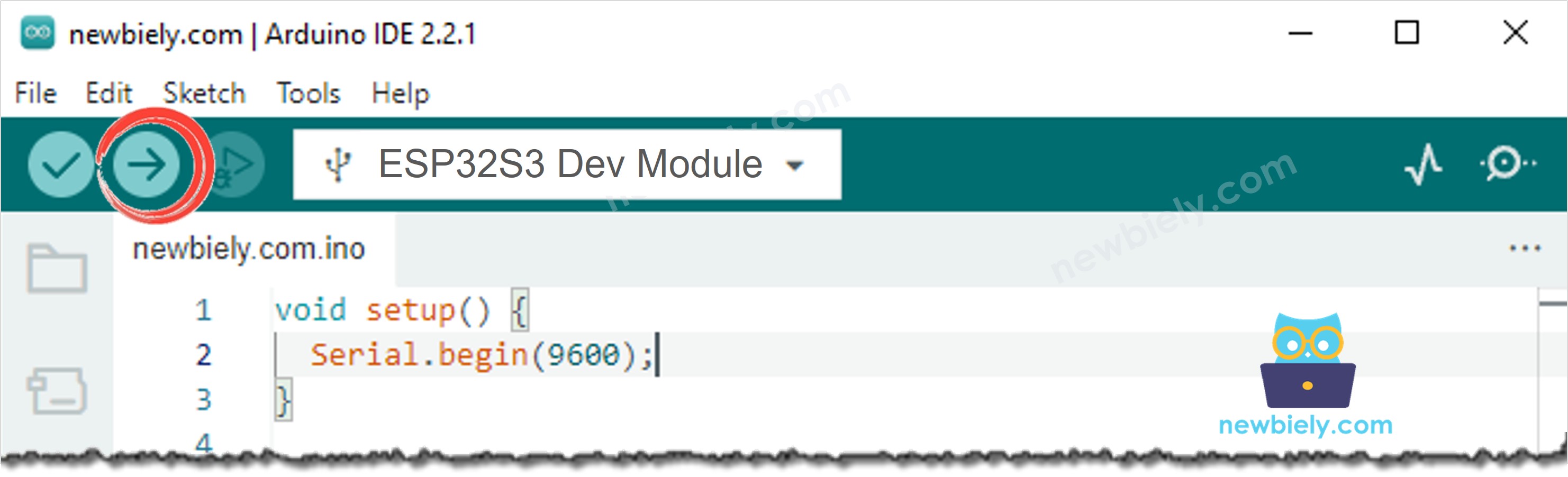
- Choose ESP32S3 Dev Module and its COM port in Arduino IDE.
- Copy the code into a new sketch and click Upload.
- Open the Serial Monitor at 9600 baud and leave the probe untouched on the table until a few readings scroll by.
- Dip the steel tip into a mug of hot water. Water from a kettle that has cooled for a few minutes is fine. Hold the cable, not the plug. After a while, lift the probe out again:
- Look at how the numbers move. The jump from the desk to the water takes about six lines, because the steel tube needs a few seconds to take on the new temperature. Wait until the value stops changing before you trust it.
How the Sketch Works
- The pin is a GPIO number. On the ESP32 S3 Uno, the A0 header is GPIO2, so the code writes 2:
Do not write A0 here. With the ESP32S3 Dev Module setting, A0 means GPIO1, and that is the A1 header.
- The widest input range. analogSetAttenuation(ADC_11db) in setup() lets A0 measure from 0V up to about 3.1V, so even a hot probe (about 3.05V at 95°C) still fits.
- Ten readings, one average. A single thermistor reading jumps a little, so the loop adds up ten of them:
analogReadMilliVolts() uses calibration data that was stored in the chip at the factory. The FAQ below tells why the raw count is not used.
- Millivolts to ohms.
The same current flows through the thermistor and the 10K resistor. The resistor holds pin_mv, and the thermistor holds the rest, 3300 - pin_mv. Their resistances have the same ratio as their voltages. Example: 1650 mV on A0 means both halves are equal, so the probe is 10000Ω, and that is 25°C.
- Ohms to degrees. Two lines follow the B formula from above. One more line makes °F:
In Arduino code, log() is the natural logarithm, the "ln" of the formula.
- A wiring check comes first. Below 100 mV, the probe is missing and the 10K resistor holds A0 at GND. At 3100 mV or more, A0 is at the top of the scale: a shorted probe or a wrong wire. The math would give nonsense in both cases, so the sketch prints a hint instead.
Video Tutorial
Additional Knowledge
Thermistor, DS18B20 or thermocouple?
The ESP32 S3 Uno folder has a tutorial for each of these three temperature sensors. They suit different jobs:
| NTC thermistor (this page) | DS18B20 waterproof probe | MAX6675 + Type-K thermocouple | |
|---|---|---|---|
| Signal to the board | analog voltage, with a 10K resistor | digital, 1-Wire | digital, SPI-style |
| Temperature range | -20°C to 105°C | -55°C to 125°C | 0°C to 1024°C (module) |
| Library | none | OneWire + DallasTemperature | MAX6675 |
| Best for | a cheap probe and simple code | several probes on one data pin | ovens, grills and kilns |
Read ESP32 S3 Uno - Temperature Sensor for the DS18B20, with no resistor math at all. For anything above 105°C, such as an oven, go to ESP32 S3 Uno - MAX6675 Thermocouple Module.
Ideas for the thermistor probe
- Fridge alarm: sound a piezo buzzer once the fridge has been warmer than 8°C for ten minutes in a row.
- Fish tank display: show the water temperature on an LCD I2C screen next to the tank.
- Seed tray warmer: switch a heating pad on and off with the code from ESP32 S3 Uno - Controls Heating Element.
- Thermometer in the browser: join this sketch with ESP32 S3 Uno - Web Server and read the temperature on your phone.
Function References
FAQ
Which probe wire goes to 3.3V?
Either one. A thermistor is a plain resistor, so it has no plus and no minus. Swap the two wires in the plug and the readings stay the same. Only the place of the 10K resistor matters: it must sit between A0 and GND.
Why does the code not use analogRead() and 4095?
On the ESP32-S3, the full scale with 11 dB is about 3.1V, not 3.3V, and the raw count bends near 0V and near the top. A small voltage error turns into a temperature error. analogReadMilliVolts() corrects this with the factory calibration in the chip and gives the voltage directly, so the code can use 3300 mV as the top of the divider.
Why is the reading less exact near 100°C?
At 95°C, A0 is already at about 3.05V, close to the 3.1V top of the ESP32-S3 ADC. Up there, a small voltage step means a big temperature step, and the ADC is least straight at that end. Treat readings of boiling water as a rough guide. Above about 103°C, the sketch prints the "near 3.3V" hint instead of a temperature.
Can I read all five probes from the kit?
Yes. Give each probe its own analog pin and its own 10K resistor. A1 (GPIO1), A2 (GPIO7), A3 (GPIO6), A4 (GPIO5) and A5 (GPIO4) are ADC1 pins like A0, so they keep working with WiFi on. Copy the reading code once per pin. Avoid the ADC2 pins (for example GPIO15 and GPIO16 on the extra rows) if you plan to use WiFi.
Troubleshooting
| Problem | Possible Cause | Solution |
|---|---|---|
| Message "A0 is near 0V" | The probe is not powered or the plug is loose | Push both jumper wires fully into the white plug and check the wire to 3.3V |
| Message "A0 is near 3.3V" | The 10K resistor does not reach GND, or the probe is shorted | Check that the second leg of the resistor sits on GND, then check the probe cable for damage |
| Temperature drops when the probe gets warm | Probe and resistor swapped | Put the probe between 3.3V and A0, and the resistor between A0 and GND |
| Room reading is several degrees off | A resistor from another kit, or a different probe type | Use the 10K resistor from the kit. A multimeter should show about 10kΩ across it |
| Value moves while the water is still | Loose junction on the breadboard | Press the resistor legs and the jumper wires firmly into the breadboard, or raise SAMPLE_COUNT |
| Readings stop after you add WiFi code | The probe moved to an ADC2 pin | Keep it on A0 (GPIO2) or another ADC1 pin |
| No COM port in Arduino IDE | USB driver missing or charge-only cable | Install the CP210x or CH340 driver, use a data USB cable, or hold BOOT while you press RESET |
| Strange characters in the Serial Monitor | Baud rate does not match | Set the Serial Monitor to 9600 baud |